
SLRBT10 - Radio SereneLife - Free user manual and instructions
Find the device manual for free SLRBT10 SereneLife in PDF.

| Product Type | 2.4G Wireless RC Boat |
| Brand | SereneLife |
| Model | SLRBT10 |
| Boat Dimensions | 342 x 89 x 88 mm |
| Maximum Speed | Up to 25 km/h |
| Motor Type | 370 Magnetic Motor |
| Frequency | 2.4 GHz |
| Control Range | Up to 120 m |
| Boat Battery | Rechargeable Li-ion |
| Charging Time | Approx. 90 minutes |
| Transmitter Battery | 4 x 1.5V AA (not included) |
| Anti-Capsize Function | Yes |
| Motor Cooling System | Yes |
| Navigation Rudder | Built-in left and right |
| Low Battery Alarm | Yes (transmitter sounds dididi) |
| Poor Signal Alarm | Yes (transmitter sounds di.di.di.di-di.di.di.di.di) |
| Suitable Age | 14+ under adult supervision |
| Cleaning Method | Dry soft cloth |
| Long-Term Storage | Remove boat battery |
| Spare Parts Available | Yes (steering engine, propeller, tail rudder, etc.) |
| Country of Origin | China |
Frequently Asked Questions - SLRBT10 SereneLife
User questions about SLRBT10 SereneLife
0 question about this device. Answer the ones you know or ask your own.
Ask a new question about this device
Download the instructions for your Radio in PDF format for free! Find your manual SLRBT10 - SereneLife and take your electronic device back in hand. On this page are published all the documents necessary for the use of your device. SLRBT10 by SereneLife.
USER MANUAL SLRBT10 SereneLife
natural_image
Line drawing of a futuristic jet engine with mounting bracket (no text or symbols)


Operation Manual for 2.4 G Wireless RC Boat
- The product adopts 370 magnetic motor driving system as well as advanced 2.4 G frequency pairing automatically technology for longer controlling distance.
- Be equipped with Li Battery. The highest speed is about 25km/h.
- Boat Specification: 342*89*88mm
- Special anti- capsize function: turn over when capsize for normal sailing.
- Motor cooling system: extend use life of the boat.
- Build-in left and right navigation rudder: enhance sailing stability.
- Low battery alarm function: the transmitter issues sound of "dididi..." low battery alarm. Please recall the boat in on minute.
- Poor Signal alarm function: the transmitter will issue alarm sound of di.di.di.di-di.di.di.di.di once the 2.4G signal becomes poor.
Security Warning
For the safety and avoid hitting people which around propeller, the boat can's work properly till put into the water. Never touch the rotating propeller.
- The product is suitable for more than 14 years old people. Please use it under adult's supervision and guidance.
- Never mixed use old and new battery or different types of batteries. Never charge a non-rechargeable battery.
- Never charge the battery at once after using till cooling down.
- Make sure that there is no one swimming around to avoid injury before sailing. Keep away form water plant and debris to avoid the propeller tied up in the water and cause damage.
- The effective control distance is about 120m. Never exceed the range or the boat may be out of control.
- The transmitter will issue sound of "dididi" when low battery in the sailing. At this time the boat will slow down and the battery only can maintain one minute. Please recall the boat in one minute to avoid out of control.
- When the boat sailing far away from the transmitter, the transmitter will issue alarm sound of di.di.di.di -di.di.di.di. Long distance between the boat and the transmitter will arouse poor signal, which will effect the timeliness and accuracy of the transmitter's low voltage alarm function. At this time, please control the boat sailing close to the transmitter (the transmitter power indicator light turns solid) to ensure the low voltage alarm function works well.
- Please power off the transmitter and the boat when the boat not in use.
- Please attach great importance on safety first when sailing. If the boat out of control, retrieve the boat by safe and reliable method. Never retrieve the boat without any safe measure.
Maintenance and Repair
- Take out the battery when the boat stops working.
- The RC boat surface should avoid long time exposure in case of paint-shedding. Each time after use, clean the boat surface by dry and soft cloth to absorb water. Keep the boat clean and dry.
- If the RC boat is not used for a long time, remove the battery to avoid leakage damaging form battery to the transmitter.
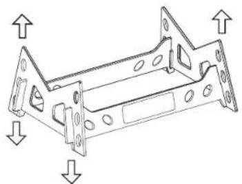
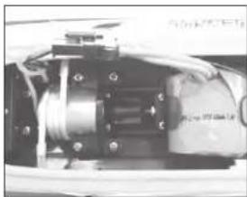
Picture for RC Boat Main Structure

natural_image
Technical line drawing of a metal bracket with mounting holes and directional arrows indicating force or movement (no text or symbols)Display Support Holder

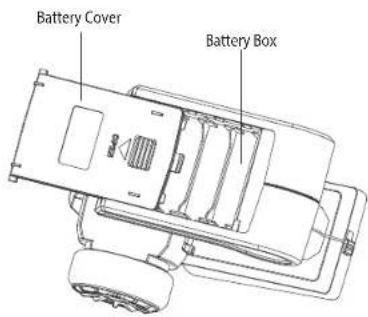
Transmitter Battery Installation
Battery installation: Open the battery cover of the transmitter. Install four 1.5V AA batteries to battery box in accordance with the positive and negative pole indication, and then close the battery box.
Battery Charging
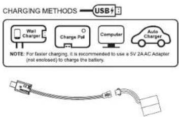
flowchart
graph TD
    A["USB+"] --> B["Charging Methods"]
    B --> C["Wall Charger"]
    B --> D["Charge Pad"]
    B --> E["Computer"]
    B --> F["Auto Charger"]
    C --> G["NOTE: For faster charging, it is recommended to use a 5V 2A-AC Adapter (not enclosed) to charge the battery."]
    D --> G
    E --> G
    F --> G
Connect the battery with USB wire, and then connect the USB with the computer or the adapter. The USB light is red when charging and turns to green when fully charged. The charging time is about 90 minutes. Please cut off the charging wire after fully charged.

ISIT US ONLINE:
Have a question?
Need service or repair?
Want to leave a comment?
PyleUSA.com/ContactUs

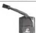
RC Boat Battery Installation
natural_image
Black-and-white photo of a vehicle with two arrows indicating speed or direction, no visible text or symbols- Twist the cabin cover switch to left or right, and then forced upward to lift the cabin cover.

natural_image
Close-up of a mechanical component with bolts and wiring (no visible text or symbols)- Put the Li battery to the battery box of the hull.
natural_image
Close-up of a mechanical assembly with no visible text or symbols- Connect the battery with the power plug.

- (1) Insert the cabin cover to the hull. (2) Press upper cover.(3) Twist the cabin cover switch till pressing down the cabin cover tightly.
Note: Push the battery wire to the boat side to avoid getting stuck or cutting off by gear.
Code Pairing Between Transmitter and RC Boat
Power on the transmitter, and the power indicator light of the transmitter flashes and issues sound of "di". Put the boat into water and the transmitter issues constantly sound of "dididi". The power indicator light of the transmitter keeps bright, which indicates successful code pairing and the boat is ready to be operated.
Operating Method
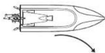
Forward

- Pull back the throttle trigger of the transmitter and the boat goes forward.
Backward

- Push forward the throttle trigger of the transmitter and the boat goes backward.
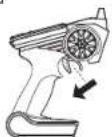
Turn Left

- Pull back the throttle trigger of the transmitter, and twist the rudder knob towards counterclockwise direction and the boat turns left.
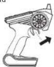
Turn Right
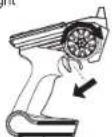
4. Pull back the throttle trigger of the transmitter, and twist the rudder knob towards clockwise direction and the boat turns right.

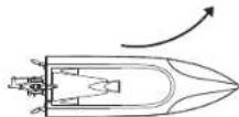
- If the boat capsizes in the water, push forward the throttle trigger of the transmitter and then pull back at once and the boat will return to normal.

- If the boat drifts to right, press the left rudder trim of the transmitter the and the boat will back to correct rudder slowly and sails straightly.
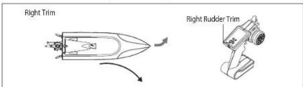
- If the boat drifts to left, press the right rudder trim of the transmitter the and the boat will back to correct rudder slowly and sails straightly.
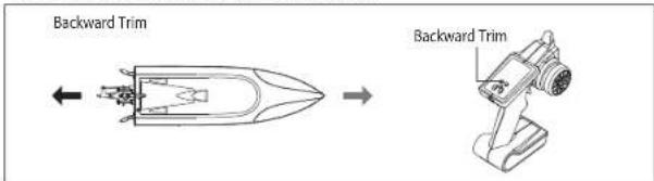
- If the boat still goes forward when the throttle trigger of the transmitter back to middle, press backward trim till the boat stop going forward.

- If the boat still goes backward when the throttle trigger of the transmitter back to middle, press forward trim till the boat stop going backward.
Spare Parts
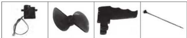
natural_image
Four black-and-white product images showing mechanical parts: a motor, fan blade, handle, and rod (no text or symbols visible)SLRBT10-01 SLRBT10-02 SLRBT10-03
SLRBT10-04
Steering Engine Propeller Tail Rudder
Screw Rod

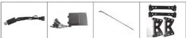
natural_image
Four grayscale images of different mechanical components: a rod, a boat, a bow, and a lever (no text or symbols visible)SLRBT10-05
Steel Pipe
SLRBT10-06
Cabin Cover
Li BatteryHull
natural_image
Four-panel image showing different types of electronic components: cable, battery pack, diagonal rod, and bracket (no text or symbols visible)SLRBT10-09
SLRBT10-10 SLRBT10-11 SLRBT10-12
USB Wire
Circuit Board Steering Engine Rod Support Holder

natural_image
Four-panel image showing mechanical components: two cylindrical rods, a dome-shaped component, a coiled cable, and a motor with wiring (no text or symbols visible)SLRBT10-15SLRBT10-13 SLRBT10-16SLRBT10-14
Motor
Silicone Waterproof RingTail Rubbolding Pipe
Compass Tube
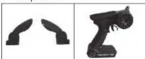
SLRBT10-18SLRBT10-17
Navigation Rudder Transmitter

MADE IN CHINA
Brand : SereneLife
Model : SLRBT10
Category : Radio