PFS4218-16GT2GF-240 - Network switch Dahua Technology - Free user manual and instructions
Find the device manual for free PFS4218-16GT2GF-240 Dahua Technology in PDF.

User questions about PFS4218-16GT2GF-240 Dahua Technology
0 question about this device. Answer the ones you know or ask your own.
Ask a new question about this device
Download the instructions for your Network switch in PDF format for free! Find your manual PFS4218-16GT2GF-240 - Dahua Technology and take your electronic device back in hand. On this page are published all the documents necessary for the use of your device. PFS4218-16GT2GF-240 by Dahua Technology.
USER MANUAL PFS4218-16GT2GF-240 Dahua Technology
16/24-Port Gigabit Managed PoE Switch
Quick Start Guide

natural_image
Abstract geometric shape with gray and blue color blocks (no text or symbols)Foreword
General
This manual introduces the functions and operations of 16/24-port Gigabit managed PoE switch (hereinafter referred to as "the Device").
Safety Instructions
The following categorized signal words with defined meaning might appear in the manual.
| Signal Words | Meaning | |
 | DANGER | Indicates a high potential hazard which, if not avoided, will result in death or serious injury. |
 | WARNING | Indicates a medium or low potential hazard which, if not avoided, could result in slight or moderate injury. |
 | CAUTION | Indicates a potential risk which, if not avoided, could result in property damage, data loss, lower performance, or unpredictable result. |
 | TIPS | Provides methods to help you solve a problem or save you time. |
 | NOTE | Provides additional information as the emphasis and supplement to the text. |
Revision History
| Version | Revision Content | Release Time |
| V1.0.0 | First release. | September 2020 |
| V1.0.1 | Updated "1.1 Product Introduction" and "1.2 Product Features". | November 2020 |
occurring when using the device.
- If there is any uncertainty or controversy, we reserve the right of final explanation.
Important Safeguards and Warnings
The manual helps you to use our product properly. To avoid danger and property damage, read the manual carefully before using the product, and we highly recommend you to keep it well for future reference.
Operating Requirements
- Do not expose the device directly to the sunlight, and keep it away from heat.
- Do not install the device in the damp environment, and avoid dust and soot.
- Make sure the device is in horizontal installation, and install the device on solid and flat surface to avoid falling down.
- Avoid liquid spattering on the device. Do not place object full of liquid on the device to avoid liquid flowing into the device.
- Install the device in the well-ventilated environment. Do not block the air vent of the device.
- Use the device at rated input and output voltage.
- Do not dissemble the device without professional instruction.
- Transport, use, and store the device in allowed ranges of humidity and temperature.
- Disconnect the power supply first to avoid personal injury when removing the cable.
- Voltage stabilizer and lightning arrester are optional according to site power supply and surrounding environment.
Power Supply Requirements
- Use the battery properly to avoid fire, explosion, and other dangers.
- Replace the battery with battery of the same type.
- Use locally recommended power cord in the limit of rated specifications.
- Use the standard power adapter. We will assume no responsibility for any problems caused by nonstandard power adapter.
- The power supply shall meet the SFI V requirement. Use the power supply that conforms to
environment, crush, puncture, cut or incinerate.
- Dispose of the battery as required by local ordinances or regulations.
Table of Contents
Foreword .... I
Important Safeguards and Warnings.... III
1 Overview....1
1.1 Product Introduction....1
1.2 Product Features.... 1
1.3 Typical Application.... 1
2 Device Structure....3
2.1 Front Panel....3
2.2 Rear Panel 4
3 Installation....5
3.1 Installing the Device 5
3.2 Wiring 5
3.2.1 Ethernet Port 5
3.2.2 Console Port 6
3.2.3 SFP Port 7
3.2.4 GND 7
4 Quick Operations 8
4.1 First Login by Console Port......8
4.2 Device Factory Default Configuration.... 10
4.3 VLAN Configuration....10
Appendix 1 Cybersecurity Recommendations....12
1 Overview
1.1 Product Introduction
The 16/24-Port Gigabit Managed PoE Switch is designed and developed for field transmission application of high definition video. The product is equipped with high performance switching engine and large buffer, which features low transmission delay and high reliability.
With solid and sealed all-metal case design, the product has low power consumption. With a fan inside which improves high surface heat dissipation efficiency, the product can work in the environment from -10^ C to 55^ C. And power input end overcurrent, overvoltage, and EMC protection can effectively resist the interference from static electricity, lightning, and pulse.
The product owns powerful network management function. Network management system supports iLinksView, CLI, web, and network management software based on SNMP.
1.2 Product Features
- Layer 2 network management PoE switch
• Support IEEE802.3af, IEEE802.3at standard - Port 1 and port 2 support IEEE802.3bt, and are compatible with Hi-PoE
• Network redundancy: STP/RSTP/MSTP
• Support IPv4/IPv6, and DHCP
• Network management based on SNMP - Configuration: web console, Telnet, CLI command
• QoS (IEEE802.1p/1Q), CoS/ToS to increase determinism - Enhanced network security with IEEE802.1X, SNMP v1/v2c/v3, HTTPS, and SSH
• Large data buffer up to 4 MB, real-time transmission
MAO code should be used to MAO address list consensus is OK
Figure 1-1 Networking

flowchart
graph TD
    A["Data Center Storage"] --> B["Internal Network"]
    C["Screen Controller"] --> B
    D["PC"] --> B
    E["PC"] --> B
    F["PC"] --> B
    G["PC"] --> B
    H["PC"] --> B
    I["PC"] --> B
    J["PC"] --> B
    K["PC"] --> B
    L["PC"] --> B
    M["PC"] --> B
    N["PC"] --> B
    O["PC"] --> B
    P["PC"] --> B
    Q["PC"] --> B
    R["PC"] --> B
    S["PC"] --> B
    T["PC"] --> B
    U["PC"] --> B
    V["PC"] --> B
    W["PC"] --> B
    X["PC"] --> B
    Y["PC"] --> B
    Z["PC"] --> B
    AA["PC"] --> B
    AB["PC"] --> B
    AC["PC"] --> B
    AD["PC"] --> B
    AE["PC"] --> B
    AF["PC"] --> B
    AG["PC"] --> B
    AH["PC"] --> B
    AI["PC"] --> B
    AJ["PC"] --> B
    AK["PC"] --> B
    AL["PC"] --> B
    AM["PC"] --> B
    AN["PC"] --> B
    AO["PC"] --> B
    AP["PC"] --> B
    AQ["PC"] --> B
    AR["PC"] --> B
    AS["PC"] --> B
    AT["PC"] --> B
    AU["PC"] --> B
    AV["PC"] --> B
    AW["PC"] --> B
    AX["PC"] --> B
    AY["The Monitoring Center"]
2 Device Structure
2.1 Front Panel
16-Port Gigabit Managed PoE Switch
Figure 2-1 Front panel

text_image
1 2 3 4 5 6 7 8 9Table 2-1 Front panel description
| No. | Name | Description |
| 1 | RJ45 port | Ethernet port, supports 10/100/1000 M self-adaptive. |
| 2 | COMBO port | 2 Ethernet ports, support 10/100/1000 M self-adaptive; 2 optical ports, support 1000 M self-adaptive. |
| 3 | Reset button | Long press the button for 5 s to reset the Device and recover default configuration. |
| 4 | Console serial port | Device debugging port. |
| 5 | PoE power usage indicator | Current power consumption display. |
| 6 | Downlink indicator | Current port link status and PoE status. |
| 7 | Uplink port indicator | Link/Act indicator. |
| System status: | ||
| 2 | COMBO port | 2 Ethernet ports, support 10/100/1000 M self-adaptive; 2 optical ports, support 1000 M self-adaptive. |
| 3 | Reset button | Long press the button for 5 s to reset the Device and recover default configuration. |
| 4 | Console serial port | Device debugging port. |
| 5 | PoE power usage indicator | Current power consumption display. |
| 6 | Downlink indicator | Current port link status and PoE status. |
| 7 | Uplink port indicator | Link/Act indicator. |
| 8 | System indicator | System status:When device is booting up, the light is flashing quickly.When device is working properly, the light is flashing slowly. |
| 9 | Power indicator | Current power status of the Device. |
2.2 Rear Panel

text_image
Figure 2-3 Rear panel 1 2 3Table 2-3 Rear panel description
| No. | Name | Description |
3 Installation
3.1 Installing the Device
The device supports standard rack mount. Install the rack mount kit on both sides of the switch. See Figure 3-1.
Figure 3-1 Rack mount

text_image
10-Port And Security Manager Switch 10-Port And Security Manager Switch 10-Port And Security Manager Switch 10-Port And Security Manager Switch 10-Port And Security Manager Switch 10-Port And Security Manager Switch 10-Port And Security Manager Switch 10-Port And Security Manager Switch 10-Port And Security Manager Switch 10-Port And Security Manager Switch 10-Port And Security Manager Switch 10-Port And Security Manager Switch3.2 Wiring
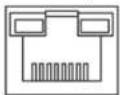
3.2.1 Ethernet Port
Figure 3-2 Ethernet port pin number

10/100/1000 M Base-T Ethernet port adopts standard RJ45 port. Equipped with self-adaptation function, it can be automatically configured to full duplex/half-duplex operation mode, and supports MDI/MDI-X self-recognition function of the cable, which means that the switch can use cross-over cable or straight-through cable to connect terminal device to network device.
Figure 3-3 Pin description
3.2.2 Console Port
Figure 3-4 Console port
See Figure 3-4 for console port. The switch console port and computer controlling 9-pin serial port are connected with RJ-45-DB9 cable. You can call the console software of the device by operating the superterminal software of the Windows system for device configuration, maintenance, and management.
See Figure 3-5 for cable sequence of RJ-45-DB9.
Figure 3-5 Cable sequence of RJ45 DB9

text_image
A DB9 Plug 5 9 6 1 A B RJ45 Connector 8 1 Cable Sequence TXD 3——3 RXD RXD 2——2 TXD GND 5——5 GNDOne end of RJ45 DB9 cable is RJ45 connector, which needs to be inserted into the console port of the device. And the other end is DB9 plug, which needs to be inserted into the computer controlling 9-pin serial port.
Table 3-1 Pin description
| DB9 pin | RJ45 pin | Signal | Description |
| D17 |
3.2.3 SFP Port

The signal is transmitted through laser by optical fiber cable. The laser conforms to the requirement of level 1 laser products. To avoid injury of eyes, do not look at the 1000 Base-X optical port directly when the device is powered on.
Figure 3-6 SFP module structure
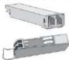
Figure 3-7 SFP module installation
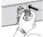
Installing SFP Port
Before installing SFP module, wear antistatic gloves, and then wear antistatic wrist strap. Make sure that the antistatic gloves and the antistatic wrist strap are in good contact.
- Lift the handle of SFP module upward vertically, and stuck it to the top hook.
- Hold the SFP module by both sides, and push it gently into the SFP slot till the SFP module is firmly connected to the slot (both the top and bottom spring strip of the SFP module are firmly stuck with the SFP slot).
3.2.4 GND
4 Quick Operations
We will introduce VLAN configuration briefly in this section. See the corresponding command line manual for detailed configuration.
4.1 First Login by Console Port
It is the most basic way to log in to the local interface via Console port, and it is also the method to configure other ways to log in to the device.
Step 1 Power off the PC.
Step 2 Use default console port cable to connect PC and the device.
First insert the DB-(hole) plug of console port cable into the 9-pin serial port of PC, and then insert the RJ45 plug into the console port of the device.

- Confirm the sign on the port during connection, in case it may plug into the wrong port.
- Plug out RJ45 and then DB-9 when dismantling console port cable.
Figure 4-1 Login via console port

RS-232
Console port

Console Port Cable
Switch
PC
Step 3 Power on the PC.
Step 4 Run terminal simulation program on the PC and then select the serial port which is to
Step 6 Enter username and password, and then press Enter.
[Non-Text]
The default username is admin, and the default password is admin.
The following command line prompt (SWITCH#) is displayed after pressing Enter, which means login has been successful.
Enter corresponding command, and you can configure the device or check device operating status, and you can enter ? anytime if you need help.
+M25PXX : Init device with JEDEC ID 0xC22018.
Luton10 board detected (VSC7428 Rev. D).
RedBoot(tm) bootstrap and debug environment [ROMRAM]
Non-certified release, version 1_31-4752 - built 17:29:35, Jul 29 2017
Copyright (C) 2000, 2001, 2002, 2003, 2004, 2005, 2006, 2007, 2008, 2009
Free Software Foundation, Inc.
RedBoot is free software, covered by the eCos license, derived from the GNU General Public License. You are welcome to change it and/or distribute copies of it under certain conditions. Under the license terms, RedBoot's source code and full license terms must have been made available to you.
Redboot comes with ABSOLUTELY NO WARRANTY.
Platform: VCore-III (MIPS32 24KEc) LUTON26
RAM: 0x80000000-0x88000000 [0x80028f20-0x87fdfffc available]
FLASH: 0x40000000-0x40ffffff, 256 x 0x10000 blocks
== Executing boot script in 3.000 seconds - enter ^C to abort
RedBoot> diag -p
RedBoot> fis load -x linux
MD5 signature validated
Stage1: 0x80100000, length 4641272 bytes
W icfg 18:00:22 71/icfg_commit_tftp_load_and_trigger#2695: Warning: TFTP get bringup-config: Operation timed out.
Press ENTER to get started
Username: admin
Password:
SWITCH#

Enter corresponding command to configure the device or check device operating status, and you can enter ? anytime if you need help.
4.2 Device Factory Default Configuration
You can log in to Web interface of the device via the following IP address.
Username and password can be applied to log in to Web interface via Console port.
Table 4-1 Device factory default
| Parameter | Note |
| IP address | 192.168.1.110 |
| Username | admin |
| Password |

- iLinksView is enabled by default, and the default username is admin, the default password is It_91_il_02_nmp.
ID when creating VLAN, ranging from 2 to 4094. The switch creates VLAN1 by default and VLAN1 cannot be deleted.
Application Example
Networking Requirement
There are two users, user 1 and user 2. These two users need to be in different VLAN due to different network function and environment. User 1 belongs to VLAN2, connecting to switch port G1/1 (Gigabit Ethernet 1/1); user 2 belongs to VLAN 3, connecting to switch port G1/2 (Gigabit Ethernet 1/2).
Figure 4-2 VLAN networking

flowchart
graph TD
    A["Switch"] -->|G1/1| B["User 1 VLAN2"]
    A -->|G1/2| C["User 2 VLAN3"]
Configuration Steps
The switch configuration is shown as follows.
- Log in to the device. Refer to "4.1 First Login by Console Port".
- Run the following command to create VLAN.
Appendix 1 Cybersecurity Recommendations
Cybersecurity is more than just a buzzword: it's something that pertains to every device that is connected to the internet. IP video surveillance is not immune to cyber risks, but taking basic steps toward protecting and strengthening networks and networked appliances will make them less susceptible to attacks. Below are some tips and recommendations on how to create a more secured security system.
Mandatory actions to be taken for basic device network security:
1. Use Strong Passwords
Please refer to the following suggestions to set passwords:
- The length should not be less than 8 characters;
- Include at least two types of characters; character types include upper and lower case letters, numbers and symbols;
- Do not contain the account name or the account name in reverse order;
- Do not use continuous characters, such as 123, abc, etc.;
- Do not use overlapped characters, such as 111, aaa, etc.;
2. Update Firmware and Client Software in Time
- According to the standard procedure in Tech-industry, we recommend to keep your device (such as NVR, DVR, IP camera, etc.) firmware up-to-date to ensure the system is equipped with the latest security patches and fixes. When the device is connected to the public network, it is recommended to enable the “auto-check for updates” function to obtain timely information of firmware updates released by the manufacturer.
- We suggest that you download and use the latest version of client software.
"Nice to have" recommendations to improve your device network security:
1. Physical Protection
We suggest that you perform physical protection to device, especially storage devices. For example, place the device in a special computer room and cabinet, and implement well-done access control permission and key management to prevent unauthorized
6. Enable HTTPS
We suggest you to enable HTTPS, so that you visit Web service through a secure communication channel.
7. MAC Address Binding
We recommend you to bind the IP and MAC address of the gateway to the device, thus reducing the risk of ARP spoofing.
8. Assign Accounts and Privileges Reasonably
According to business and management requirements, reasonably add users and assign a minimum set of permissions to them.
9. Disable Unnecessary Services and Choose Secure Modes
If not needed, it is recommended to turn off some services such as SNMP, SMTP, UPnP, etc., to reduce risks.
If necessary, it is highly recommended that you use safe modes, including but not limited to the following services:
- SNMP: Choose SNMP v3, and set up strong encryption passwords and authentication passwords.
- SMTP: Choose TLS to access mailbox server.
- FTP: Choose SFTP, and set up strong passwords.
- AP hotspot: Choose WPA2-PSK encryption mode, and set up strong passwords.
10. Audio and Video Encrypted Transmission
If your audio and video data contents are very important or sensitive, we recommend that you use encrypted transmission function, to reduce the risk of audio and video data being stolen during transmission.
Reminder: encrypted transmission will cause some loss in transmission efficiency.
11. Secure Auditing
- Check online users: we suggest that you check online users regularly to see if the device is logged in without authorization.
- Check device log: By viewing the logs, you can know the IP addresses that were used to log in to your devices and their key operations.
12 Network Log