KNC-LNDI45B - Security Camera KT&C - Free user manual and instructions
Find the device manual for free KNC-LNDI45B KT&C in PDF.

User questions about KNC-LNDI45B KT&C
0 question about this device. Answer the ones you know or ask your own.
Ask a new question about this device
Download the instructions for your Security Camera in PDF format for free! Find your manual KNC-LNDI45B - KT&C and take your electronic device back in hand. On this page are published all the documents necessary for the use of your device. KNC-LNDI45B by KT&C.
USER MANUAL KNC-LNDI45B KT&C
IP DOME CAMERA Megapixel Network Camera
USER MANUAL

natural_image
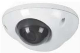
Two identical white surveillance cameras with black lenses, shown from different angles (no text or symbols visible)Network Dome Camera User's Manual
About This Document
This manual is intended for administrators and users of the IP CAMERA. It includes instructions for using and managing the Network Camera on your network. Previous experience of networking will be of use when installing and using this product. Some knowledge of UNIX or Linux-b as ed systems would also be beneficial, for developing shell scripts and applications. Later versions of this document will be posted to the NV Website, as required. See also the product's online help, available via the Web-based interface.
Safety Notices Used In This Manual
Caution! - Indicates a potential hazard that can damage the product. Important! - Indicates a potential hazard that can seriously impairs operation. Do not proceed beyond any of the above notice until you have fully understood the implications.
Legal Considerations
Camera and audio surveillance can be prohibited by laws that vary from country to country. Check the laws in your local region before using the product for surveillance purposes.
Electromagnetic Compatibility
This equipment generates, uses, and can radiate radio frequency energy and, if not installed and used in accordance with the instructions, may cause harmful interference to radio communications. However, there is no guarantee that interference will not occur in a particular installation. If this equipment does cause harmful interference to radio or television reception, which can be determined by turning the equipment off and on, the user is encouraged to try to correct the interference by using the equipment off and on. The equipment has been used to ensure that the separation between the equipment and receiver. Connect the equipment to an outlet on a different circuit to the receiver. Consult your dealer or an experienced radio/TV technician for help. Shielded (STP) network cables must be used with this unit to ensure compliance with EMC standards.
USA – This equipment has been tested and found to comply with the limits for a Class A digital device, pursuant to Part 15 of the FCC Rules.
These limits are designed to provide reasonable protection against harmful interference when the equipment. This equipment generates, uses, and can radiate radio frequency energy and, if not installed and used in accordance with the instruction manual, may cause harmful interference to radio co mm un ic ations. Operation of this equipment in a residential area is likely to cause harmful interference in which case the user will be required to correct the interference at his own expense.
WARNING
This is a class A product. In a domestic environment this product may cause radio interference in which case the user may be required to take adequate measures.
Europe – This digital equipment fulfills the requirements for radiated emission according to Class A of EN55022/2006, and the requirements for immunity according to EN55024/1998 residential, commercial, and light industry.
Liability
Every care has been taken in the preparation of this manual; please inform your local NV office of any inaccuracies or omissions. NV Co., Ltd. cannot be held responsible for any technical or typographical errors and reserves the right to make changes to the product and manuals without prior notice. NV Co., Ltd. makes no warranty for any kind with regard to the material contained within the document. Includes all other information and fitness for a particular purpose. NV Co., Ltd. shall not be liable nor responsible for incidental or consequential damages in connection with the furnishing, performance or use of this material.
Network Dome Camera User's Manual
Cautions
This device complies with Part 15 of the FCC Rules.
Operation is subject to the following two conditions:
-
This device may not cause harmful interference.
-
This device must accept any interference received, including interference that may cause undesired operation.
Note
This equipment has been tested and found to comply with the limits for a Class A digital device, pursuant to part 15 of the FCC Rules. These limits are designed to provide reasonable protection against harmful interference when the equipment is operated in a commercial environment. This equipment generates, uses, and can radiate radio frequency energy and, if not installed and used in accordance with the instruction manual, may cause harmful interference to radio communications. Operation of this equipment in a residential area is likely to cause harmful interference in which case the user will be required to correct the interference at his own expense.
WARNING
This is a class A product. In a domestic environment this product may cause radio interference in which case the user may be required to take adequate measures.
Caution
Any changes or modifications in construction of this devices which are not expressly approved by the party responsible for compliance could void the user's authority to operate the equipment.
CAUTION
- A regulated DC12V 1A power supply is recommended for use with this camera for the best picture and the most stable operation. An unregulated power supply can cause damage to the camera. When an unregulated power supply is applied, product warranty will be
- It is recommended that the camera be used with a monitor that has a CCTV quality 75 video impedance level. If your monitor is switched to high impedance then please adjust accordingly.
- Do not attempt to disassemble the camera to gain access to the internal components. Refer servicing to your dealer.
- Never face the camera towards the sun or any bright or reflective light, which may cause smear on the picture and possible damage to the Image Sensor.
- Do not remove the serial sticker for the warranty service.
- Do not expose the camera to rain or other types of liquid.
- The apparatus must be connected to a mains socket-outlet with a protective earthing connection.

WEEE (Waste Electrical & Electronic Equipment)
This marking shown on the product or its literature, indicates that it should not be disposed with other household wastes at the end of its working life. To prevent possible harm to the environment or human health from uncontrolled waste disposal, please separate this from other types of wastes and recycle it responsibly to promote the sustainable reuse of material resources. Household users should contact either the retailer where they purchased this product, or their local government office, for details of where and how they can take item for environmentally safe recycling.
IMPORTANT SAFETY INSTRUCTIONS
1) Read these instructions.
2) Keep these instructions.
3) Heed all warnings.
4) Follow all instructions.
5) Do not use this apparatus near water.
6) Clean only with dry cloth.
7) Do not block any ventilation openings. Install in accordance with the manufacturer's instructions.
8) Do not install near any heat sources such as radiators, heat registers, stoves, or other apparatus (including amplifiers) that produce heat.
9) Do not defeat the safety purpose of the polarized or grounding-type plug. A polarized plug has two blades with one wider than the other. A grounding type plug has two blades and a third grounding prong. The wide blade or the third prong are provided for your safety. If the provided plug does not fit into your outlet, consult an electrician for replacement of the obsolete outlet.
10) Protect the power cord from being walked on or pinched particularly at plugs, convenience receptacles, and the point where they exit from the apparatus.
11) Only use attachments/accessories specified by the manufacturer.
12) Use only with the cart, stand, tripod, bracket, or table specified by the manufacturer, or sold with the apparatus. When a cart is used, use caution when moving the cart/apparatus combination to avoid injury from tip-over.

13) Unplug this apparatus during lightning storms or when unused for long periods of time.
14) Refer all servicing to qualified service personnel. Servicing is required when the apparatus has been damaged in any way, such as power-supply cord or plug is damaged, liquid has been spilled or objects have fallen into the apparatus, the apparatus has been exposed to rain or moisture, does not operate normally, or has been dropped.
Table of Contents
CAUTIONS 3
IMPORTANT SAFETY INSTRUCTIONS 4
OVERVIEW 6
USING THE NETWORK CAMERA 9
CONFIGURING THE NETWORK CAMERA 13
BASIC > NETWORK 14
BASIC > USERS 15
BASIC > VIDEO > COMMON 16
BASIC > VIDEO > H.264 17
BASIC > VIDEO > MJPEG 18
BASIC > DATE & TIME 19
ADVANCED > CAMERA SETTING 20
ADVANCED > EVENT SERVER 21
ADVANCED > EVENT ACTIONS 22
Action configuration for [Motion Detection + Upload Image + FTP] 24
Action configuration for [Motion Detection + Upload Image + E-mail] 25
Action configuration for [Motion Detection + Activate output] 26
Action configuration for [Motion Detection + E-mail Notification] 27
Action configuration for [Sensor Input + Upload Image + FTP] 28
Action configuration for [Sensor Input + Upload Image + E-mail] 29
Action configuration for [Sensor Input + Activate Output] 30
Action configuration for [Sensor Input + E-mail Notification] 31
Action configuration for [Manual Trigger + Upload Image + FTP] 32
Action configuration for [Manual Trigger + Upload Image + E-mail] 33
Action configuration for [Manual Trigger + Activate Output] 34
Action configuration for [Manual Trigger + E-mail Notification] 35
Action configuration for [Network Fail + Activate Output] 36
Action configuration for [Reboot] 37
ADVANCED > MOTION SETTINGS 38
ADVANCED > SMTP 40
ADVANCED > ADVANCED NETWORK 41
ADVANCED > HTTPS 43
ADVANCED > MASK 45
ADVANCED > LIVE VIEW LAYOUT 47
ADVANCED > IP ADDRESS FILTER 48
MAINTENANCE > INITIALIZE & UPGRADE 49
MAINTENANCE > LOGS 50
SUPPORT > SYSTEM / HELP 51
PRODUCT SPECIFICATIONS 52
TROUBLESHOOTING 54
GLOSSARY
Network Dome Camera User's Manual
Overview
Features
Thank you for purchasing a KT&C network surveillance product.
KT&C KNC-LDDi45, KNC-LNDi45, is a high-performance, Megapixel Network Camera which offers the perfect solution for integrating network-based video surveillance systems.
natural_image
Close-up of a white surveillance camera with a dark lens (no visible text or symbols)KNC-LDDi45 KNC-LNDi45

natural_image
Close-up of a white surveillance camera with a circular lens (no visible text or symbols)Key Features
- Onvif 1.0
- Simultaneous H.264 and MJPEG video streams at up to 30 fps in 1920x1080 resolution (KNC-LDDi45, KNC-LNDi45)
- Power over Ethernet (PoE Class 3)
- Multi-area motion detection
- Powerful event management
- Upgradeable firmware
- IR LED 15ea(KNC-LNDi45)
System requirements for a PC
Product Description
Description and function
- KNC-LNDi45
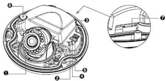
text_image
Technical diagram of a mechanical device with numbered components and an inset close-up view- KNC-LDDi45

text_image
Technical diagram showing labeled parts of a car body with numbered annotationsProduct Description
Description and function
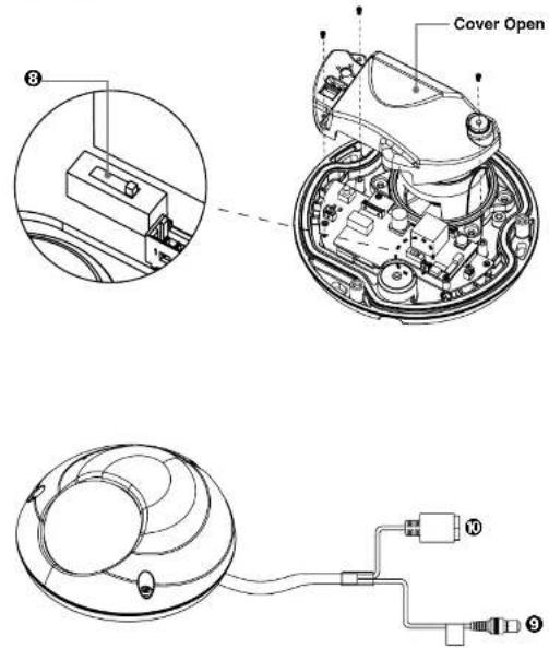
text_image
Cover Open ③ ⑩ ⑨- Infrared LED – These LEDs emit infrared radiations.
- Reset Button - Press the reset switch for more than 10 seconds,
Using the Network Camera
The Network Camera can be used with either Internet Explorer or Central Monitoring System (CMS) in Microsoft Windows operating systems. Note: For information on installing the Network Camera, please refer to the Installation Guide.
Accessing the Network Camera
- Start your browser.
* When you run or install ActiveX, open the Internet Explorer browser as Administrator on Windows Vista, 7, 8 (supported only in the Desktop mode). Users without administrator rights cannot install ActivX controls. Unless Internet explorer is opened as administrator, The camera functions of Live Web Viewer cannot work(screen capture, etc.)
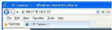
- Enter the IP address or host name of the Network Camera in the Address field.
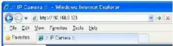
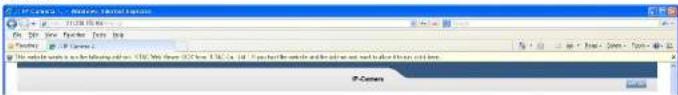
- If you are accessing the Network Camera for the first time, you will see the warning message as shown below.
text_image
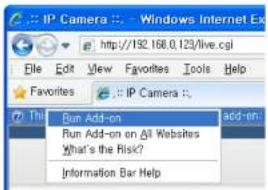
PC-CAMOS - Microsoft Excel Options File Edit View Insert Tools Help C:\Program Files\Microsoft Excel\PC-CAMOS\PC-CAMOS\PC-CAMOS\PC-CAMOS\PC-CAMOS\PC-CAMOS\PC-CAMOS\PC-CAMOS\PC-CAMOS\PC-CAMOS\PC-CAMOS\PC-CAMOS\PC-CAMOS\PC-CAMOS\PC-CAMOS\PC-CAMOS\PC-CAMOS\PC-CAMOS\PC-CAMOS\PC-CAMOS\PC-CAMCS PC-Camos- Click the warning message and select "Run Add-on" or "Install ActiveX Control..." etc.
text_image
IP Camera : Windows Internet Ex http://192.168.0.123/live.cgi File Edit View Favorites Tools Help Favorites : IP Camera :. This Run Add-on add-on: Run Add-on on All Websites What's the Risk? Information Bar HelpUsing the Network Camera
- If the Windows Security Alert pop-up window appears, click the "Unblock" Button.

text_image
Windows Security Alert To help protect your computer. Windows Firewall has blocked some features of this program. Do you want to keep blocking this program? Name: Internet Explorer Publisher: Microsoft Corporation Keep Blocking Unlock Ask Me Later Windows Firewall has blocked this program from accepting connections from the Internet or a network. If you recognize the program or trust the publisher, you can unlock it. When should I unlock a program?- After installing the ActiveX Control, a Login page will be displayed. Enter the user ID and password.
Note: Default User ID and Password is [ID: admin, Password: admin]

text_image
IP CAMERA User ID Password LOGINUsing the Network Camera
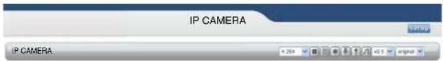
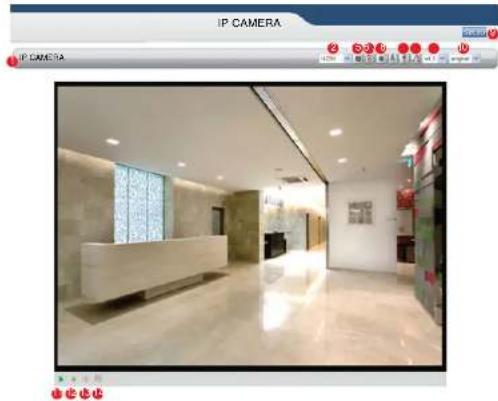
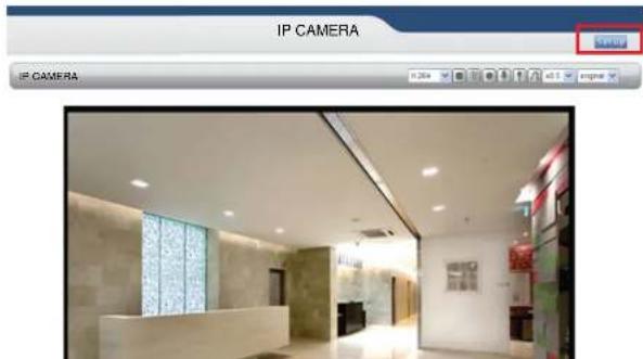
- The video image will be displayed in your browser.
text_image
IP CAMERA IP CAMERA
natural_image
Interior view of a modern hotel lobby with marble flooring, reception desk, and glass ceiling (no visible text or signage)▶ 4.5月
Important: To view streaming video in Microsoft Internet Explorer, you must set your browser to allow the Web Viewer to be installed on your computer. This ActiveX component will be installed when you access the camera for the first time.
Using the Network Camera
Live View page
If the Network Camera has been customized on Setup>Advanced>Live View Layout, the buttons and other items shown below may or may not be displayed on the Live View page. The following diagram provides an overview of each available button.
natural_image
Interior view of a modern reception area with marble flooring and reception desk (no visible text or symbols)- Host Name – Displays the host name.
- Video Format – The Video Format drop-down list allows the video format to change instantly on the Live View page.
- Play/Stop – The Play/Stop button starts and stops the media stream.
- Snapshot – The Snapshot button takes a snapshot of the live image. The target directory for saving snapshots is .../My document//Snapshots
- Record – The Record button is used to record the current video stream to the local hard drive. The target directory for saving video clip is .../My document//Video Note: Video recording will be terminated automatically after 5 minutes.
- Manual Trigger – The Manual Trigger button triggers an event directly from the Live View page. Click this button to manually start the events instantly.
7 Active/Inactive - Click this button to manually start and stop the device which is connected to
Configuring the Network Camera
This section describes how to configure the Network Camera and is intended for:
- Administrators, who have unrestricted access to the entire Setup menu.
- Operators, who have access to the Video & Image, Audio, and Event Configuration settings.
The Network Camera is configured from the Setup menu in a standard web browser.
Accessing the Setup menu
Follow the instructions below to access the Setup menu from a browser.
- Start the browser and enter the IP address or host name of the Network Camera in the location / address field.
- The Live View page is now being displayed. Click Setup to display the Setup menu.
natural_image
Interior view of a modern office lobby with reception desk and wall-mounted screens (no visible text or symbols)Configuring the Network Camera
Basic > Network
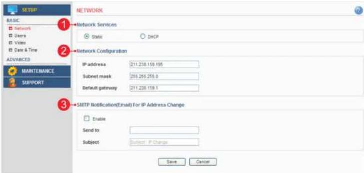
This section describes the basic network settings and SMTP notification. If the SMTP notification feature is enabled, user can receive an IP change notification by e-mail when the IP address is changed by the DHCP server.
text_image
BASIC Network Services Static DHCP Network Configuration IP address 211.238.159.195 Subnet mask 255.255.255.0 Default gateway 211.238.159.1 SMTP Notification(Email) For IP Address Change Enable Send to Subject Subject IP Change Save Cancel1. Network Services
A. Static – Assigns a static IP address manually.
B. DHCP – Assigns a dynamic IP address automatically from the DHCP server on your network. Important: DHCP should be enabled only if you are using the SMTP notification for the IP address change, or if your DHCP server can update a DNS server, which allows you to access the Network Camera by the host name. If DHCP is enabled and you cannot access the unit, then you may have to reset the unit to the factory default and redo the installation again.
2. Network Configuration
A. IP Address – Specify a unique IP address for your Network Camera.
B. Subnet mask – Specify the mask of the Network Camera located subnet.
C. Default gateway – Specify the IP address of the default gateway (router) used for connecting devices to the network.
Network Dome Camera User's Manual
Configuring the Network Camera
Basic > Users
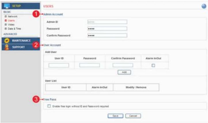
This section describes the administrator and user account settings. Each user can be configured to different authority levels.
text_image
BASIC Network Users Video Date & Time ADVANCED MAINTENANCE SUPPORT USERS Admin Account Admin ID: admin Password ****** Confirm Password ****** User Account Add User User ID Password Confirm Password Alarm Inv/Out Add User List User ID Alarm Inv/Out Modify / Remove Free Pass Enable free logn without ID and Password required Save Cancel1. Admin Account
A. Admin ID - Enter the administrator ID.
B. Admin Password – Enter the administrator password.
Important: Factory default value is ID: admin, Password: admin
Network Dome Camera User's Manual
Configuring the Network Camera
Basic > Video > Common
This section the basic settings for video and audio.
Important: These setting values will affect the original video and images.

text_image
SETUP BAS:5C Service Users View & Audio Data & Time ADJAMIKERS RAVIMELMANCE SUPPORT ENCODE SETTING H.264 Resolution: 1500 x 1000 + Adding Output Encoder FPS: 30 Video Format: MTSC Flip & Rotate: Normal 4.254 Blonde control: CSR (Constant to Frame) Average Shields: 4200 pixels RPLPSG Resolution: 750 x 450 Encoder FPS: 30 pixels Flip & Rotate: Normal WPC3 Quality (1 - 101): 52 Text Display Setting Include data Include font size Place to output at Top Audio Input Create Audio Save Cancel Initiate- H.264
A. Resolution - Select the resolution to use for the H.264 and JPEG image.
Note: Date & time cannot be displayed when RESOLUTION is set with MJPEG(176x120)
B. Video Format – The analog video format.
C. Maximum Frame rate - This feature is used to limit the frame rate. The frame rate can be set by selecting values from the drop down list.
D. Flip & Rotate - Flip the picture.
- Bit Rate Control
A. Variable bit rate (VBR) - Set the Network Camera to produce a variable bit rate H.264 video.
Network Dome Camera User's Manual
Configuring the Network Camera
5. Text Overlay Settings
A. Include date – Includes date in the video image as configured.
B. Include time – Includes time in the video image as configured.
C. Include text – Enter your own text in the field to overlay text in the video image.
Note: The maximum number of characters in this field is 17 characters. You can see the whole text (max 17 characters) in the video image. But if you use 320x240 resolution, you can only view up to 2 characters.
D. Place text/date/time at – Select top or bottom position to display text, date, time.
6. Audio Settings
A. Enable Audio – Select to use the Audio.
Network Dome Camera User's Manual
Configuring the Network Camera
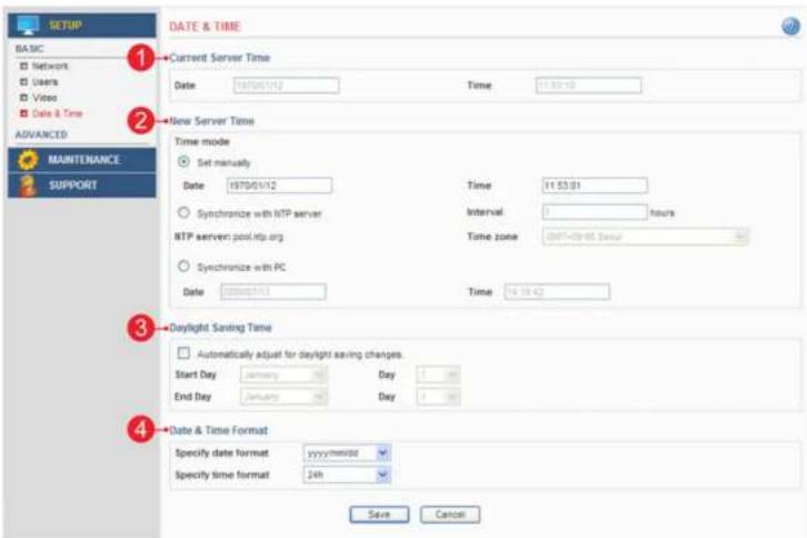
Basic > Date & Time
This section describes the date and time settings.
text_image
BASIC Networks Users Video Date & Time ADVANCED MAINTENANCE SUPPORT DATE & TIME Current Server Time Date 1970/01/12 Time 11:53:10 New Server Time Time mode Set manually Date 1970/01/12 Time 11:53:01 Synchronize with NTP server Interval 0 hours NTP server: pool.ntp.org Time zone GMT+28:05 Hour Synchronize with PC Date 2004/01/12 Time 16:18:42 Daylight Saving Time Automatically adjust for daylight saving changes. Start Day January Day 1 Day End Day January Day 1 Day Date & Time Format Specify date format yyyy/minute Specify time format 2nd Save Cancel1. Current Server Time
A. Date – Displays current date of Network Camera. B. Time – Displays current time of Network Camera.
2. New Server Time
A. Set manually – Using this option allows you to enter the time and date manually.
B. Synchronize with NTP server – The Network Camera will sync the time with a NTP server.
The NTP server's IP address or host name is specified in the Setup>Advanced Network>NTP Setting
Network Dome Camera User's Manual
Configuring the Network Camera
Advanced > Camera Setting
This section describes the advanced settings of the camera.

text_image
SETUP BASIC ADVANCED Camera Setting Level Server Event Action Option Setting SOTP Advanced Network HTTPS FTP Mask Live Line Laps P-Address Filter 10 CARD MAINTENANCE SUPPORT CAMERA SETTING Basic Settings Lens Type Fixed Lens Day Night Mode: Auto Day Night Control: nighted day:5 Day Night Delay Time: 0 Anti Flicker: 60Hz 10 MHz: 72 [0.255] Exposure Settings Exposure Target Factor: 100 [80-200%] Exposure Mode: Auto BLC: OFF Sensor Max Gain: 30dB (default) Shutter Speed: USB Image Adjustment Selection: 54 [0.255] Brightness: 128 [0.255] Contrast: 54 [0.255] Sharpness: 128 [0.255] White Balance Setting White Balance Contrast: Auto Save Cancel Amplification1. Basic Settings
A. Lens Type - The camera lens type.
B. Day and Night Mode – The day and night mode can be selected from the drop down list.
Auto – the camera will automatically switch between IR cut filter On and Off.
according to the current lighting conditions.
Color – the ip camera will always stay in color mode
Black and White – This camera will be able to "see" infrared light, e.g. at night.
thus making the image clearer.
C. Day Night Control – Adjust day and night lux level.
D. Day Night Delay Time - Adjust day and night delay time
E. Anti Flicker – This setting is used to remove 50/60 Hz flicker.
F. Digital Noise Reduction – The digital noise reduction can help depress noise under low light situation
but, also blur some of the image detail. So it is better to set this value higher
under low light situations, and set it lower under good light conditions.
2. Exposure Setting
Network Dome Camera User's Manual
Configuring the Network Camera
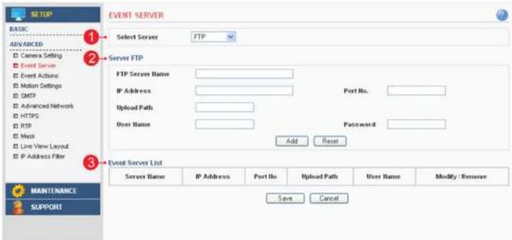
Advanced > Event Server
This section describes how to configure the event server used in the event action section.
text_image
EVENT SERVER Select Server FTP Server FTP FTP Server Name: IP Address: Upload Path: User Name: Add Reset Password: Event Server List Server Name IP Address Port No Upload Path User Name Modify / Remove Save Cancel BASIC ADVANCED Camera Setting Event Server Event Actions Motion Settings SMTP Advanced Network HTTPS RTP Mask Live View Layout IP Address Filter MAINTENANCE SUPPORT1. Select Server
A. Select the server type to configure. Configuration is only available for FTP servers.
2. Server FTP
- FTP Server Name – Enter a descriptive name.
- IP Address – Enter the server's IP address or host name.
Important: DNS server must be specified in the Setup>Advanced>Advanced network if you are using a host name. - Port No. – Enter the port number used by the FTP server. The default is 21.
- Upload Path – Specify the path to the directory where the uploaded images will be stored.
Note that a directory must be created in the FTP server before using this feature. - User Name – Enter the User ID.
- Password – Enter the Password.
2.5.10
Netto: Dome Camera Users Manual
Configuring the Network Camera
Advanced > Event Actions
This section describes how to configure the Network Camera for event handling. Various actions can be configured to run when certain types of event occur.

text_image
EVENT ACTIONS BASIC ADVANCED Camera Setting Event Server Event Actions Motion Settings DMTP Advanced Network HTTPS RTP Mask Live View Layout IP Address Filter PARTICUM 1 Trigger Action Type Event Name Use Enable Disable Select Upload Type Trigger Type Motion Detection Action Type Upload Image FTP FTP Selection Select FTP Server Server 1 Image Upload Setting Image frequency 5 fps Image Name Pre-trigger buffer 0 seconds Select the suffix Trigger Type DateTime Post-trigger buffer 0 seconds IP Address Schedule to respond on Trigger Schedule Always Sun Mon Tue Wed Thu Fri Sat Start Time End Time Add Reset Event List Event Enable Trigger Action Type Select Modify Copy Remove Save Cancel- Trigger / Action Type
Defines the trigger tune or action tune
Configuring the Network Camera
Prepare to configure event action
Event Servers are used for receiving uploaded image files and/or notification messages. To set up an Event server for your Network Camera, go to Setup > Advanced > Event Server or Setup > Advanced > SMTP and enter the required information according to the selected server type.
Note: When High image resolution and/or lower compression levels are used for uploading images to "FTP server" SMTP server, Individual Images may be missing. If this occurs, Lower image resolution and/or higher compression levels must be used for seamless uploading.
| Server Type Purpose Information required | ||
| FTP Server Receives uploaded images - Descriptive name of your choice- User Name and Password (to FTP server)- Upload path- Port number | ||
| E-mail (SMTP) Receives uploaded imagesReceives notification messages | - Descriptive name of your choice- User Name and Password (to SMTP server) | |
Variation of event action configuration
| Trigger Type Action Type Upload Type Consequence | ||
| Motion detection | Upload image FTP Upload images to FTP server | |
| E-mail Upload images via E-mail. | ||
| Activate output Activate digital output | ||
| E-mail notification Send a notification message | ||
| Sensor in Upload | Image FTP Upload images to FTP server | |
| E-mail Upload images via E-mail. | ||
| Activate output Activate digital output | ||
| E-mail notification Send a notification message | ||
| Manual Trigger | Upload image FTP Upload images to FTP server | |
| E-mail Upload images via E-mail. | ||
| Activate output Activate digital output | ||
| E-mail notification Send a notification message | ||
| Network Fail Activate Output Activate digital output. | ||
| Reboot | E-mail notification Send a notification message | |
Network Dome Camera Users Manual
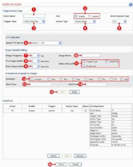
Configuring the Network Camera
Action configuration for [Motion Detection + Upload Image + FTP]
text_image
EVENT ACTIONS Trigger/Action Type Event Name Trigger Type User Detection Action Type Enable Show Select Options Type FTP FTP Selects Select FTP Server Server 1: 100 Image Upload Setting Image frequency Pre-trigger buffer Post-Stop In Fire Image Name Exceptional the suffix Trigger Type DataTime If action Schedule to respond to Trigger Schedule Max Time Always Pure True End Time End Time Event List Event Enable Trigger Action Type Select Configuration PP Show Show Name: Use Delete Trigger Type: Shower Action Type: Imp User Type: M8 First Pattern: M1 Post Connection: M24a Image Type: M2567 Image Name: M2639 Pre-Trigger Buffer: 3 seconds Post-Stop In Fire: 5 seconds Select the suffix: T = 0 - 0 Schedule: A= 10.00-20.00 OK Cancel Save Cancel- Enter a descriptive event name.
- Select "enable".
- Set the trigger type to motion detection.
- Set the action type to upload image.
- Set the upload type to FTP
- Select the FTP server that will receive uploaded image files.
- Select the image frequency. (frame per second)
Configuring the Network Camera
Action configuration for [Motion Detection + Upload Image + E-mail]
text_image
EVENT ACTIONS Trigger/Action Type Event Name Trigger Type Use Action Type Enable Enable Select Topset Type 2/2nd image FTP 3 4 5 6 7 8 9 10 11 Trigger Type DataTime Trigger type Active Select the suffix Pre-trigger buffer Pre-trigger buffer Pre-trigger buffer Pre-trigger buffer Pre-trigger buffer Pre-Trigger buffer Pre-Trigger buffer Pre-Trigger buffer Pre-Trigger buffer Pre-Trigger buffer Pre-Trigger buffer Pre-Trigger buffer Pre-Trigger buffer Pre-Trigger buffer Pre-Trigger buffer Pre-Trigger buffer Pre-Trigger buffer Pre-Trigger buffer Pre-Trigger buffer Pre-Trigger buffer Pre-Trigger buffer Pre-Trigger buffer Pre-Trigger buffer Pre-Trigger buffer Pre-Trigger buffer Pre-Target type Pre-Target type Pre-Target type Pre-Target type Pre-Target type Pre-Target type Pre-Target type Pre-Target type Pre-Target type Pre-Target type Pre-Target type Pre-Target type Pre-Target type Pre-Target type Pre-Target type Pre-Target type Pre-Target type Pre-Target type Pre-Target type Pre-Target type Pre-Target Type Pre-Target Type Pre-Target Type Pre-Target Type Pre-Target Type Pre-Target Type Pre-Target Type Pre-Target Type Pre-Target Type Pre-Target Type Pre-Target Type Pre-Target Type Pre-Target Type Pre-Target Type Pre-Target Type Pre-Target Type Pre-Target Type Pre-Target Type Pre-Target Type Pre-Target Type Pre-TargetType Pre-TargetType Pre-TargetType Pre-TargetType Pre-TargetType Pre-TargetType Pre-TargetType Pre-TargetType Pre-TargetType Pre-TargetType Pre-TargetType Pre-TargetType Pre-TargetType Pre-TargetType Pre-TargetType Pre-TargetType Pre-TargetType Pre-TargetType Pre-TargetType Pre-TargetType Pre-TargetTime- Enter a descriptive event name.
- Select "enable"
- Set the trigger type to motion detection.
- Set the action type to upload image.
- Set the upload type to FTP
- Select the FTP server that will receive uploaded image files.
- Select the image frequency. (frame per second)
Network Dome Camera User's Manual
Configuring the Network Camera
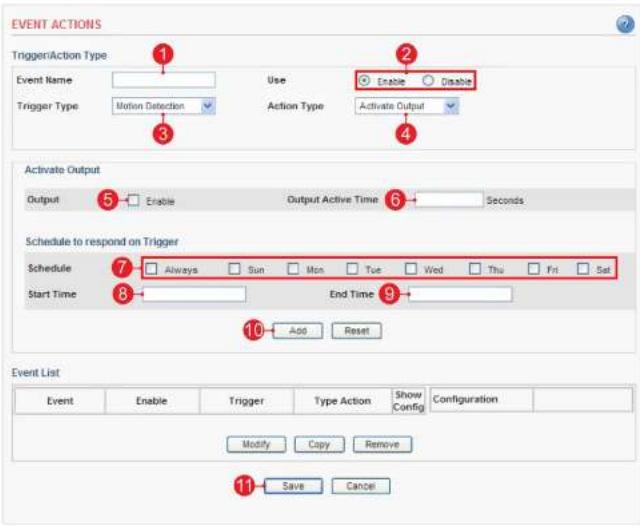
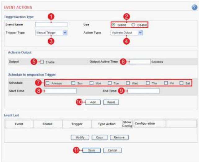
Action configuration for [Motion Detection + Activate output]
text_image
EVENT ACTIONS Trigger/Action Type Event Name Use Enable Disable Trigger Type Motion Detection Action Type Activate Output 3 4 Activate Output Output Enable Output Active Time Seconds 5 6 Schedule to respond on Trigger Schedule Always Sun Mon Tue Wed Thu Fri Sat Start Time End Time 8 10 Add Reset Event List Event Enable Trigger Type Action Show Configuration Modify Copy Remove 11 Save Cancel- Enter a descriptive event name.
- Select "enable".
- Set the trigger type to motion detection.
- Set the action type to activate output.
- Check "enable".
- Enter the output active time.
- Select the schedule by the day of the week.
- Enter the start time in a 24-hour format
Network Dome Camera User's Manual
Configuring the Network Camera
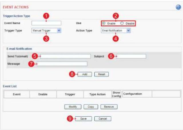
Action configuration for [Motion Detection + E-mail Notification]

text_image
EVENT ACTIONS Trigger/Action Type Event Name Trigger Type Use Motion Detection Action Type Enable Enable Email Notification E-mail Notification Send To(email) Message Subject 6 7 8 Add Reset Event List Event Enable Trigger Type Action Show Config Configuration Modify Copy Remove Save Cancel- Enter a descriptive event name.
- Select "enable".
- Set the trigger type to motion detection.
- Set the action type to e-mail notification.
- Enter the e-mail address that will receive the notification.
- Enter a descriptive subject
- Enter a descriptive message.
- Click the Add button to add configuration on the event list
Network Dome Camera User's Manual
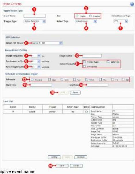
Configuring the Network Camera
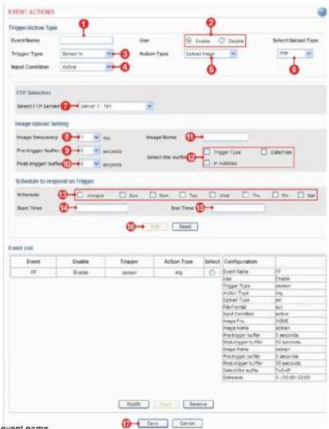
Action configuration for [Sensor Input + Upload Image + FTP]
text_image
EVENT ACTIONS TriggerAction Type Event Name Trigger Type: Sensor In Input Condition: Active Use Action Type Enable Disable Unload Image Select Upload Type FTP FTP Selection Select FTP Server 1: 1st Image Upload Setting Image frequency Pre-trigger buffer Post-trigger buffer Image Name 9 seconds 9 seconds Select the suffix Trigger Type Date/Time IP Address Schedule to respond on Trigger Schedule: Average Size Size Type Width Tens Frs Set Start Time End Time 13 14 15 16 Reset Event List Event Enable Trigger Action Type Select Configuration FF Enable sensor img Event Name FF Use Enable Trigger Type sensor Action Type img Spread Type idl File Format idl Input Control anchor Image Fts. Void Image Name admin Pre-trigger buffer 3 seconds Read Trigger buffer 10 seconds Image Name admin Pre-Trigger buffer 2 seconds Read Trigger buffer 10 seconds Select the suffix T=0-F Schedule: A / 00:00-23:69 Apply Focus Remove Event name. Save Cancel- Enter a descriptive event name.
- Select "enable".
- Set the trigger type to sensor in.
- Select the input condition
A. Active - Event will trigger when the input condition is active.
B. Inactive – Event will trigger when the input condition is inactive.
C. Change – Event will trigger when input condition is changed.
Network Dome Camera User's Manual
Configuring the Network Camera
Action configuration for [Sensor Input + Upload Image + E-mail]

text_image
EVENT ACTIONS Trigger Action Type Event Name Trigger Type Sensor 1 Action Type User Intrate Activate Select Symbol Type Input Condition Active Select Symbol Type Select User ID E-Label: Selection Send To (R-mail) Message Subject Images per stream Image Upload Setting Trigger Frequency Type Image Range Pre-Trigger Input seconds Select the output Trigger True Description Post-Trigger Buffer seconds IP-Action Schedule is required on Trigger Schedule Always Set Item Type Used Play Put Set Meet Time Last Time Reset Event Lost Event Enable Trigger Action Type Select Configuration PT Zuzhou author ing Event Name Help Use Enable Trigger True Transfer Action Type Ping Marker Type Set For Pattern Set Input Connection Action Image Pro MSME Trigger True Select Pre-Trigger Buffer Seconds Post-Trigger Buffer Seconds Dset the output "C=O" Settings "A=0.0002543" Modify Cancel Next Cancel- Enter a descriptive event name.
- Select "enable".
- Set the trigger type to sensor in.
-
Select the input condition
A. Active – Event will trigger when input condition is active.
B. Inactive – Event will trigger when input condition is inactive.
C. Change – Event will trigger when input -
Select the image frequency. (frame per second)
- Select the pre-trigger buffer.
- Select the post-trigger buffer
- Enter a descriptive image name.
- Select the suffix for the image name.
- Select the schedule by the day of the week.
- Enter the start time in a 24hour format
- Enter the end time in a 24hour format.
- Click the Add button to add configuration
Network Dome Camera User's Manual
Configuring the Network Camera
Action configuration for [Sensor Input + Activate Output]

text_image
EVENT ACTIONS Trigger/Action Type Event Name Sensor in Use Enable Disable Trigger Type Active Action Type Activate Output Input Condition 4 5 Activate Output Output Enable Output Active Time Seconds Schedule to respond on Trigger Schedule Always Sun Mon Tue Wed Thu Fri Sat Start Time End Time 9 10 Add Reset Event List Event Enable Trigger Type Action Show Configuration Modify Copy Remove Save Cancel- Enter a descriptive event name.
- Select "enable
- Set the trigger type to sensor in.
- Select the input condition
A. Active - Event will trigger when input condition is active.
B. Inactive – Event will trigger when input condition is inactive.
C. Change – Event will trigger when input condition is changed.
5. Set the action type to activate output.
C. 05-145-2021
Network Dome Camera Users Manual
Configuring the Network Camera
Action configuration for [Sensor Input + E-mail Notification]

text_image
EVENT ACTIONS Trigger/Action Type Event Name Trigger Type Input Condition 1 2 3 4 Use Enable Disable Action Type Email Notification 5 E-mail Notification Send To(mmalt) Message 6 Subject 7 8 9 Add Reset Event List Event Enable Trigger Type Action Show Configuration Modify Copy Remove 10 Save Cancel- Enter a descriptive event name.
- Select "enable
- Set the trigger type to sensor in.
- Select the input condition
A. Active - Event will trigger when input condition is active.
B. Inactive – Event will trigger when input condition is inactive.
C. Change – Event will trigger when input condition is changed.
5. Set the action type to e-mail notification.
6. Follow the email address that will receive the publication
Configuring the Network Camera
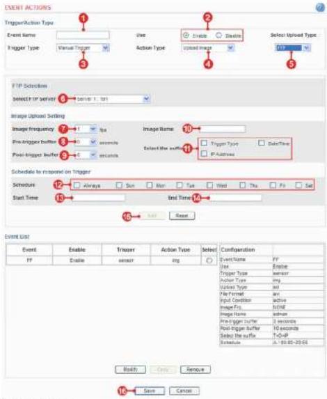
Action configuration for [Manual Trigger + Upload Image + FTP]
text_image
EVENT ACTIONS TriggerAction Type Event Name Trigger Type Virtual Trigger Use Action Type Enable Disable Update Image Select Upload Type: FTP FTP Selection SELECT FTP Server 8: Save 1: 101 Image Upload Setting Image Frequency Pre-trigger buffer 5 seconds Post-Trigger buffer 5 seconds Image Name Select the surf: Trigger Type Date/Time IP-Address Schedule to reeseed on Trigger Schedule Always Sun Mon Tax Wed Thu Fri Set Start Time End Time 12 13 14 15 Add Reset Event List Event Enable Trigger Action Type Select Configuration FF Enable sensor img Event Name FF Use Enable Trigger Type sensor Color Type ring Unlabeled Type and File Format and Input Condition active Image From Inclrl Image Name sensor Pre-trigger buffer 3 seconds Post-Trigger buffer 10 seconds Select the surf: Schedule A: 90.00-20.00 Back Save Cancel- Enter a descriptive event name.
- Select "enable"
- Select the trigger type to manual trigger.
- Set the action type to upload
- Set the upload type to FTP.
- Set the FTP server that receives uploaded image files.
- Select the image frequency. (frame per second)
2.5.1.11 1.7.1.2
Network Dome Camera Users Manual
Configuring the Network Camera
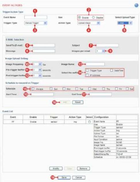
Action configuration for [Manual Trigger + Upload Image + E-mail]
text_image
EVENT ACTIONS Trigger/Action Type Event Name Trigger Type Use Action Type Enable Disable Upload image Select Upload Type Email E-MAIL Selection SendTo (E-mail) Message Subject Images per asset 1 Image Upload Style Image frequency Pre-trigger buffer Post-trigger buffer Time seconds Image Name Select the buffer Trigger Type DataTime IP Address Schedule to record on Trigger Schedule Start Time Always Sun Mon Tue Wed Thu Fri Sat End Time Start Time Reset Event List Event Enable Trigger Action Type Select Configuration PT Enable sensor img Event Name PT Use Enable Trigger Type sensor Action Type img Upload Type Set File Former Size Input Condition Active Image From: NONE Image Name Author Pre-Trigger buffer: 2 seconds Post-Trigger buffer: 15 seconds Select the buffer: T=Q=P Schedule: A1/0000-025R Modify... Save... Remove... 10 Save Cancel- Enter a descriptive event name.
- Select "enable".
-
Set the trigger type to manual trigger
-
Select pre-trigger buffer.
- Select post-trigger buffer.
- Enter a descriptive image name
Network Dome Camera User's Manual
Configuring the Network Camera
Action configuration for [Manual Trigger + Activate Output]
text_image
EVENT ACTIONS Trigger/Action Type Event Name Trigger Type Manual Trigger Use Action Type Enable Disable Activate Output Output Enable Output Active Time Seconds Schedule to respond on Trigger Schedule Start Time Always Sun Mon Tue Wed Thu Fri Sat End Time Add Reset Event List Event Enable Trigger Type Action Show/ Config Configuration Modify Copy Remove Save Cancel- Enter a descriptive event name.
- Select "enable"
- Set the trigger type to manual trigger.
- Set the action type to activate output.
- Check "enable".
Networks Dome Camera Users Manual
Configuring the Network Camera
Action configuration for [Manual Trigger + E-mail Notification]
text_image
EVENT ACTIONS Trigger/Action Type Event Name Trigger Type Manual Trigger Use Action Type Enable Disable Email Notification E-mail Notification Send To(email) Message Subject Add Reset Event List Event Enable Trigger Type Action Show Configur Configuration Modify Copy Remove Save Cancel- Enter a descriptive event name.
- Select "enable"
- Set the trigger type to manual trigger.
- Set the action type to e-mail notification.
- Enter the e-mail address that will receive the notification.
- Enter a descriptive subject.
- Enter a descriptive message.
- Click the Add button to add configuration on the event list.
- Click the Save button to save configuration.
Network Dome Camera User's Manual
Configuring the Network Camera
Action configuration for [Network Fall + Activate Output]

text_image
EVENT ACTIONS Trigger Action Type Event Name 1 Use 2 Enable Disable Trigger Type 3 Network Fail Action Type Activate Output 4 Activate Output Output Enable Output Active Time 6 Seconds (1.255) Schedule to respond on Trigger Schedule 7 Always Sun Mon Tue Wed Thu Fri Sat Start Time 8 End Time 9 10 Add Reset Event List Event Enable Trigger Action Type Select Modify Copy Remove 11 Save Cancel- Enter a descriptive event name.
- Select "enable"
- Set the trigger type to network fail.
- Set the action type to activate output.
- Check "enable"
- Enter the output active time.
- Select the schedule by the day of the week.
- Enter the start time in a 24hour format
Network Dome Camera User's Manual
Configuring the Network Camera
Action configuration for [Reboot]

text_image
EVENT ACTIONS Trigger/Action Type Event Name Trigger Type Reboot Use Action Type Enable Disable Email Notification E-mail Notification Send To(email) Message Subject Add Reset Event List Event Enable Trigger Type Action Show/Config Configuration Modify Copy Remove Save Cancel- Enter a descriptive event name.
- Select "enable".
- Set the trigger type to reboot.
Note: Action type is pre-selected to e-mail notification. - Enter the e-mail address that will receive the notification.
- Enter a descriptive subject.
- Enter a descriptive message.
- Click the Add button to add configuration on the event list.
Networks Dome Camera Users Manual
Configuring the Network Camera
Advanced > Motion Settings
text_image
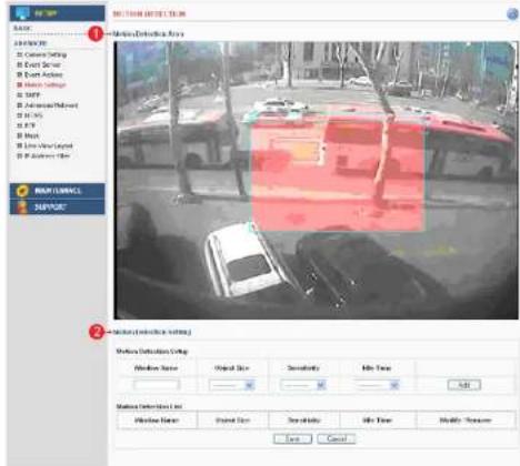
RUTTER Detection System 1 Detection Detection System 2 Detection Detection System Window Status: Optical Size: Deserately Min Time: Add Window Detection System Window Status: Optical Size: Deep Shadow Min Time: Modify Response OK Cancel1. Motion Detection Area
A. This screen displays the live video image and users can configure the motion detection field as desired on the screen.
2. Motion Detection Setting
A. Motion Detection Setup – Creates Motion Detection field. Enter the name of the Motion Detection field, Object Size, Sensitivity and Idle Time. Click the add button to create the new field. B. Motion Detection List – Displays all of the Motion Detection fields. Click the modify button to modify setting values. Click the remove button to erase the Motion Detection field.
Note: A total of 5 motion fields can be configured.
Configuring the Network Camera
Configuration of motion detection
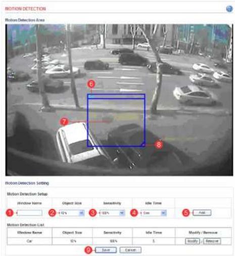
text_image
Motion Detection Motion Detection Area Motion Detection Setting Window Name Object Size Sensitivity Idle Time 1 2 3 4 5 Add Motion Detection List Window Name Object Size Sensitivity Idle Time Modify / Remove Car 0% 98% 5 Modify Remove 3 Save Cancel-
Enter a descriptive window name.
-
Select the Object Size.
Note: Higher level – Only very large objects trigger motion detection.
Lower level – Even small objects trigger motion detection.
(Recommended values: 10 - 20%)
- Select Sensitivity.
Note: Higher level – Ordinary colored objects on ordinary backgrounds will trigger the motion detection.
Lower level – Only very bright objects on a dark background will trigger the motion detection.
(Recommended values: 40 - 50%)
Network Dome Camera User's Manual
Configuring the Network Camera
Advanced > SMTP
This section describes how to configure the SMTP server.
text_image
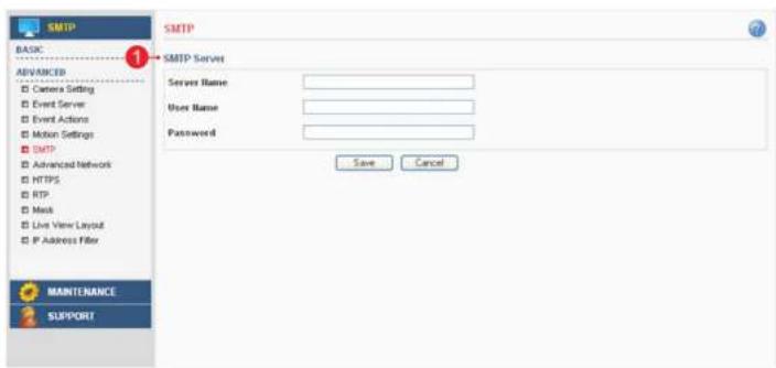
SMTP BASIC ADVANCED Camera Setting Event Server Event Actions Motion Settings SMTP Advanced Network HTTPS RTP Mask Live View Layout IP Address Filter MANTENANCE SUPPORT SMTP Server Server Name: User Name: Password: Save Cancel1. SMTP Server
A. Server Name – Enter the SMTP server's Network address or host name.
Important: A DNS server must be specified in the Setup>Advanced>Advanced network if you are using a host name.
B. User Name – Enter the user account which is registered with the SMTP server.
C. Password – Enter the user password.
Note: If your mail server does not require authentication, you don't need to enter the user name and password.
Networks Dome Camera Users Manual
Configuring the Network Camera
Advanced > Advanced Network
This section describes the advanced network settings.
text_image
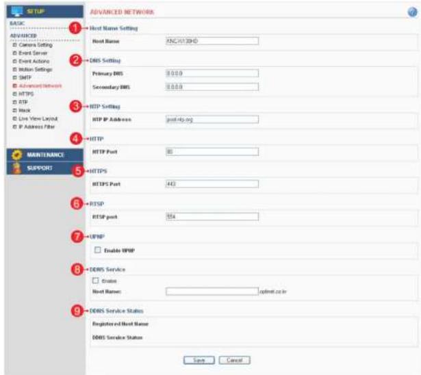
BASIC ADVANCED 1 Host Name Setting 2 DNS Setting 3 HTTP Setting 4 HTTP IP Address: post-RP.org 5 HTTP Port 80 6 HTTPS 7 HTTPS Port 440 8 RTSP 9 RTSP port 154 10 UPWP 11 Enable UPWP 12 DDRS Service 13 Create 14 Host Name: optnet.cc.in 15 DDRS Service Status 16 Registered Host Name 17 DDRS Service Status Save Cancel1. Host Name Setting
A.Host Name – The Network Camera can be accessed using a host name instead of an IP address.
The host name is usually the same as the assigned DNS name. It is always the first part of a fully qualified domain name and is always one word, with no period.
2. DNS Setting
A. Primary DNS - Enter the IP address of the primary DNS server. This server provides the translation of
Configuring the Network Camera
3. NTP Setting
A. NTP IP Address – Enter the NTP server's IP address or host name. Important: The DNS server must be specified if you are using a host name.
4. HTTP
A. HTTP Port – Enter the HTTP port the Network Camera will use. The default port is 80. Alternatively, any port in the range 1024-65535 may be used, but check first with your system administrator before changing the default setting.
5. HTTPS
A. HTTPS Port – Enter the HTTPS port the Network Camera will use. The default port is 443. Alternatively, any port in the range 1024-65535 may be used, but check first with your system administrator before changing the default setting.
6. RTSP
A. RTSP Port – Enter the RTSP port number the Network Camera will use. The default port is 554.
7. DDNS Service
A. Enable – Check this box to enable DDNS service. B. Host Name – Enter the host name which you want to use for DDNS service.
8. UPNP
A. Enable UPNP - Check this box to enable UPNP.
9. DDNS Service Status
A. Displays the DDNS service's status in your ip product.
Configuring the Network Camera
Advanced > HTTPS
This section describes the HTTPS settings. HTTPS provides encryption and secure identification of the server over an insecure network.
text_image
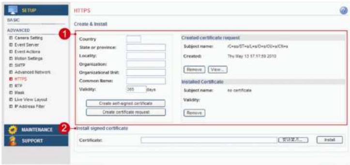
BASIC ADVANCED Camera Setting Event Server Event Actions Motion Settings SMTP Advanced Network HTTPS RTP Mask Live View Layout IP Address Filter 1 2 MANTENANCE SUPPORT HTTPS Create & Install Country: State or province: Locality: Organization: Organizational unit: Common Name: Validity: 305 days Create self-signed certificate Create certificate request Created certificate request Subject name: iC=xxiST+xL=xxiD=xxiO=xxiCB=xx Created: Try May 13 17.17.59 2010 Remove View... Installed Certificate Subject name: no certificate Validity: Remove Install signed certificate Certificate: 退出方可... Install1. Create
A. Country – Enter a 2 letter code name of the country where the certificate will be used.
B. State or province – Enter the name of the local administrative region where the certificate will be used.
C. Locality – Enter any other geographical information of the place where the certificate will be used.
D. Organization – Enter the name of the organization to which the entity identified in the 'Common Name' belongs.
E. Organizational Unit – Enter the name of the organizational unit or a department to which the entity identified in the 'Common Name' belongs.
F. Common Name – Enter the name of a person or an entity that the certificate identifies with.
G. Validity – Enter the number of days for which the certificate is valid, used in the case of self-signed certificate only.
H. Create self-signed certificate – Clicking this button after filling all the above details creates a self-signed certificate.
I. Create certificate request – Clicking this button after filling all the above details except for Validity(validity is used only for a self signed certificate) creates a certificate request which is in the form of PEM formatted data
Configuring the Network Camera
Advanced > RTP
This section describes the RTP settings. The RTP settings manage the IP addresses and port numbers to use for video streams.

text_image
SETUP BASIC Network Users Video & Audio Date & Time ADVANCED Camera Setting Event Server Event Actions Motion Settings SMTP Advanced Network HTTPS RTP Mock Live View Layout IP Address Filter MANTENANCE SUPPORT 1 2 3 4 5 6 7 8 9 10 11 12 13 14 15 16 17 18 19 20 21 22 23 24 25 26 27 28 29 30 31 32 33 34 35 36 37 38 39 40 41 42 43 44 45 46 47 48 49 50 51 52 53 54 55 56 57 58 59 60 61 62 63 64 65 66 67 68 69 70 71 72 73 74 75 76 77 78 79 80 81 82 83 84 85 86 87 88 89 90 91 92 93 94 95 96 97 98 99 100 Port Range Start Port 6970 [1024.65526] End Port 62535 [1026.65526] Multi-Net IP Address 224 10 10 10 10 10 10 10 10 10 10 10 10 10 10 10 10 10 10 10 10 10 10 10 10 10 10 10 10 10 10 10 10 10 101. Port Range
A. The RTP port range defines the range of ports that the video streams will automatically use. Limit the range of ports permitted for RTP unicast or multicast by entering the Start port and End port in the provided fields with the value between 1024 and 65535.
2. Multicast
A. IP Address – Enter the IP address that the Network Camera will use for multicast. Multicast IP address has to be specified in the range 224.xxx.xxx.xxx-239.xxx.xxx.xxx.
B. Port – Enter the multicast port the Network Camera will use for multicast. The multicast port can be adjusted in the range 1024-65534 but it has to be even values. If the multicast port is 0, the Network Camera will assign the multicast port automatically.
C. Time to Live – If IP packets (i.e. data) fail to get delivered to their destination within a reasonable length of time (which could be for various reasons), this setting will tell network routers when to discard the packet. The value is usually measured in 'hops', i.e. the number of network routers that can be passed before the packet arrives at its destination or drops in the middle.
Configuring the Network Camera
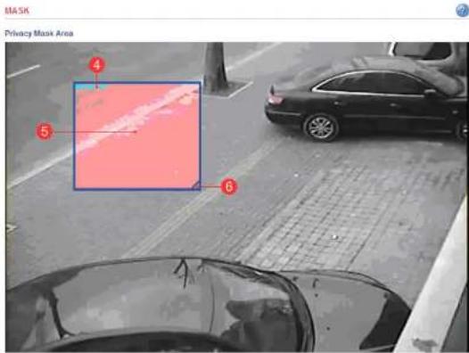
Advanced > Mask
This section describes how to configure privacy mask.
text_image
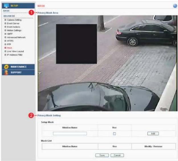
MUSTUP BASIC ADVANCED Camera Setting Event Server Event Actions Notes Settings SMTP Advanced Network HTTPS RTP Haul Line View Layout P Address Filter MAINTENANCE SUPPORT MASK 1 Privacy Mesh Area 2 Privacy Mesh Setting Setup Mask Window Name Use Add Mash List Window Name Use Modify Remove Save Cancel1. Privacy Mask Area
A. This screen displays the live video image and the user can configure a Privacy Mask window as desired on the screen.
2. Privacy Mask Setting
Configuring the Network Camera
Configuration of privacy mask
Create a Privacy Mask window with the following steps as shown below.
text_image
MASK Privacy Mask Area 4 5 6
text_image
Privacy Mask Setting Setup Mask Window Name Use Modify / Remove ① ② ③ Add Mask List Window Name Use Modify / Remove User_01 Y Modify Remove ⑦ Save Cancel- Enter a descriptive window name.
- Check the check box for "use".
- Click the "add" button to create the new Driveny Mock window
Network Dome Camera User's Manual
Configuring the Network Camera
Advanced > Live View Layout
This section describes the settings of the live view layout.

text_image
SETUP BASIC ADVANCED □ Camera Setting □ Event Server □ Event Actions □ Motion Settings □ SMTP □ Advanced Network □ HTTPS □ RTP □ Mask □ Live View Layout □ P-Address Filter LIVE VIEW LAYOUT 1 Display Control in the Live view □ Display Mic and Speaker button □ Display Snapshot button and Recording button □ Display Manual Trigger button □ Display Manual Output button Pulse Time: 1 seconds 2 User Defined Web Links □ Display Custom Link1 Name: □ Display Custom Link2 Name: □ Display Custom Link3 Name: □ Display Custom Link4 Name: □ Display Custom Link5 Name: URL http:// URL http:// URL http:// URL http:// URL http:// URL http:// Save Cancel1. Display Control In the Live View
- The live view page can be customized as desired. To enable the control buttons, check the preferred check box.
- In case of Manual alarm button, users can select pulse or active/inactive mode.
2. User Defined Web Links
- Displays the web link specified by the user in the live view page.
Network Dome Camera User's Manual
Configuring the Network Camera
Advanced > IP Address Filter
This section describes how to deny access to the Network Camera from a specific IP address.

text_image
BASIC ADVANCED Camera Setting Event Server Event Actions Motion Settings SMTP Advanced Network HTTPS RTP Mask Live View Layout IP Address Filter IP ADDRESS FILTER 1 Security Function Enable IP address filter Deny Allow 2 IP Filter Add IP Filter Starting IP Address Ending IP Address IP Filter List Starting IP Address Ending IP Address Modify / Remove Save Cancel MAINTENANCE SUPPORT1. Security Function: Deny
A. Enable IP address filter – Checking this option will allow the user to either deny or allow access to the ip address in the list, which can be controlled by clicking on Deny or Allow option.
2. IP Filter
A. Add IP Filter – Enter the IP address that you want to reject. The IP address can be entered by range. B. IP Filter List – Displays all of the denied IP addresses. Click the modify button to modify setting values. Click the remove button to erase an IP address.
Network Dome Camera User's Manual
Configuring the Network Camera
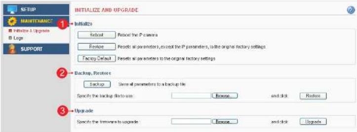
Maintenance > Initialize & Upgrade
This section describes how to reset the Network Camera and upgrade the firmware.
text_image
INITIALIZE AND UPGRADE 1 Initialize 2 Backup, Restore 3 Upgrade Initialize Reload Reload the P camera Restore Reset all parameters, except the P parameters, to the original factory settings Factory Default Reset all parameters to the original factory settings Backup, Restore Backup Save all parameters to a backup file Specify the backup file to use: Browse... and click Restore Specify the installments to upgrade: Browse... and click Upgrade1. Initialize
A. Reboot – Reboot the Network Camera.
B. Restore - Reset all setting values, except network setting values.
C. Factory Default - Reset all setting values to the original factory settings.
Important: The Default button should be used with caution. Pressing this will return all settings to the factory
default values, which also means that the IP address will need to be set again to make the unit accessible.
2. Backup, Restore
A. Backup - Click the backup button to make a backup of all of the setting values in the Network Camera.
B. Restore – If it is necessary to restore the camera to previous backed up settings, click the browse button to locate the saved backup file and then click the restore button.
3. Upgrade
Upgrade – To upgrade the firmware for the Network Camera, click the browse button to find the firmware file and then click the upgrade button.
Network Dome Camera User's Manual
Configuring the Network Camera
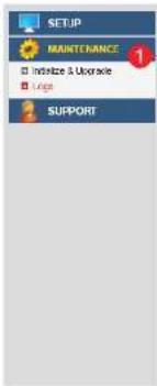
Maintenance > Logs
This section describes the system logs.
text_image
SETUP MAINTENANCE □ Initialize & Upgrade □ Lungs SUPPORT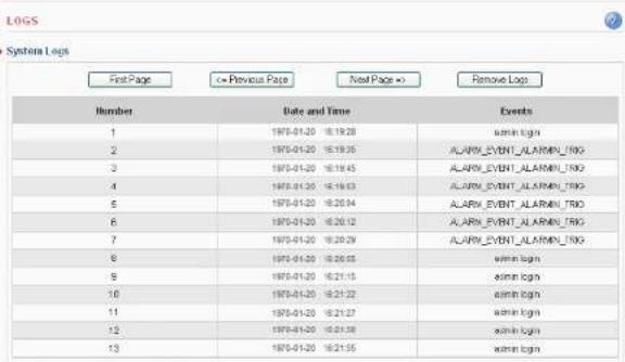
text_image
LOGS System Logs First Page <= Previous Page Next Page >> Remove Logs Number Date and Time Events 1 1975-01-20 16:19:28 win login 2 1975-01-20 16:19:35 ALARM_EVENT_ALARMEN_TRIG 3 1975-01-20 16:19:45 ALARM_EVENT_ALARMEN_TRIG 4 1975-01-20 16:19:53 ALARM_EVENT_ALARMEN_TRIG 5 1975-01-20 16:20:04 ALARM_EVENT_ALARMEN_TRIG 6 1975-01-20 16:20:12 ALARM_EVENT_ALARMEN_TRIG 7 1975-01-20 16:20:29 ALARM_EVENT_ALARMEN_TRIG 8 1975-01-20 16:20:55 win login 9 1975-01-20 16:21:15 win login 10 1975-01-20 16:21:22 win login 11 1975-01-20 16:21:27 win login 12 1975-01-20 16:21:38 win login 13 1975-01-20 16:21:55 win login1. System Logs
The Network Camera records when a particular event occurs in the log record.
A. First Page – Go to the first page of the log record.
B. Previous Page – Go to the previous page of the log record.
C. Next Page - Go to the next page of the log record
Network Dome Camera User's Manual
Configuring the Network Camera
Support > System / Help
This section describes the system information and help menu.
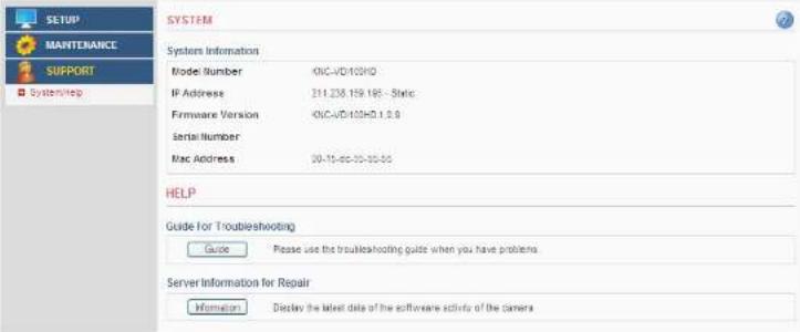
text_image
SETUP MANTENANCE SUPPORT SystemsHelp SYSTEM System Information Model Number KNC-VD/100HD IP Address 211.236.159.168 - Static Firmware Version KNC-VD/100HD 1.0.0 Serial Number Mac Address 00-10-00-00-00-00 HELP Guide for Troubleshooting Guide Please use the Troubleshooting guide when you have problems Server Information for Repair Information Display the latest date of the software activity of the camera1. System Information
Displays the system information of the Network Camera.
2. Guide for Troubleshooting
If you suspect a problem is being caused by incorrect configuration or some other minor problem,
consult the troubleshooting guide.
3. Server Information for Repair
It would be helpful to have this report when you contact your support channel.
Network Dome Camera User's Manual
Product Specifications
| ITEM DESCRIPTION | NOTE | ||
| Image Device 1/3" SONY 2.1M Progressive Scan CMOS | |||
| Lens F=3.7mm / F2.5 | Board Lens Unit: mm | ||
| Day and Night True Day & Night with ICR Mechanism | |||
| Minimum Illumination | Standard type: 0.1 lux at 30 IRE, F1.4LED type: 0 lux at 30 IRE, F1.4 | ||
| IR LED 15ea | |||
| Video | Video Codec | H.264 Main ProfileMotion JPEG | |
| Resolutions(H.264/MJPEG) | H.264 : MAX 1920x1080 + Analog Output @ 30fpsMJPEG : MAX 1280x720 @30fps | ||
| Video Streaming | Simultaneous Motion JPEG and H.264Controllable frame rate and bandwidthConstant and variable bit rate (H.264) | ||
| Image Settings | Brightness, Contrast, Saturation, Sharpness, WhiteBalance, Exposure Control, Back Light CompensationCompression levels : 100 (Motion JPEG)Viewer Magnification : 0.5x, 1x, 1.5x, 2xOverlay capabilities : time, date, text, privacy mask | ||
| Network | Security | Multiple user access levels with password protectionIP address filtering: Deny, Allow | |
| Supported Protocols | IPv4, HTTP, HTTPS, TCP, RTSP, RTP, UDP, IGMP,RTCP, SMTP, FTP, ICMP, DHCP, ARP, DNS, DDNS,UPnP | ||
| System Integration | API | Onvif 1.0Open API for software integration, including API, SDK | |
| Intelligent Video Video motion detection | |||
| Alarm Triggers | Intelligent video, external inputs, manual triggers,Network Fail, Reboot, Schedule | ||
| Alarm Events File upload via FTP, e-mail; Notification via e-mail | |||
Network Dome Camera User's Manual
Product Specifications
| ITEM DESCRIPTION | NOTE | ||
| Web Viewer | Video format changeStream play / stopSnapshotInstant recording(Max 5. minutes)Manual triggerOutput controlScreen magnificationStatus indicator (video, record, alarm, motion) | ||
| General | Enclosure Plastic case | ||
| Processors and Memory | CPU : ARM 926EJ-SRAM : 128 MBFlash : 64 MBReal-time clock with backup battery | ||
| Power | LED type: DC12V( ± 10%), Max. 320mAStandard Type: DC12V( ± 10%), Max. 210mAPower over Ethernet Class 3 (IEEE 802.3af) | ||
| Interfaces | RJ-45 for Ethernet 10baseT/100baseTX with PoE3.5mm Power Input: DC 12Vconnector for Service Video | ||
| Operating Conditions | Temperature: - 10°C ~ +50°C (14°F ~ 122")Humidity 20-80% RH (non-condensing) | ||
| Dimension 120(O) x 55(mm) Unit: mm | |||
| Weight 350g | |||
| Accessories | Installation Guide, CD with installation and management tools, CMS software, installation guide and User's guideVisit the KT&C Support Web to get the latest KCMS-3000 (Free central management software) at www.ktncusa.com | ||
Troubleshooting
This section describes the symptoms, possible causes and corrective actions.
| Symptoms Remedial Actions Reference | |||
| Problems with IP address setting | The Network Camera is located on a different subnet. | If the Network Camera and your computer are located on different subnets, you will not be able to set the IP address. Contact your network administrator for obtaining an IP address on the same subnet as the computer that you are performing installation from. | |
| The IP address is being used by another device. | Contact your network administrator. You must obtain a new IP address and reinstall the Network Camera. | ||
| The Network Camera cannot be accessed from a web browser. | Cannot log in | Check if the user ID and password is correct. The ID and password are case sensitive. | |
| IP address has been changed by DHCP | Reconfigure the IP address using the IP Installer. If a dynamic IP address via DHCP is required, enable the DHCP and configure the SMTP Notification (Email) For IP Address Change from the Setup>Basic>Network settings. | Installation Guide | |
| Other networking problems | Check the network cable by connecting it to another network device, then Ping the device from your computer. | ||
| The Network Camera cannot be accessed externally | Firewall protection | Check the Internet firewall with your network administrator. | |
| Default gateway required | Check if you need to configure the default gateway settings. | 13p | |
| The Network Camera does not turn on | DC power supply | Check the power. | |
| PoE power supply | Check the Ethernet (CAT 5) cable that is connected to a PoE compatible power supply unit. Some power supply unit may not provide power when the total power supply limitation is exceeded. Check the Operating Instructions of the PoE power supply unit for maximum power output. | ||
| No image displayed in the web viewer | ActiveX | To run the View Program in Microsoft Internet Explorer, configure your Web browser to allow the ActiveX controls. Also, make sure that Web Viewer component is installed on your PC. | 9p |
| Missing images in uploads | This can occur when trying to use a larger image buffer than is actually available. Try lowering the frame rate or the upload period. | ||
| Slow performance | Slow performance may be caused by e.g. heavy network traffic, multiple users accessing the Network Camera, low performance computer, using features such as Motion Detection, Event action. | ||
Glossary
This section provides glossary for understanding the Network Camera.
A.
ActiveX: A control (or set of rules) used by a browser. ActiveX controls are often downloaded and installed automatically as required.
API: Application Programming Interface. The API can be used for integrating products into other applications.
ARP: Address Resolution Protocol. Used to associate an IP address to a hardware MAC address. A request is broadcasted on the local network to find out what the MAC address is for the IP address.
Aspect ratio: A ratio of width to height in images. A common aspect ratio used for television screens and computer monitors is 4:3. High-definition television (HDTV) uses an aspect ratio of 16:9.
B.
BOOTP : A protocol that can automatically configure a network device (give it an IP address).
C.
CGI: Common Gateway Interface. A set of rules (or a program) that allows a Web Server to communicate with other programs.
Client/Server: Describes the network relationship between two computer programs, in which one, the client makes a service request from another - the server.
D.
DC-Irl: The iris, a mechanism that automatically regulates the amount of light allowed entering to CCD, is electrically controlled by the camera
dB (Decibels): A unit to measure sound level changes. A 3dB change is the smallest level change we can hear. A gain of 0dB will leave the signal level unchanged.
De-interlacing: De-interlacing is the process of converting a stream of interlaced frames to a stream of progressive frames.
A-DSL : Digital Subscriber Line. A means of transferring data via standard phone line.
E.
Ethernet: A widely used networking standard.
F.
Firewall: A virtual barrier between a LAN (Local Area Network) and other networks, e.g. the internet.
FTP: File Transfer Protocol. Used for the simple transfer of files to and from an FTP server.
Full-duplex: Transmission of data, e.g. audio, in two directions simultaneously.
Glossary
1.
Intranet: A private network limited to an organization or corporation. Usually closed to external traffic. IP: Internet Protocol.
IP address: A unique set of numbers used by a computer on the network to allow it to be identified and found.
J.
JPEG: A standard image format, used widely for photographs. Also known as JPG
L.
LAN: A local area network (LAN) is a group of computers and associated devices that typically share common resources within a limited geographical area.
Linux: A popular operating system that is "open source" and practically free of charge.
Lux: A standard unit for light measurement.
M.
Mbit/s: Megabits per second. A unit for measuring speeds in networks. A LAN might run at 10 or 100 Mbit/s
MPEG4: A video compression standard that makes good use of bandwidth. It can provide DVD-quality video streams at less than 1 Mbit/s.
Multicast: A bandwidth-conserving technology that reduces bandwidth usage by simultaneously delivering a single stream of information to multiple network recipients.
P.
Ping: A small utility used for sending data packets to network resources to check that they are working and that the network is intact.
Pre / post alarm image: The images from immediately before and after an alarm.
Protocol: A special set of rules governing how two entities will communicate. Protocols are found at many levels of communication, and there are hardware protocols and software protocols.
R.
Router: A device that determines the next network point to which a packet should be forwarded on its way to its final destination. A router is often included as part of a network switch.
RTP: Real Time Transfer Protocol. A transfer protocol designed for the delivery of live content, e.g. MPEG4.
RTSP: Real Time Streaming Protocol is a network control(e.g. play, stop, etc) protocol used in multimedia, and a starting point for negotiating transports such as RTP, multicast and Unicast.
Glossary
T.
TCP/IP: Transmission Control Protocol/Internet Protocol. A suite of network protocols that determine how data is transmitted. TCP/IP is used on many networks, including the Internet. TCP keeps track of the individual packets of information and IP contains the rules for how the packets are actually sent and received.
U.
UDP: The User Datagram Protocol is a communication protocol that offers a limited amount of service when messages are exchanged between computers in a network that uses the IP. UDP is an alternative to the TCP and, together with IP, is also known as UDP/IP.
Unicast: Communication between a single sender and a single receiver over a network.
URL: Uniform Resource Locator. An "address" on the network.
V.
Varifocal: A varifocal lens provides a various range of focal length, as opposed to a lens with a fixed focal length, which only provides one.
W.
WAN: Wide Area Network. Similar to a LAN, but on a larger geographical scale.
Web server: A program on a computer that delivers the resources requested by the web use