
BG-UM88-100M - Router BZBGear - Free user manual and instructions
Find the device manual for free BG-UM88-100M BZBGear in PDF.

| Product Type | 18Gbps 8x8 HDBaseT Matrix Switch with ARC |
| HDMI Compliance | HDMI 2.0b |
| HDCP Compliance | HDCP 2.2 and HDCP 1.4 |
| Video Bandwidth | 18Gbps |
| Maximum Video Resolution | 4K@60Hz 4:4:4, 4K@60Hz 4:2:2, 4K@60Hz 4:2:0 |
| Color Depth | 12-bit (4K), 16-bit (1080p) |
| HDBaseT Transmission Distance | Up to 328 ft (100 m) via single CAT 5e/6/7 cable |
| Number of Inputs | 8 x HDMI |
| Number of Outputs | 8 x HDMI, 8 x HDBaseT (mirrored), 8 x Coaxial, 8 x Stereo Audio (3.5mm) |
| ARC Function | Yes, on local HDMI and HDBaseT output ports |
| Audio Formats (HDMI pass-through) | PCM 2.0/5.1/7.1, Dolby Digital/Plus/EX, Dolby TrueHD, DTS, DTS-EX, DTS-96/24, DTS High Res, DTS-HD Master Audio, DSD |
| Coaxial Audio Formats | PCM 2.0, Dolby Digital/Plus, DTS |
| HDR Support | HDR10, HDR10+, Dolby Vision, HLG |
| IR Frequency | 20KHz ~ 60KHz |
| EDID Management | 21 predefined, 2 user-defined, and 16 copy EDID modes |
| Control Methods | Front panel, IR remote, RS-232, LAN, Web GUI |
| Power over Cable (POC) | 24V POC on all HDBaseT ports |
| Power Supply | AC 100-240V, 50/60Hz |
| Power Consumption | 128W (Max) |
| Dimensions (Matrix) | 440mm (W) x 362mm (D) x 88mm (H) |
| Dimensions (Receiver) | 163mm (W) x 90.3mm (D) x 18mm (H) |
| Weight (Matrix) | 6.9 kg |
| Weight (Receiver) | 392 g |
| Operating Temperature | 0°C ~ 40°C (32°F ~ 104°F) |
| Storage Temperature | -20°C ~ 60°C (-4°F ~ 140°F) |
| Housing Material | Metal Enclosure |
| Included Accessories | 1x Matrix, 8x Receivers, IR remote, power cable, RS-232 cable, Phoenix connectors, IR cables, mounting ears, user manual |
Frequently Asked Questions - BG-UM88-100M BZBGear
s hdmi y arc 1.s edid in x from z.s reset!. The device will reset to default settings.User questions about BG-UM88-100M BZBGear
0 question about this device. Answer the ones you know or ask your own.
Ask a new question about this device
Download the instructions for your Router in PDF format for free! Find your manual BG-UM88-100M - BZBGear and take your electronic device back in hand. On this page are published all the documents necessary for the use of your device. BG-UM88-100M by BZBGear.
USER MANUAL BG-UM88-100M BZBGear
18Gbps 8 by 8 HDBaseT (100M) Matrix with ARC Function

natural_image
Front view of a black industrial electronic device with multiple cylindrical modules and a control panel (no visible text or symbols)User Manual
Thank you for purchasing this product
For optimum performance and safety, please read these instructions carefully before connecting, operating or adjusting this product. Please keep this manual for future reference.
Surge protection device recommended
This product contains sensitive electrical components that may be damaged by electrical spikes, surges, electric shock, lighting strikes, etc. Use of surge protection systems is highly recommended in order to protect and extend the life of your equipment.
Table of Contents
- Introduction.... 1
- Features....1
- Package Contents....2
- Specifications....2
- Operation Controls and Functions....4
5.1. Matrix Panel 4
5.2.HDBaseT Receiver Panel 6 - IR Remote 7
- IR Control System....9
- IR Cable Pin Assignment....11
- EDID Management....11
- Matrix Audio and RS-232 Introduction.... 13
- Web GUI User Guide.... 14
- RS-232 Control Command.... 22
- Application Example....29
- Tech Support...... Back cover
- Warranty Back cover
- Mission Statement.... Back cover
1. Introduction
The BG-UM88-100M-KIT is an 18Gbps 8 by 8 HDBaseT(100M) matrix switch that can connect 8 HDMI sources to 16 displays. Each HDMI output can be mirrored to allow a simultaneous output using a CAT cable. Resolution is up to 4K@60Hz4:4:4. The HDBaseT output's transmission distance is up to 328ft / 100m over a single CAT 5e/6/7 cable.
The device supports IR matrix and Audio matrix functionality. The ARC function allows the HDMI or HDBaseT display device's audio signal to be returned to or extracted from the coaxial and analog audio outputs using the Web GUI or ASCII code control. The IR and RS-232 signal transmission is bi-directional. For example, the IR signal will transmit from port 1 of the matrix to the HDBaseT receiver connected to output port 1. The BG-UM88-100M-KIT can be controlled via the front panel buttons, IR remote, RS-232, LAN, and Web GUI
2. Features
☆ HDMI 2.0b, HDCP 2.2 and HDCP 1.4 compliant
☆ 8 HDMI inputs, 8 HDMI outputs and 8 HDBaseT mirrored outputs
※ Resolution up to 4K@60Hz 4:4:4
☆ HDMI ports transmit 18Gbps lossless uncompressed video bandwidth
18Gbps lossless compressed HDBaseT signal transmission
☆ 4K->1080P Down Scaler
☆ Dolby Vision, HDR10+, HLG are supported
HDBaseT output can extend video transmission distance up to 328ft / 100 meters via a single CAT 5e/6/7 cable.
☆ HDMI audio pass-through up to 7.1CH HD audio (LPCM, Dolby TrueHD and DTS-HD Master Audio)
☆ ARC function on local HDMI and HDBaseT output ports
☆ IR matrix and Audio matrix are supported
☆ Smart EDID management
☆ 24V POC on all HDBaseT ports
☆ Control via front panel buttons, IR remote, RS-232, LAN, and Web GUI
3. Package Contents
① 1x 8 by 8 HDMI and HDBaseT Matrix Switch
② 8x HDBaseT Receiver
③ 1x Matrix IR Remote
④ 1x 100\~240V AC 50/60Hz Power cable
⑤ 1x RS-232 serial cable (1.5 meters, male to female head)
⑥ 16x 3-pin Phoenix Connector
⑦ 9x IR Blaster cable (1.5 meters)
⑧ 10x 20\~60KHz IR Receiver cable (1.5 meters)
⑨ 18x Mounting Ear (Matrix and Receiver)
1x User Manual
- Specifications
| Technical | |||
| HDMI Compliance | HDMI 2.0b | ||
| HDCP Compliance | HDCP 2.2 and HDCP 1.4 | ||
| Video Bandwidth | 18Gbps | ||
| Video Resolution | Up to 4K2K@50/60Hz (4:4:4) | ||
| Color Space | RGB, YCbCr 4:4:4/4:2:2/4:2:0 | ||
| Color Depth | 12-bit (4K), 16-bit (1080P) | ||
| HDMI Audio Formats(Pass-through) | PCM2.0/5.1/7.1CH, Dolby Digital/Plus/EX, Dolby True HD,DTS, DTS-EX,DTS-96/24, DTS High Res, DTS-HD MasterAudio, DSD | ||
| Coax Audio Formats | PCM 2.0, Dolby Digital / Plus, DTS, | ||
| L/R Audio Formats | PCM2.0 | ||
| HDR formats | 4:4:4,4:2:2,4:2:0(10,12bit deep color)HDR10,HDR10+,Dolby Vision, HLG | ||
| Infrared | 20KHz ~ 60KHz | ||
| ESD Protection | Human-body Model:±8kV (Air-gap discharge), ±4kV (Contact discharge) | ||
| Connection | |||
| Matrix | |||
| 8×INPUT [HDMI Type A, 19-pin female]10×IR INPUT [3.5mm Stereo Mini-jack] | |||
| Output Ports | 8×HDMI OUTPUT [HDMI Type A, 19-pin female]8×HDBaseT port [RJ45]9×IR OUTPUT [3.5mm Stereo Mini-jack]8×RS-232 [3-pin Phoenix connector]8×SPDIF{COAX}8×Stereo Audio[3.5mm Stereo Mini-jack]1×LAN [RJ45] | ||
| Control Ports | 1×TCP/IP [RJ45]1×RS-232 [D-Sub 9] | ||
| HDBaseT Receiver | |||
| Input Ports | 1×HDBaseT IN [ RJ45]1×IR IN [3.5mm Stereo Mini-jack] | ||
| Output Ports | 1×HDMI OUT [HDMI Type A, 19-pin female]1×IR OUT [3.5mm Stereo Mini-jack] | ||
| Control Ports | 1×SERVICE [Micro USB, Update port]1×RS-232 [Phoenix jack]2×LAN [RJ45] | ||
| Mechanical | |||
| Housing | Metal Enclosure | ||
| Color | Black | ||
| Dimensions | TX: 440mm (W)×362mm (D)×88mm (H)RX: 163mm (W)×90.3mm (D)×18mm (H) | ||
| Weight | TX: 6.9 kg, RX: 392g | ||
| Power Supply | AC 100 - 240V 50/60Hz | ||
| Power Consumption | 128W (Max) | ||
| Operating Temperature | 0°C ~ 40°C / 32°F ~ 104°F | ||
| Storage Temperature | -20°C ~ 60°C / -4°F ~ 140°F | ||
| Relative Humidity | 20~90% RH (non-condensing) | ||
| Resolution / Distance | 4K60 - Feet / Meters | ||
| CAT 5e/6/7 | 328ft / 100M | ||
| Resolution / Cable length | 4K60 -Feet / Meters | 4K30 -Feet / Meters | 1080P60 -Feet / Meters |
| HDMI IN / OUT | 16ft / 5M | 32ft / 10M | 50ft / 15M |
The use of "Premium High Speed HDMI" cable is highly recommended
5. Operation Controls and Functions
5.1 Matrix Panel
Front Panel
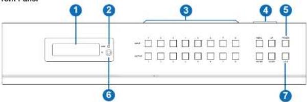
| NO. | Name | Function Description |
| 1 | OLED screen | Display matrix switching status, input / output port, EDID, Baud rate, IP Address. |
| 2 | Power LED | The LED will illuminate in green when the product is connected to power supply, and red when the product is on standby. |
| 3 | Input / Output buttons | You need to press an output button (1~8) firstly and then press an input button (1~8) to select the corresponding Input source for the output port. |
| 4 | MENU / ENTER / UP /DOWN | 1 EDID Check: On the initial OLED display screen, press "MENU" button to enter the Matrix switching state interface, then press "UP/DOWN" button to check the current EDID information of each HDMI input port.2 EDID setting: On the initial OLED display screen, press "MENU" button to enter the EDID setting interface, press "UP/DOWN" button to select the required EDID, and press the "ENTER" button. A prompt "copy to input:" will appear. Then press "UP/DOWN" button to select the input port you need to set, and press "ENTER" button again to confirm.3 Baud rate setting: On the initial OLED display screen, press "MENU" button to enter the Baud rate interface, and press "UP/DOWN" button to select the required Baud rate, finally press the "ENTER" button to confirm the setting.4 IP Address Check: On the initial OLED display screen, press "MENU" button to enter the IP interface, then press "UP/DOWN" button to check the current IP address. Pressing the "MENU" button again will return to the initial OLED display status. |
Rear Panel

| No. | Name | Function Description |
| 1 | INPUT ports(1-8) | HDMI input ports, connect to HDMI source device such as DVD or PS4 with an HDMI cable. |
| 2 | OUTPUT ports(1-8) | HDBaseT ports, connect to HDBaseT Receiver via CAT cable |
| HDMI output ports, connect to HDMI display device such as TV or monitor with an HDMI cable. | ||
| 3 | LAN | This port is connected to a router and the LAN port of the HDBaseT Receiver can connect Internet device such as PC or laptop. |
| 4 | AUDIO IN ports | L/R, optical and coaxial audio input ports, connect to external audio source device such as PC or DVD. |
| 5 | RS-232 port(1-8) | Connect to a PC or control system by 3-pin phoenix connector serial cable to transmit command between the Matrix and HDBaseT Receiver. |
| DIGITAL port(1-8) | Coaxial audio output port, connect to audio output device such as audio amplifier via a coaxial cable. | |
| STEREO port(1-8) | Stereo audio output port, connect to an amplifier or speaker via a 3.5mm audio cable. | |
| 6 | IR EXT | If the IR receiver window of the unit is blocked or the unit is installed in a closed area out of infrared line of sight, the IR receiver cable can be inserted to the "IR EXT" port to receive the IR remote signal. |
| 7 | IR INPUT ports | Connect to IR receiver cable, the IR receive signal will emit to "IR OUT" port of the corresponding HDBaseT Receiver. |
| 8 | IR OUTPUTports | Connect to IR blaster cable, the IR emit signal is from "IR IN" port of the corresponding HDBaseT Receiver. |
| 9 | TCP/IP port | This port is the link port for TCP/IP control and connect to an active Ethernet link by an RJ45 cable. |
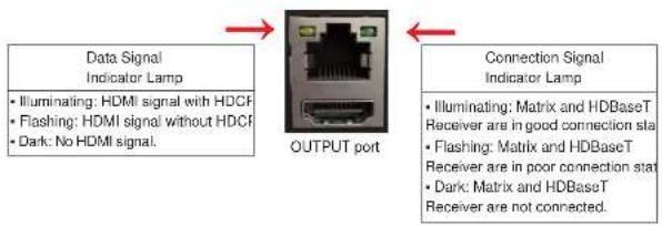
flowchart
graph LR
    A["Data Signal Indicator Lamp"] --> B["OUTPUT port"]
    C["Illuminating: HDMI signal with HDCF\nFlashing: HDMI signal without HDCF\nDark: No HDMI signal."] --> B
    D["Connection Signal Indicator Lamp"] --> E["Illuminating: Matrix and HDBaseT\nReceiver are in good connection sta\nFlashing: Matrix and HDBaseT\nReceiver are in poor connection sta\nDark: Matrix and HDBaseT\nReceiver are not connected."]
5.2 HDBaseT Receiver Panel

| No. | Name | Function Description |
| 1 | POWER LED | Power LED indicator, LED will illuminate when the device is connected with power supply. |
| 2 | SERVICER port | Firmware update port |
| 3 | DC 24V | Plug the DC 24V/1A power cord into this port and connect the adapter to AC wall outlet.Note:The Matrix supports POC function, so the Receiver doesn't need to connect power supply when HDBaseT IN port is connected to HDBaseT port of the Matrix. |
| 4 | HDBaseT IN port | Connect to HDBaseT output port of the Matrix with CAT cable. |
| 5 | Connection Signal Indicator | Illuminating: Matrix and Receiver are in good connection status.Flashing: Matrix and Receiver are in poor connection status. |
| 7 | IR IN | Connect to IR receiver cable, the IR signal will emit to corresponding IROUT port of the Matrix. |
| 8 | IR OUT | Connect to IR blaster cable, the IR signal will be received from the corresponding IR IN port of the Matrix. |
| 9 | HDMI OUT port | HDMI output port, connect to HDMI display device such as TV or monitor with HDMI cable. |
| 10 | RS-232 port | Connect to a PC or control system by 3-pin phoenix connector cable to transmit command between the Matrix and HDBas Receiver. |
| 11 | LAN ports | Connect Ethernet cables to these ports to provide a wired Ethernet connection to local devices. |
6. IR Remote
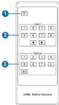
① Power on or Standby: Power on the Matrix or set it to standby mode.
② Input 1/2/3/4/5/6/7/8: Select input source button.
◀ ▶ : Select the last or next input source button.
③ Output 1/2/3/4/5/6/7/8 button: Select output source button.
All: Select all output source simultaneously. For example, when you press the "All" button and then press input "1" button, at this time the input "1" source will output to all display devices.
Operation instruction: You need to press the output button firstly and then press input button to select the corresponding input source. For example,
Press Output-X (X means output button from 1 to 8, including "All" button) Then press Input-Y
(Y means input button from 1 to 8)
The Matrix can be selected input and output source by using the IR remote. There are two ways to receive the IR remote signal.

natural_image
Front panel of a computer control interface with indicator lights and a blank display (no text or symbols)
IR remote of the Matrix
Alternate method: If the IR receiver window of the Matrix is blocked or the Matrix is installed in a closed area out of infrared line of sight, the IR receiver cable can be inserted to the "IR EXT" port to receive the IR remote signal. The furthest distance of using the IR remote is 7 meters and the IR remote is directly faced to the IR receiver head. The diagram is shown as below.

7. IR Control System
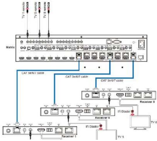
The device is not only a matrix switch but also an extender. It supports bi-directional IR control. When the matrix is connected to an HDBaseT Receiver through CAT 5e/6/7 cable, users can control remote display devices (HDBaseT) or input source devices (Matrix) through IR signal transmission. Note that the IR signal transmission method is different from Matrix (local) to HDBaseT Receiver (remote) than from HDBaseT Receiver (remote) to Matrix (local).
At the Matrix end (Local end): the IR signal is one-to-one transmission. This means the IR INPUT 1 port signal of the Matrix will emit to the IR output port of the HDBaseT Receiver 1 and the IR INPUT 2 port signal of the Matrix will emit to IR output port of the HDBaseT Receiver 2 etc. The IR signal doesn't follow the video switch. The IR INPUT ALL port signal of the Matrix will emit to all IR output ports of HDBaseT receivers simultaneously. Please see the following connection diagram.
flowchart
graph TD
    A["TV 1 remote"] --> B["Matrix"]
    C["TV 5 remote"] --> B
    D["TV 8 remote"] --> B
    B --> E["CAT 5/6/7 cable"]
    B --> F["CAT 5/6/7 cable"]
    B --> G["CAT 5/6/7 cable"]
    B --> H["Receiver 5"]
    B --> I["Receiver 5"]
    B --> J["IR Blaster"]
    B --> K["IR Blaster"]
    B --> L["TV 8"]
    M["Receiver 1"] --> N["TV 5"]
    O["IR Blaster"] --> P["TV 8"]
At HDBaseT receiver (Remote end): The IR signal follows video switch. For example,
the HDMI output signal on the HDBaseT Receiver 1 is from the HDMI INPUT 3 port, so IR input signal of the HDBaseT Receiver 1 will emit to IR OUTPUT 3 port of the Matrix. The HDMI output signal on the HDBaseT Receiver 3 is from the HDMI INPUT 6 port. Then, IR input signal of the HDBaseT Receiver 3 will emit to IR OUTPUT 6 port of the Matrix etc. Any of HDBaseT Receiver's IR IN signal can output from IR OUTPUT ALL port of the Matrix and the IR signal output of the Matrix depends on your IR remote of source device. Please see the following connection diagram.

flowchart
graph TD
    A["Matrix"] --> B["Blu-ray player"]
    A --> C["Blu-ray player remote"]
    A --> D["Receiver 1"]
    A --> E["Receiver 2"]
    A --> F["TV 1"]
    A --> G["TV 3"]
    B --> H["DVD"]
    C --> I["DVD remote"]
    D --> J["DVD remote"]
    E --> K["DVD remote"]
    F --> L["DVD remote"]
Figure 2: IR connection diagram (HDBaseT Receiver end)
8. IR Cable Pin Assignment
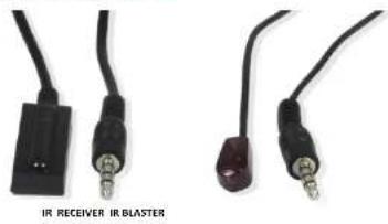
natural_image
Two black cables with connectors, one labeled 'IR RECEIVER IR BLASTER' (no other text or symbols visible)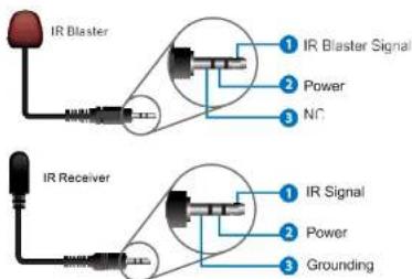
9. EDID Management
This Matrix has 21 factory defined EDID settings, 2 user-defined EDID modes and 16 copy EDID modes. You can select defined EDID mode or copy EDID mode to input port through front panel buttons, ASCII control or Web GUI.
On-panel button operation: On the initial OLED display screen, press "MENU" button to enter the EDID setting interface, press "UP/DOWN" button to select the required EDID, and press the "ENTER" button. A prompt "copy to input:" will appear. Then press "UP/DOWN" button to select the input port you need to set, and press "ENTER" button again to confirm this operation.

The defined EDID setting list of the product is shown as below:
| EDID Mode | EDID Description |
| 1 | 1080p, Stereo Audio 2.0 |
| 2 | 1080p, Dolby/DTS 5.1 |
| 3 | 1080p, HD Audio 7.1 |
| 4 | 1080i, Stereo Audio 2.0 |
| 5 | 1080i, Dolby/DTS 5.1 |
| 6 | 1080i, HD Audio 7.1 |
| 7 | 3D, Stereo Audio 2.0 |
| 8 | 3D, Dolby/DTS 5.1 |
| 9 | 3D, HD Audio 7.1 |
| 10 | 4K2K30_444, Stereo Audio 2.0 |
| 11 | 4K2K30_444, Dolby/DTS 5.1 |
| 12 | 4K2K30_444, HD Audio 7.1 |
| 13 | 4K2K60_420, Stereo Audio 2.0 |
| 14 | 4K2K60_420, Dolby/DTS 5.1 |
| 15 | 4K2K60_420, HD Audio 7.1 |
| 16 | 4K2K60_444, Stereo Audio 2.0 |
| 17 | 4K2K60_444, Dolby/DTS 5.1 |
| 18 | 4K2K60_444, HD Audio 7.1 |
| 19 | 4K2K60, Stereo 2.0 HDR |
| 20 | 4K2K60, Dolby/DTS 5.1 HDR |
10. Matrix Audio and RS-232 Introduction
The audio Matrix supports 28 channel audio inputs and 16 channel audio outputs. Audio inputs include 8 channel HDMI input audio, 8 channel HDMI output ARC audio, 8 channel HDBaseT output ARC audio, 2 channel analog audio input, 1 channel optical audio input, and 1 channel coaxial audio input; audio outputs include 8 channel coaxial/analog audio output (When the audio format is PCM, coaxial audio and analog audio are the same; when it is multi-channel audio, only the coaxial audio output is active), and 8 channel HDMI audio embedded output. You can switch audio and set audio parameters through RS-232 command and Web GUI, please refer to Web and RS-232 instructions for details.
The RS-232 channel is also one-to-one transmission. For example, the RS-232 port of the OUTPUT 1 at Matrix end follows the RS-232 port at HDBaseT Receiver 1. The RS-232 port of the OUTPUT 3 at Matrix end follows the RS-232 port at HDBaseT Receiver 3 etc. Please see the following connection diagram.
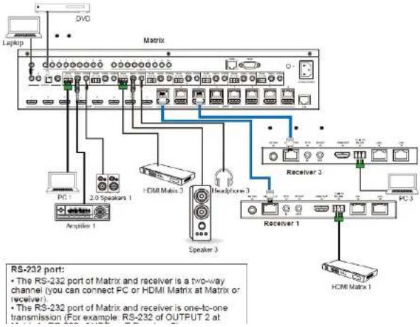

Figure 4: 3-pin phoenix connector to USB
11. Web GUI User Guide
The Matrix can be controlled by Web GUI. The operation method is shown as below:
Step 1: Obtain the current IP Address.
The default IP address is 192.168.1.100. You can obtain the current Matrix IP address in two ways:
Method 1: View the current IP address via panel buttons. On the initial OLED display, press
"MENU" button to enter the IP interface, then press "UP/DOWN" button to check the current IP address.
Method 2: You can get the IP address via RS-232 control. Send the ASCII command
"ripconfig!" through a Serial Command tool, then you'll get the feedback information as shown below:
IP Mode: DHCP
IP:192.168.62.109
Subnet Mask:255.255.255.0
Gateway:192.168.62.1
TCP/IP port:8000
Step 2: Connect the TCP/IP port of the Matrix to a PC with an ethernet cable and set the IP address of the PC to be in the same network segment with the Matrix.
Step 3: Input the current IP address of Matrix into your browser on the PC to enter Web GUI page.

After entering the Web GUI page, there will be a Login page, as shown below:

Select the Username from the list and enter the password. The default passwords are:
Username
Password
User
user
Admin
admin
After entering the password, click the "LOGIN" button and the following Status page will appear.
■ Status Page
The Status page provides basic information about the installed firmware version and the network settings of the device.

■ Video Page
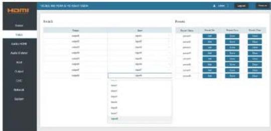
You can perform the following operations on the Video page:
① Output: The current device's OUTPUT port. Users can select signal source.
② Input: Click the drop-down menu to select signal source for the corresponding
OUTPUT port.
③ Presets Name: Name the current scene with maximum length of 12 characters.
④ Presets: Restore the settings of the last saved audio-video matrix configuration.
⑤ Presets Save: Save audio-video matrix switching configuration.
⑥ Presets Clear: Clear the saved audio-video matrix switching configuration.
■ Audio-HDMI Page

You can do the following operations on the Audio-HDMI page:
(5) HDMI Audio channel of the current Output
■ Audio-Extract Page
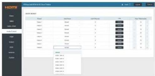
Users can perform the following operations on the Audio-Extract page:
① Channel: Audio output channel for coaxial audio or analog audio.
② Audio Source: The input source of the current audio channel. You can switch the input
source by clicking the corresponding drop-down box to select the desired input source.
③ Audio Delay: Set the output delay. You can modify it by entering the corresponding value (range: 0 \~ 300) in the input box.
④ Mute: You can mute or unmute the audio output channel by clicking the blue button.
© Audio Volume (Analog): You can set the volume value (range: 0\~30) for the analog
output channel by clicking "-" / "+" or entering the value in the input box.
■ Input Page

Users can perform the following operations on the Input page:
⑤ Inverse: Level channel of the device
Set EDID for the User
Click the "Browse" button, then select the bin file. If you select the wrong EDID file, there will be a prompt, as shown in the following figure:

Make sure to select the correct file, then you can check the name of the selected file. Select "User 1" or "User 2", then click "Upload". After successful setting, it will prompt as follows:

Download the EDID File for the Corresponding Input Channel
Click the drop-down box of "Select EDID File" to select the corresponding input channel. Then click "Download" to download the corresponding EDID file.
■ Output Page
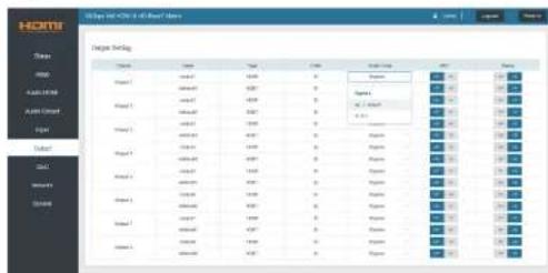
Users can perform the following operations on the Output page:
⑤ Scaler Mode: Set the current output resolution mode.
⑥ ARC: Turn on/off the ARC function.
⑦ Stream: Turn on/off the output stream.
■ CEC Page
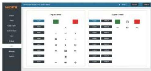
Users can perform CEC management on this page:
① Input Control: Control the operation of each input source by pressing the iconson the
page
② Output Control: Control the operation of each display, such as power on/off,
volume +/-, active source switching.
■ Network Page

Set the Default Network
Click "Set Network Defaults" button, there will be a prompt, as shown in the following figure:

Click "OK" to search the IP Address again, as shown in the following figure:

After searching is completed, it will switch to the login page, the default network setting is completed.
Modify User Password
Click the "User" button, enter the correct Old Password, New Password, and Confirm Password, then click "Save". After successful modification, there will be a prompt, as shown in the following figure:

Note: Input rules for changing passwords:
Modify Network Setting
Modify the Mode/IP Address/Gateway/Subnet Mask/Telnet Port as required, click "Save" to save the settings, then it will come into effect.
After modification, if the Mode is "Static", it will switch to the corresponding IP Address; if the Mode is "DHCP", it will automatically search and switch to the IP Address assigned by the router.

■ System Page
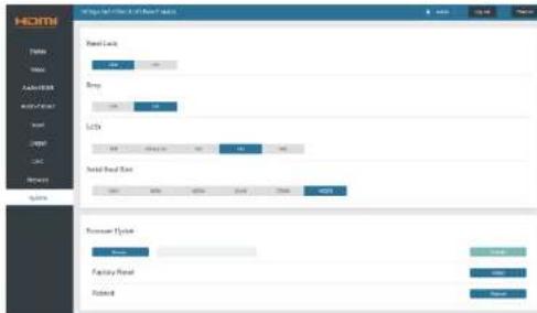
① Panel Lock: Click "Panel Lock" to lock/unlock panel buttons. "On" indicates that panel buttons are unavailable; "Off" indicates panel buttons are available.
② Beep: Click "Beep" to turn on/off the beep.
③ LCD: You can turn on/off the LCD, and set the turn-on time (15s/30s/60s).
④ Serial Baud Rate: Click the value to set the Serial Baud Rate.
⑤ Firmware Update: Click "Browse" to select the update file, then click "Update" to complete firmware update.
⑥ Factory Reset: You can reset the machine to factory defaults by clicking "Reset".
⑦ Reboot: You can reboot the machine by clicking "Reboot".
12. RS-232 Control Command
The product also supports RS-232 control. You need a serial cable with RS-232 male head and DB9 transfer USB male head. The RS-232 head of the serial cable is connected to the RS-232 control port with DB 9 at the rear of the Matrix, and the USB head of the serial cable is connected to a PC. The connection method is as follows:
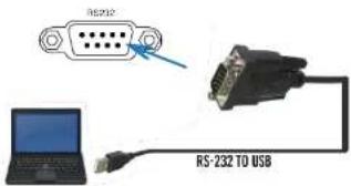
Then, open a Serial Command tool on PC to send ASCII command to control the Matrix.
The ASCII command list about the product is shown as below.
| ASCII Command | ||||
| Serial port protocol. Baud rate: 115200, Data bits: 8bit, Stop bits:1. Check bit: 0 | ||||
| x - Parameter 1y - Parameter 21 - Dclimiter | ||||
| ASCII Command | Function Description | Example | Feedback | Default Setting |
| Power | ||||
| s power z! | Power on/off the devioa,z=0-1(z=0 power off, z=1 power on) | s power 1! | Power onSystem Initializing...Initialization Finishedpower offPOWER 0 | power on |
| r power! | Get current power state | r power! | power onpower off | |
| s reboot! | Reboot the device | s reboot! | Reboot...System Initializing...Initialization Finished!FW version 1.00.01 | |
| System Setup | ||||
| hlop! | List all commands | hlop! | ||
| r type! | Get device model | r type! | HDM B88H10GP | |
| Get the unit all status | ||||
| ASCII Command | Function Description | Example | Feedback | Default Setting |
| r fw version! | Get Firmware version | r fw version! | MCU BOOT: V1.00.02MCU APP: V1.00.01WED GUI: V1.01 | |
| r link in x! | Get the connection status of the x input port, x-0~8(0-all) | r link in 1! | hdmi input 1: connect | |
| r link out y! | Get the connection status of the y output port, y-0~8(0-all) | r link out 1! | hdmi output 1: connecthdmi output 1: connect | |
| s reset! | Reset to factory defaults | s reset! | Reset to factory defaultSystem Initializing...initialization Finished!FW version 1.00.01 | |
| s beep z! | Enable/Disable buzzer function,z-0~1(z-0 beep off, z-1 beep on) | s beep 1! | beep onbeep off | beep on |
| r beop! | Get buzzer state | r beop! | boop on / boop off | |
| s lock z! | Lock/Unlock front panel button,z-0~1 (z-0 lock off, z-1 lock on) | s lock 1! | panel button lock onpanel button lock off | panel button lock off |
| r lock! | Got panel button lock state | r lock! | panel button lock on/off | |
| s lod on time z! | Sot LCD screen romain on time,z-0~4 (0/off, 1:always on, 2:15s,3:30s, 4:60s) | s lod on time 1! | lod on always | lod on 30 seconds |
| r lod mode! | Get the backlight status of lod screen | r lod mode! | lod on always | |
| s save preset z! | Save switch side between all output port and the input port to preset z, z-1~8 | s save preset 1! | save to preset 1 | |
| s recall preset z! | Call saved preset z scenarios,z-1~8 | s recall preset 1! | recall from preset 1 | |
| s clear preset z! | Clear stored preset z scenarios,z-1~8 | s clear preset 1! | clear preset 1 | |
| r prosot z! | Get preset z information, z-1~8 | r prosot 1! | video/audio crosspoint | |
| s pip! | s pip! | pip | pip | |
| Output Setting | ||||
| s in x av out y! | Set input x to output y,x=1~8, y=0~8(0=all) | s in 1 av out 2! | input 1 -> output 2 | input 1 -> output 1Input 2 -> output 2Input 3 -> output 3Input 4 -> output 4Input 5 -> output 5Input 6 -> output 6Input 7 -> output 7Input 8 -> output 8 |
| r av cut y! | Get output y signal statusy-0~8(0-all) | r av cut 0! | input 1 -> output 1Input 2 -> output 2......input 7 -> output 7Input 8 -> output 8 | |
| s hdmi y stream z! | Set hdmi output y stream on/off,y-0~8(0-all) | s hdmi 1 stream 1 | Enable hdmi output 1streamDisable hdmi output 1Stream | Enable hdmi all |
| s hdtot y stream z! | Set hdtot output y stream on/off,y=0-8(0-all)z=0-1(0, disable, tanable) | s hdtot 1 stream 1s hdtot 0 stream 1 | Enable hdtot output 1 streamDisable hdtot output 1 streamEnable hdtot all outputs streamDisable hdtot all outputs stream | Enable hdtot all outputs stream |
| r hdtot y stream! | Get hdtot output y stream status,y=0-8(0-all) | r hdtot 1 stream! | Enable hdtot output 1 streamDisable hdtot output 1 stream | |
| s hdmiy scaler z! | Set hdmiy output y port output scaler mode,y=0-8(0-all),z=1-3(1-bypass,2=4k-1080p,3sAuto) | s hdmiy 1 scaler 1s hdmiy 0 scaler 1 | hdmiy output 1 set to bypass modehdmily all outputs set to bypass mode | hdmily all outputs set to bypass |
| r hdmiy scaler! | Get hdmiy output y port output mode y=0-8(0-all) | r hdmiy 1 scaler! | hdmiy output 1 set to bypass mode | |
| s hdtoy scaler z! | Set hdtoy output x port output scaler mode,y=0-8(0-all),z=1-3(1-bypass,2-4k-1080p,3sAuto) | s hdtoy 1 scaler 2s hdtoy 0 scaler 2 | hdtoy output 1 set to 4k->1080p modehdtoy all outputs set to 4k->1080p mode | hdtoy all outputs set to bypass |
| r hdtoy scaler ! | Get hdtoy output y port output scaler mode y=0-8 (0-all) | r hdtoy 1 scaler ! | hdtoy output 1 set to 4k->1080p mode | |
| EDID Setting | ||||
| s solid in x from z! | Set Input x EDID from defaultEDID 2,3=0-8(0-40),2=1-3(1-1000p, stereo Audio 2.02=1000p,LoLoyy-DTS 5.12=1000p,Duoioy DTS 7.14=1000,p stereo Audio 2.05=1000,p,LoLoyy DTS 7.16=1000,p,Duoioy DTS 7.17=30,Stereo Audio 2.08=30,DoLoyy DTS 0.19=30,Du Audio 7.110=4KZK30 444 Stereo Audio 2.011=4KZK30 444 Doby-DTS 5.112=4KZK30 444 HD Audio 7.113=4KZK30 444 Stereo Audio 2.014=4KZK30 444,Doby-DTS 5.115=4KZK30 442 HD Audio 7.116=4KZK30 444 Stereo Audio 2.017=4KZK30 444,Doby-DTS 5.118=4KZK30 444 HD Audio 7.119=4KZK30 444,DoLoyy-DTS 5.1HUH20=4KZK30 444,Doby-DTS 5.1HUH21=4KZK30 444 HD Audio 7.1HUH22=User123=User224=31-copy from hdmiy output 1-832-39-copy from hdtot output 1-8 | s cdd in 1 from 11 | IN1 EDID:1080o,Stereo Audio 2.0 | IIN1: 1080p,Stereo Audio 2.0IN2: 1080p,Stereo Audio 2.0IN3: 1080p,Stereo Audio 2.0IN4: 1080p,Stereo Audio 2.0IN5: 1080p,Stereo Audio 2.0IN6: 1080p,Stereo Audio 2.0IN7: 1080p,Stereo Audio 2.0IN8: 1080p,Stereo Audio 2.0 |
| r e did in x! | Get EDID status of the input x, y=0-8(0-all input) | r e did in 0! | IN1 EDID: 4K2K50_444,Stereo Audio 2.0 IN2 EDID: 4K2K50_444,Stereo Audio 2.0 IN3 EDID: 4K2K50_444,Stereo Audio 2.0 IN4 EDID: 4K2K50_444,Stereo Audio 2.0 IN5 EDID: 4K2K50_444,Stereo Audio 2.0 IN6 EDID: 4K2K50_444,Stereo Audio 2.0 IN7 EDID: 4K2K50_444,Stereo Audio 2.0 IN8 EDID: 4K2K50_444,Stereo Audio 2.0 | |
| r e did data hdmi y! | Got the EDID data of the hdmi output y port, y=1-8 | r e did data hdmi 1! | EDID: 00 FF FF FF FF FF FP 00...... | |
| r e did data hdbi y! | Got the EDID data of the hdbi output y port, y=1-8 | r e did data hdbi 1! | EDID: 00 FF FF FF FF FF FP 00...... | |
| r internal edid! | Got all built-in EDID information for unit support | r internal edid! | 1.1080p,Stereo Audio 2.02.1080p,Dolby/CTS 5.13.1080p,HD Audio 7.11.1080p,Stereo Audio 2.0....20.4K2K60, Dolby/ DTS 5.1 HDR21.4K2K60, HD Audio 7.1 HDR | |
| Audio Setting | ||||
| s hdmi y arc z! | Turn on/off ARC of HDMI output y, y=0-8(0-all) z=0-1(z=0,off,z=1 on) | s hdmi 1 arc 1! s hdmi 0 arc 1! | hdmi output 1 arc on hdmi output 1 arc off hdmi all outputs are on hdmi all outputs are off | hdmi all outputs are off |
| r hdmi y arc! | Got the ARC state of HDMI output y, y=0-8(0-all) | r hdmi 1 arc! | hdmi output 1 arc on | |
| s hdtot y arc z! | Turn on/off ARC of HDBT output y y=0-8(0-all) z=0-1(z=0,off,z=1 on) | s hdtot 1 arc 1! s hdtot 0 arc 1! | hdtot output 1 arc on hdtot output 1 arc off hdtot all outputs are on hdtot all outputs are off | hdtot all outputs are off |
| r hdtot y arc! | Got the ARC state of HDMI output y, y=0-8(0-all) | r hdtot 1 arc! | hdtot output 1 arc on | |
| y out y audio from z | Set HDMI/HDBT output audio y=0-8(0-all),z=0-28 z=0. Default z=1-8 from HDMI input 1-8 z=9-16 from HDMI out 1-8 ARC | s out 1 audio from 1 | HDMI/HDBT output 1 audio from HDMI input 1 | HDMI/HDBT all outputs from |
| s coax_analog out y audio from z! | Set coaxial output audio y=0-8 (0-all), z=1-26 z=1-8 from HDMI input 1-8 z=9-16 from HDMI out 1-8 ARC z=17-24 from HDBT cut 1-8 ARC z=28-28 from encoded audio 1-4 | s coax_analog out 1 audio from 1! s coax_analog out 0 audio from 1! | Coaxial_Analog output audio: from HDMI input 1 Coaxial_Analog all outputs audio: from HDMI input 1 | Coaxial_Analog all outputs audio: from HDMI input 1 |
| s coax_analog out y audio delay z! | Set coax_analog output audio delay y=0-8(0-all), z=0-300ms | s coax_analog out 1 audio delay 100! s coax_analog out 0 audio delay 100! | Coaxial_Analog output audio delay 100ms Coaxial_Analog all outputs audio delay 100ms | Coaxial_Analog all outputs audio delay 100ms |
| s coax_analog out y audio vol z! | Sot analog output audio volume y=0-8(0-all), z=0-30, +; : | s analog out 1 audio vol 30! s analog out 1 audio vol -! s analog out 0 audio vol 30! s analog out 0 audio vol -! | Analog output 1 audio volume 30 Analog all outputs audio volume 30 | all Analog output audio volume 20 |
| s coax_analog out y audio mute z! | Mute on/off coax_analog output audio y=0-8(0-all), z=0-1 (z=0 off, z=1 on) | s coax_analog out 1 audio mute 1! | Mute coax_analog output 1 audio | Mute off all coax_analog out audio |
| r coax_analog out y audio! | Get coax_analog output audio status y=0-8(0-all) | r coax_analog out 1 audio! | Coaxial_Analog output 1 audio from HDMI input 1 Coaxial_Analog output 1 audio delay 0ms Analog output 1 audio volume 20 Mute off coax_analog output 1 audio | |
| CEC Setting | ||||
| s oce in x on! | set input x power on by CEC, x=0-8(0-all input) | s oce in 1 on! | input 1 power on | |
| s oce in x off! | set input x power off by CEC, x=0-8(0-all input) | s oce in 1 off! | input 1 power off | |
| s cec in x menu! | set input x open menu by CEC, x=0-8(0-all input) | s cec in 1 menu! | input 1 open menu | |
| s oce in x back! | set input x back operation by CEC, x=0-8(0-all input) | s oce in 1 back! | input 1 back operation | |
| s cec in x up! | set input x menu up operation by CEC, x=0-8(0-all input) | s cec in 1 up! | input 1 menu up operation | |
| s oce in x down! | set input x menu down operation by CEC, x=0-8(0-all input) | s oce in 1 down! | input 1 menu down operation | |
| s oce in x left! | set input x menu left operation by CEC, x=0-8(0-all input) | s oce in 1 left! | input 1 menu left operation | |
| s cec in x stop! | set Input x stop by CEC, x=0-8(0-all input) | s cec in 1 stop! | input 1 stop operation | |
| s cec in x new! | set Input x rewind by CEC, x=0-8(0-all input) | s cec in 1 new! | input 1 rewind operation | |
| s cec in x mute! | set Input x volume mute by CEC, x=0-8(0-all input) | s cec in 1 mute! | input 1 volume mute | |
| s cec in x vol-! | set Input x volume down by CEC, x=0-8(0-all input) | s cec in 1 vol-! | input 1 volume down | |
| s cec in x vol+! | set Input x volume up by CEC, x=0-8(0-all input) | s cec in 1 vol+! | input 1 volume up | |
| s cec in x t!! | set Input x fast forward by CEC, x=0-8(0-all input) | s cec in 1 t!! | input 1 fast forward operation | |
| s cec in x previous! | set Input x previous by CEC, x=0-8(0-all input) | s cec in 1 previous | input 1 previous operation | |
| s cec in x next! | set Input x next by CEC, x=0-8(0-all input) | s cec in 1 next! | input 1 next operation | |
| s cec hdmi out y on! | set hdmi output y power on by CEC, y=0-8(0-all hdmi output) | s cec hdmi out 1 on! | hdmi output 1 power on | |
| s cec hdbt out y on! | set hdbt output y power on by CEC, y=0-8(0-all hdbt output) | s cec hdbt out 1 on! | hdbl output 1 power on | |
| s cec hdmi out y off! | set hdmi output y power off by CEC, y=0-8(0-all hdmi output) | s cec hdmi out 1 off! | hdmi output 1 power off | |
| s cec hdbt out y off! | set hdbt output y power off by CEC, y=0-8(0-all hdbt output) | s cec hdbt out 1 off! | hdbl output 1 power off | |
| s cec hdmi out y mute! | set hdmi output y volume mute by CEC, y=0-8(0-all hdmi output) | s cec hdmi out 1 mute! | hdmi output 1 volume mute | |
| s cec hdbt out y mute! | set hdbt output y volume mute by CEC, y=0-8(0-all hdbt output) | s cec hdbt out 1 mute! | hdbt output 1 volume mute | |
| s cec hdmi out y vol-! | set hdmi output y volume down by CEC, y=0-8(0-all hdmi output) | s cec hdmi out 1 vol-! | hdmi output 1 volume down | |
| s cec hdbt out y vol-! | set hdbt output y volume down by CEC, y=0-8(0-all hdbt output) | s cec hdbt out 1 vol-! | hdbl output 1 volume down | |
| s cec hdmi out y vol-! | set hdmi output y volume up by CEC, y=0-8(0-all hdmi output) | s cec hdmi out 1 vol-! | hdmi output 1 volume up | |
| s cec hdbt out y vol-! | set hdbt output y volume up by CEC, y=0-8(0-all hdbt output) | s cec hdbt out 1 vol-! | hdbt output 1 volume up | |
| s cec hdmi out y active! | set hdmi output y active source by CEC, y=0-8(0-all hdmi output) | s cec hdmi out 1 active! | hdmi output 1 active source | |
| s cec hdbt out y active! | set hdbt output y active source by CEC, y=0-8(0-all hdbt output) | s cec hdbt out 1 active! | hdbl output 1 active source | |
| Network Setting | ||||
| r ipcontig! | Get the Current IP Configuration | r ipcontig! | IP Modc: DHCP IP:192.168.62.106Subset Mask: 255.255.255.0Gateway:192.168.62.1TCP/IP port:8000 | |
| s ip mode z! | Set network IP mode to static IP or DHCP, z=0~1 (z=0 Static, z=1 DHCP) | s ip mode 0! | Set IP mode:Static (Please use "s net reboot" command or repower device to apply new config!) | DHCP ON |
| r ip mode! | Get network IP mode | r ip mode! | IP Mode: DHCP | |
| s ip addr xxx.xxx.xxx.xxx! | Set network IP address | s ip addr 192.168.1.100! | Set IP address: 192.168.1.100 (Please use "s net reboot" command or repower device to apply new config!) DHCP on, Device can't config static address, set DHCP off first. | |
| r ip addr! | Get network IP address | r ip addr! | IP.192.168.62.105 | |
| s subnet xxx.xxx.xxx.xxx! | Set network subnet mask | s subnet 255.255.255.0! | Set subnet Mask address:255.255.255.0 (Please use "s net reboot" command or repower device to apply new config!) DHCP on, Device can't config subnet mask, set DHCP off first. | |
| r subnet! | Get network subnet mask | r subnet! | Subnet Mask: 255.255.255.0 | |
| s gateway xxx.xxx.xxx.xxx! | Set network gateway | s gateway 192.168.1.1! | Set gateway: 192.168.1.1 Please use "s not reboot" command or repower device to apply new config! DHCP on, Device can't config gateway, set DHCP off first. | |
| r gateway! | Get network gateway | r gateway! | Gateway:192.168.1.1 | |
| s tcp/rip port x! | Set network TCP/IP port (x=1~65535) | s tcp/rip port 8000! | Set TCP/IP port:8000 | Set tcp/rip port:8000 |
| r tcp/rip port! | Get network TCP/IP port | r tcp/rip port! | TCP/IP port:8000 | |
| a telnet port x! | Set network telnet port (x=1~65535) | a telnet port 23! | Set Telnet port:23 | Set telnet port:23 |
| r telnet port! | Get network telnet port | r telnet port! | Telnet port:23 | |
| s not reboot! | Roboot network modulus | s not reboot! | Search for IP, Please wait...!IP Modo: DHCP IP:192.168.62.111 Subnet Mask: 255.255.255.0 Gateway:192.168.62.1TCP/IP port:8000 Telnet port:23 | |
| s uart x baudrate y! | Set the baudrate of x local and hobt uart, x=0-16, y=1-8, 1: 115200/Default 2: 57600 3: 56000 4:38400 5:19200 6:14400 7:5600 8:4500 | s uart 1 baudrate 1 | LocalUARTd Baudrate is 115200 | |
| s uart x parity y! | Set the Parity of x local and hobt uart, x=0-16, y=1-3, 1: none 2:odd 3:even | s uart x parity 1! | LocalUART 1 Parity Is None | |
| s uart x type z sondata y end! | Sond data y from x local and hobt uart, z=0 ascii, z=1 hex, x=0-16 | s uart 1 type 0 sondata abodotg end! | LocalUART1 data abodotg | |
| r uart status x! | Get the Status of x local and hobt uart, x=0-16 | r uart status 1! | ||
- Application Example

Before contacting tech support, we may have answered your question already! Visit our BZBGEAR support page at bzbgear.com/support for valuable information on our products.
Here you will find our Knowledge Base (bzbgear.com/knowledge-base) consisting of tutorials, quick start guides, and step-by-step troubleshooting instructions. Also visit our YouTube channel BZB TV at youtube.com/c/BZBTVchannel for help setting up, connecting, and other how-to videos regarding our products.
If you still need answers, please call 1.888.499.9906, email support@bzbgear.com, or chat at bzbgear.com.
15. Warranty
BZBGEAR Pro AV products and Cameras come with a three-year warranty. An extended two-year warranty is available for our Cameras upon registration for a total of five years.
For an extended two-year warranty on our Cameras, follow these steps:
-
Register your Camera within 90 days of purchase by visiting bzbgear.com/warranty.
-
Complete the registration form. Provide all necessary proof of purchase details, including serial number and a copy of your sales receipt.
For complete warranty information, please visit bzbgear.com/warranty or scan the QR code below.

16. Mission Statement
BZBGEAR manifests from the competitive nature of the audiovisual and live streaming industry to innovate while keeping the customer in mind. AV solutions can cost a pretty penny, and new technology only adds to it. We believe everyone deserves to see, hear, and feel the advancements made in today's AV world without having to break the bank. BZBGEAR is your answer for applications requiring the latest pro AV and live streaming solutions.
You'll notice comparably lower prices with BZBGEAR while the performance and quality are on par with the top brands in the industry. Our team offers system design consultation and expert
- Thank you for purchasing this product
- Surge protection device recommended
- Table of Contents
- Introduction
- Features
- Package Contents
- Operation Controls and Functions
- IR Remote
- IR Control System
- IR Cable Pin Assignment
- EDID Management
- Matrix Audio and RS-232 Introduction
- Web GUI User Guide
- ■ Status Page
- ■ Audio-Extract Page
- ■ Input Page
- Set EDID for the User
- Download the EDID File for the Corresponding Input Channel
- ■ Output Page
- Set the Default Network
- Modify User Password
- Modify Network Setting
- ■ System Page
- RS-232 Control Command
- Warranty
- Mission Statement
Brand : BZBGear
Model : BG-UM88-100M
Category : Router