BG-UHD-KVM41 - KVM switch BZBGear - Free user manual and instructions
Find the device manual for free BG-UHD-KVM41 BZBGear in PDF.

User questions about BG-UHD-KVM41 BZBGear
0 question about this device. Answer the ones you know or ask your own.
Ask a new question about this device
Download the instructions for your KVM switch in PDF format for free! Find your manual BG-UHD-KVM41 - BZBGear and take your electronic device back in hand. On this page are published all the documents necessary for the use of your device. BG-UHD-KVM41 by BZBGear.
USER MANUAL BG-UHD-KVM41 BZBGear
HDMI 2.0 4x1 Switcher with KVM USB3.0
natural_image
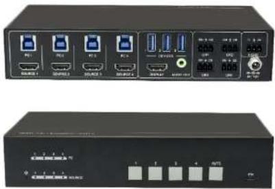
Two black electronic device units with ports and indicator lights, no visible text or symbols on the surfaces.Preface
Read this user manual carefully before using the product. Pictures shown in this manual are for reference only. Different models and specifications are subject to real product.
This manual is only for operation instruction, please contact the local distributor for maintenance assistance. The functions described in this version were updated till August, 2019. In the constant effort to improve the product, we reserve the right to make functions or parameters changes without notice or obligation. Please refer to the dealers for the latest details.
FCC Statement
This equipment generates, uses and can radiate radio frequency energy and, if not installed and used in accordance with the instructions, may cause harmful interference to radio communications. It has been tested and found to comply with the limits for a Class B digital device, pursuant to part 15 of the FCC Rules. These limits are designed to provide reasonable protection against harmful interference in a commercial installation.
Operation of this equipment in a residential area is likely to cause interference, in which case the user at their own expense will be required to take whatever measures may be necessary to correct the interference.
Any changes or modifications not expressly approved by the manufacture would void the user's authority to operate the equipment.


SAFETY PRECAUTIONS
To ensure the best from the product, please read all instructions carefully before using the device. Save this manual for further reference.
- Unpack the equipment carefully and save the original box and packing material for possible future shipment.
- Follow basic safety precautions to reduce the risk of fire, electrical shock and injury to persons.
- Do not dismantle the housing or modify the module. It may result in electrical shock or burn.
- Using supplies or parts not meeting the products' specifications may cause damage, deterioration or malfunction.
• Refer all servicing to qualified service personnel. - To prevent fire or shock hazard, do not expose the unit to rain, moisture or install this product near water.
- Do not put any heavy items on the extension cable in case of extrusion.
- Do not remove the housing of the device as opening or removing housing may expose you to dangerous voltage or other hazards.
- Install the device in a place with fine ventilation to avoid damage caused by overheat.
- Keep the module away from liquids.
- Spillage into the housing may result in fire, electrical shock, or equipment damage. If an object or liquid falls or spills on to the housing, unplug the module immediately.
- Do not twist or pull by force ends of the cable. It can cause malfunction.
- Do not use liquid or aerosol cleaners to clean this unit. Always unplug the power to the device before cleaning.
- Unplug the power cord when left unused for a long period of time.
- Information on disposal for scrapped devices: do not burn or mix with general household waste, please treat them as normal electrical wastes.
Table of Contents
- Product Introduction .... 1
1.1 Features....1
1.2 Package List....2
-
Specification 3
-
Panel Description .... 4
3.1.1 Front Panel 4
3.1.2 Rear Panel 5
- System Connection ....6
4.1 Usage Precaution....6
4.2 System Diagram....6
- Button Control....7
- Table Grommet Control 7
- RS232 Control 8
7.1 RS232 Control Software 8
7.2 RS232 Command....10
7.2.1 Device Control....10
7.2.2 Signal Switching....11
7.2.3 Audio Setting 11
7.2.4 EDID Management....12
7.2.5 HDCP Setting 12
7.2.6 Baudrate Setting 13
7.2.7 Display Control....13
- Firmware Upgrade....14
- Panel Drawing 15
- Troubleshooting & Maintenance....16
- Customer Service 17
- Second Year Assurance .... 18
- Mission Statement.... 19
1. Product Introduction
Thanks for choosing the professional BG-UHD-KVM41 HDMI 2.0 4x1 Switcher. The switcher features four HDMI video inputs and one HDMI output. It supports HDMI video resolution up to 4Kx2K@60Hz 4:4:4 HDR 10 and Dolby Vision. The switcher provides one stereo audio output for audio de-embedding, and provides four type-B USB ports and three type-A USB ports for KVM management, the four HDMI computers can be controlled via one keyboard, one mouse and one monitor. In addition, the switcher features four GR ports to connect BG-SC-GRHU table grommets for source selection and black screen setting. The switcher can also be controlled via RS232 and front panel buttons.
1.1 Features
• 4x1 HDMI 2.0 Switcher with KVM.
• Supports video resolution up to 4Kx2K@60Hz 4:4:4, HDR 10 and Dolby Vision.
• HDCP 2.2 compliant.
• Compatible with Windows, Linux and Mac OS.
• 3.5mm stereo audio output for audio de-embedding.
- Convenient and cost-effective USB 3.0 peripheral sharing.
- Controls four HDMI computers via one keyboard, one mouse and one monitor.
• KVM auto-switching based on TMDS/5V detection.
- Controllable by buttons, RS232 commands and BG-SC-GRHU table grommets.
- Simplifies wiring for easy installation.
1.2 Package List
• 1x BG-UHD-KVM41HDMI 2.0 4x1 Switcher
• 2x Mounting Ears with 4 Screws
- 4x Plastic Cushions
- 4x 3-pin Terminal Blocks
• 1x RS232 Cable (3-pin to DB9)
• 1x Power Adapter (12V DC 2A)
• 1x User Manual
Note: Please contact your distributor immediately if you found any damage or defect in the components.
- Specification
| Video Input | |
| Input | (4) SOURCE 1~4 |
| Input Connector | (4) Female type-A HDMI |
| HDMI Input Resolution | Up to 4Kx2K@60Hz 4:4:4, HDR10, Dolby Vision |
| HDMI Standard | 2.0 |
| HDCP Version | 2.2 |
| Video Output | |
| Output | (1) DISPLAY |
| Output Connector | (1) Female type-A HDMI |
| HDMI Output Resolution | Up to 4Kx2K@60Hz 4:4:4, HDR10, Dolby Vision |
| HDMI Standard | 2.0 |
| HDCP Version | 2.2 |
| Audio | |
| Output | (1) AUDIO OUT |
| Output Connector | (1) 3.5mm mini stereo audio jack |
| Audio Format | PCM 2CH |
| Frequency Response | 20Hz to 20KHz, +1dB |
| Max Output Level | 2.0Vrms ± 0.5dB, 2V = 16dB headroom above -10dBV (316 mV) nominal consumer line level signal. |
| THD+N | < 0.05%, 20Hz - 20KHz bandwidth, 1KHz sine at 0dBFS level (or max level). |
| SNR | >80dB, 20Hz - 20KHz bandwidth. |
| Crosstalk Isolation | <-80 dB, 10 kHz sine at 0dBFS level (or max level before clipping). |
| L-R Level Deviation | < 0.05 dB, 1 kHz sine at 0dBFS level (or max level before clipping). |
| Output Load Capability | 1Kohm and higher (supports 10x parallelled 10k ohm loads). |
| Noise Level | -80dB |
| Control | |
| General | |
| Bandwidth | 18Gbps |
| Operation Temperature | -10°C ~ +55°C |
| Storage Temperature | -25°C ~ +70°C |
| Relative Humility | 10%-90% |
| Type-A USB Power Supply | 1A |
| System Power Supply | Input: 100V~240V AC; Output: 12V DC 2A |
| System Power Consumption | 14W(Max) |
| Dimension (W*H*D) | 200mm x 40mm x 100mm |
| Net Weight | 685g |
3. Panel Description
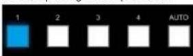
3.1.1 Front Panel
text_image
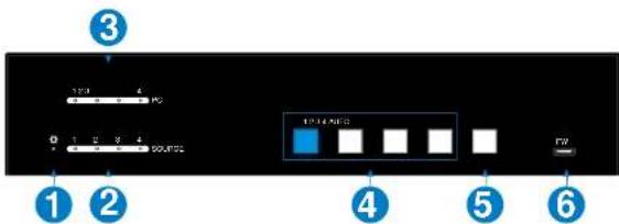
3 1 2 4 0 1 2 3 4 SOURCE 17:46:00 4 5 FW① POWER LED: The LED illuminates red when power is applied.
② PC LEDs: Total four LEDs, any one of which illuminates blue to indicate its corresponding type-B USB port is connected to an active PC.
③ SOURCE LEDs: Total four LEDs, any one of which illuminates blue to indicate its corresponding HDMI port is connected to an active source device.
④ SOURCE BUTTONs: Four buttons for input source selection, one of which illuminates blue to indicate which source device is selected.
⑤ AUTO: Press it to enable auto switching mode, and it will illuminate blue. Press
the HUG Table Grommet
3.1.2 Rear Panel


text_image
PC 1752-2752-3752 PC 1752-2752-3752-4 PC 1752-2752-3752-4 PC 1752-2752-3752-4 PC 1752-2752-3752-4 PC 1752-2752-3752-4 PC 1752-2752-3752-4 PC 1869-1869-1869-1869-1869-1869-1869-1869-1869-1869-1869-1869-1869-1869-1869-1869-1869-1869-1869-1869-1869 PC 1869-1869-1869-1869-1869-1869-1869-1869-1869-1869-1869-1869-1869-1869-1869-1869-1869-1869-1869 PC 1874-1874-1874-1874-1874-1874-1874-1874-1874-1874-1874-1874-1874-1874-1874-1874-1874-1874-1874-1874-1874 PC 1874-1874-1874-1874-1874-1874-1874-1874-1874-1874-1874-1874-1874-1874-1874-1874


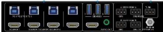
① SOURCE1\~SOURCE4: Four type-A female HDMI Input ports to connect HDMI source devices (PC, Blu-ray Disc™ or DVD player, etc.).
② PC1\~PC4: Four type-B USB ports to connect PCs. The PC can be a source device connected to the corresponding HDMI Input port.
③ DEVICES (1\~3): Three type-A USB ports to connect USB devices (Keyboard, Mouse or camera, etc.). These USB devices are used to control the PC which is connected to the selected HDMI input port and the corresponding type-B USB port. These type-A USB ports can power these USB devices with 1A.
④ DISPLAY: Type-A female HDMI output port to connect display device (e.g. Projector).
⑤ AUDIO OUT: 3-pin terminal block to connect speakers or amplifiers for audio output.
⑥ GR1\~GR4: Four 3-pin terminal blocks to connect four BG-SC-GRHU table grommets for source selection and black screen setting.
⑦ RS232: 3-pin terminal blocks to a control device (e.g. PC) to control the switcher.
⑧ DC 12V: Power port for power adapter connection.
4. System Connection
4.1 Usage Precaution
• Make sure all components and accessories included before installation.
- System should be installed in a clean environment with proper temperature and humidity.
- All of the power switches, plugs, sockets, and power cords should be insulated and sale.
- All devices should be connected before power on
4.2 System Diagram
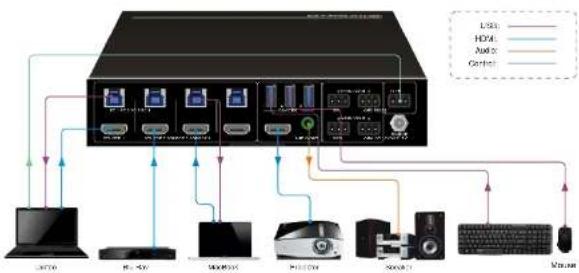
The following diagrams illustrate typical input and output connections that can be utilized with this switcher:
The switcher is used alone:
flowchart
graph TD
    A["Host"] --> B["Server"]
    B --> C["Microcontroller"]
    C --> D["Desktop"]
    D --> E["Monitor"]
    E --> F["Audio"]
    E --> G["Control"]
    H["LSSS"] --> I["Server"]
    I --> J["Microcontroller"]
    J --> K["Desktop"]
    K --> L["Microcontroller"]
    L --> M["Audio"]
    L --> N["Control"]
5. Button Control
- Manual Switching
Press button 1\~4 to the corresponding HDMI input source.
• Auto Switching
Press AUTO to enable auto switch mode, and then the button LED will illuminate blue.
When in auto mode, the switcher follows the rules in the certain circumstances:
√ The switcher will automatically switch to the first available active input starting at input 1 to 4.
√ Press the source button (1, 2, 3 or 4) can directly change the input source.
√ New Input: Upon detecting a new input, the switcher will automatically select the new source.
√ Detection input signal source: 5V(Default) or TMDS.
√ Reboot: Once power is restored to the switcher, if the last selected source is still available, the switcher will still output this signal, otherwise, the switcher will switch to the first available active input starting at input 1.
√ Source Removed: When an active source is removed, the switcher will switch to the first available active input starting at input 1.
- Press AUTO again can exit auto switch mode, but the input source will remain the current setting.
Note: The factory default is auto switching mode.
6. Table Grommet Control
The BG-SC-GRHU table grommet can be used for input source selection and black screen.
Press Show Me on table grommet to select HDMI source.
Press Black Output on table grommet to let display be black screen.
7. RS232 Control
Connect the switcher to the control device (e.g. PC) with RS232 cable and set the parameters in the right manner, the control device is capable to control this switcher by RS232 commands.
7.1 RS232 Control Software
Installation: Copy the control software file to the computer connected with this switcher.
Uninstallation: Delete all the control software files in corresponding file path.
Basic Settings
First of all, please connect all needed input devices and output devices, then to connect it with a computer which is installed with RS232 control software.
Here take the software CommWatch.exe as example.
Double-click the following icon:

CommWatch.exe
The interface of the control software is shown as below:
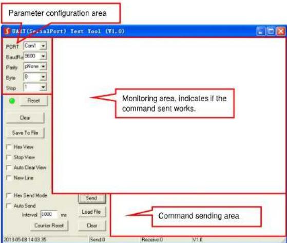
text_image
Parameter configuration area DACT(SerialPort) Test Tool (V1.0) PORT Com1 ReadRate 9600 Parity pNone Byte 0 Stop 1 Reset Clear Save To File Hex View Stop View Auto Clear View New Line Hex Send Mode Auto Send Interval 1000 ms Counter Reset Send Load File Clear Monitoring area, indicates if the command sent works. Command sending area 2013.05.08 14:03:35 Send0 Receive 0 V1.0Please set the parameters of COM number, bound rate, data bit, stop bit and the parity bit correctly, then the RS232 commands can be sent in Command Sending Area.
Baud rate: 9600;
Data bit: 8;
Stop bit: 1;
Parity bit: none.
7.2 RS232 Command
Note: All commands need to be ended with "
7.2.1 Device Control
| Command | Description | Command Example and Feedback |
| #GET_FIRMWARE_VERSION | Get the software version. | @V1.0.0 |
| #SET_KEYPAD_LOCK 0 | Unlock the front panel buttons (Factory default). | @FRONT PANEL UNLOCK! |
| #SET_KEYPAD_LOCK 1 | Lock the front panel buttons. | @FRONT PANEL LOCK! |
| #GET_KEYPAD_LOCK | Get the locking status of front panel buttons. | @FRONT PANEL UNLOCK! |
| @FRONT PANEL LOCK! | ||
| #SET_HDMI_DETECTION_MODE 0 | Set the detection method of HDMI source input to 5V. | @INPUT_SIGNAL_DETECTION 0! |
| #SET_HDMI_DETECTION_MODE 1 | Set the detection method of HDMI source input to TMDS. | @INPUT_SIGNAL_DETECTION 1! |
| #GET_HDMI_DETECTION_MODE | Get the detection method of HDMI source input. | @INPUT_SIGNAL_DETECTION 0! |
| @INPUT_SIGNAL_DETECTION 1! | ||
| #GET_STATUS | Get the system status. | @RS232 QUERY STATUS!@BG-UHD-KVM41@V1.0.0@FRONT PANEL UNLOCK!@HDMI OUT SWITCH TO AUTO MODE!@HDMI IN SWITCH TO 1!@OUTPUT HDCP 0!@INPUT_SIGNAL_DETECTION 1!@IIS OUT ON!@RS232 BAUDRATE IS 1! |
| #FACTORY_RESET | Restore factory default | @FACTORY DEFAULT!@BG-UHD-KVM41@V1.0.0@HDMI OUT SWITCH TO AUTO MODE!@OUTPUT HDCP 0!@IIS OUT ON! |
| #REBOOT | Reboot the device. | @REBOOT |
| #HELP | Get all commands and its usage. |
7.2.2 Signal Switching
| Command | Description | Command Example and Feedback |
| #SET_AV H1 | Switch to HDMI source 1. | @HDMI IN SWITCH TO 1! |
| #SET_AV H2 | Switch to HDMI source 2. | @HDMI IN SWITCH TO 2! |
| #SET_AV H3 | Switch to HDMI source 3. | @HDMI IN SWITCH TO 3! |
| #SET_AV H4 | Switch to HDMI source 4. | @HDMI IN SWITCH TO 4! |
| #GET_AV | Get the current HDMI source. | @HDMI IN SWITCH TO 1! |
| #SET_AUTO_SWITCH 1 | Enable auto switching (Factory default). | @HDMI OUT SWITCH TO AUTO MODE! |
| #SET_AUTO_SWITCH 0 | Disable auto switching | @HDMI OUT SWITCH TO MANUAL MODE! |
| #GET_AUTO_SWITCH | Get the auto switching status. | @HDMI OUT SWITCH TO AUTO MODE! |
| @HDMI OUT SWITCH TO MANUAL MODE! |
7.2.3 Audio Setting
| Command | Description | Command Example and Feedback |
| #SET_IIS 1 | Turn on stereo audio output. | @IIS OUT ON! |
| #SET_IIS 0 | Turn off stereo audio output. | @IIS OUT OFF! |
| #GET_IIS | Get the stereo audio output status. | @IIS OUT ON! |
| @IIS OUT OFF! |
7.2.4 EDID Management
| Command | Description | Command Example and Feedback |
| #SET_EDID_MODE [PARAM] | [PARAM]=0000~0011[PARAM]=0000, set the EDID mode to Pass-through (Factory default). If the source device can't read EDID from display device, it will use the built-in EDID: 3840x2160@60Hz Deep Color Sterec Audio.[PARAM]=0001/0010/0011, set the EDID of source device to user-defined EDID 0001/0010/0011. | #SET EDID MODE 0000 |
| @EDID_MODE 0000! | ||
| #GET_EDID_MODE | Get the EDID mode. | @EDID MODE 0000! |
| #EDIDR [PARAM] | Get the EDID value.[PARAM]=0000~0011 | @EDID HEX STRING OF '0000':00 FF FF FF FF FF FF 00 4100 F2 08 50 12 00 00... ... |
| #UPLOAD_USER_EDID [PARAM] | [PARAM]=0001/0010/0011, upload user-defined EDID. When the command applied, system prompts to upload the EDID file (.bin). Operation will be cancelled in 10 seconds. | #UPLOAD_USER_EDID 0001 |
| @PLEASE SEND THE EDID FILE!... ...@RECEIVED THE FILE. LENGTH=256!@EDID0001 UPDATE SUCCESSFULLY! |
7.2.5 HDCP Setting
| Command | Description | Command Example and Feedback |
| #SET_OUTPUT_HDCP 0 | Set the HDCP mode of HDMI output to PASSIVE mode (Factory default).The HDCP of HDMI output automatically follows the HDCP version of sequence.HDCP version of HDMI output is HDCP 1.4 for broader video solution.If the input video has no HDCP content,the HDMI output has no HDCP too. | @OUTPUT_HDCP 0! |
| #GET_OUTPUT_HDCP | Get the HDCP mode of HDMI output. | @OUTPUT_HDCP 0! |
7.2.6 Baudrate Setting
| Command | Description | Command Example and Feedback |
| #SET_RS232_BAUD 1 | Set RS232 baudrate to 9600. | @RS232 BAUDRATE IS 1! |
| #SET_RS232_BAUD 2 | Set RS232 baudrate to 19200 | @RS232 BAUDRATE IS 2! |
| #SET_RS232_BAUD 3 | Set RS232 baudrate to 38400 | @RS232 BAUDRATE IS 3! |
| #SET_RS232_BAUD 4 | Set RS232 baudrate to 57600 | @RS232 BAUDRATE IS 4! |
| #SET_RS232_BAUD 5 | Set RS232 baudrate to 115200 | @RS232 BAUDRATE IS 5! |
| #GET_RS232_BAUD | Get the RS232 baudrate. | @RS232 BAUDRATE IS 1! |
7.2.7 Display Control
| Command | Description | Command Example and Feedback |
| #SET_THE_DISPLAY_TO 0 | Set the display to output black screen, and no audio output. | @THE DISPLAY SIDESCREEN IS BLACK!@THE DISPLAY ISALREADY OFF! |
| #SET_THE_DISPLAY_TO 1 | Wake up the display screen. | @WAKE UP THE SCREEN!@THE DISPLAY ISALREADY ON! |
| #GET_THE_DISPLAY | Get the status of display screen. | @THE DISPLAY IS OFF! |
| @THE DISPLAY IS ON! |
8. Firmware Upgrade
Please follow the steps as below to upgrade firmware by the FW port on the front panel:
1) Prepare the latest upgrade file (.bin) and rename it as "FW_MERG.bin" on PC.
2) Power off the switcher, and connect the FW port of switcher to the PC with USB cable.
3) Power on the switcher, and then the PC will automatically detect a U-disk named of "BOOTDISK".
4) Double-click the U-disk, a file named of "READY.TXT" would be showed.
5) Directly copy the latest upgrade file (.bin) to the "BOOTDISK" U-disk.
6) Reopen the U-disk to check the filename "READY.TXT" whether automatically becomes "SUCCESS.TXT", if yes, the firmware was updated successfully, otherwise, the firmware updating is fail, the name of upgrade file (.bin) should be confirm again, and then follow the above steps to update again.
7) Remove the USB cable after firmware upgrade.
8) After firmware upgrade, the switcher should be restored to factory default by sending command.
- Panel Drawing
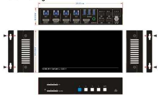
text_image
20kV 100kV 100kV 100kV 100kV 100kV 100kV 100kV 100kV 100kV 100kV 100kV 100kV 100kV 100kV 100kV 100kV 100kVBG-UHD-KVM41 Switcher
- Troubleshooting & Maintenance
| Problems | Potential Causes | Solutions |
| Output image with white noise. | Bad quality of the connecting cable. | Try another high quality cable. |
| Fail or loose connection. | Make sure the connection is good | |
| No output image when switching. | No signal at the input / output end. | Check with oscilloscope or multimeter if there is any signal at the input/ output end. |
| Fail or loose connection. | Make sure the connection is good. | |
| The switcher is broken. | Send it to authorized dealer for repairing. | |
| POWER indicator doesn't work or no respond to any operation. | Fail connection of power cord. | Make sure the power cord connection is good. |
| Cannot control the device by control device (e.g. a PC) through RS232 port. | Wrong RS232 communication parameters. | Type in correct RS232 communication parameters. |
| Broken RS232 port. | Send it to authorized dealer for checking. |
If your problem persists after following the above troubleshooting steps, seek further help from authorized dealer or our technical support.
11. Customer Service
The return of a product to our Customer Service Implies the full agreement of the terms and conditions hereinafter. There terms and conditions may be changed without prior notice.
1) Warranty
The limited warranty period of the product is one year.
2) Scope
These terms and conditions of Customer Service apply to the customer service provided for the products or any other items sold by authorized distributor only.
3) Warranty Exclusion:
- Warranty expiration.
• Factory applied serial number has been altered or removed from the product.
• Damage, deterioration or malfunction caused by:
√ Normal wear and tear.
√ Use of supplies or parts not meeting our specifications.
√ No certificate or invoice as the proof of warranty.
√ The product model showed on the warranty card does not match with the model of the product for repairing or had been altered.
√ Damage caused by force majeure.
√ Servicing not authorized by distributor.
√ Any other causes which does not relate to a product defect.
- Shipping fees, installation or labor charges for installation or setup of the product.
4) Documentation:
Customer Service will accept defective product(s) in the scope of warranty coverage at the sole condition that the defeat has been clearly defined, and upon reception of the documents or copy of invoice, indicating the date of purchase, the type of product, the serial number, and the name of distributor.
12. Warranty Information (Second Year Assurance)
BZBGEAR wants to assure you peace of mind. We're so confident in the quality of our products that along with the manufacturer's one-year limited warranty, we are offering free second-year warranty coverage upon registration!
Taking advantage of this program is simple, just follow the steps below:
-
Register your product within 90 days of purchase by visiting BZBGEAR.com/warranty.
-
Complete the registration form. Provide all necessary proof of purchase details, including serial number and a copy of your sales receipt.
For questions, please call 1.888.660.2962 or email support@bzbgear.com.
For complete warranty information, please visit BZBGEAR.com/warranty or scan the QR code below.

*Terms and conditions apply. Registration is required.
13. Mission Statement
BZBGEAR manifests from the competitive nature of the audiovisual industry to innovate while keeping the customer in mind. AV solutions can cost a pretty penny, and new technology only adds to it. We believe everyone deserves to see, hear, and feel the advancements made in today's AV world without having to break the bank. BZBGEAR is the solution for small to medium-sized applications requiring the latest professional products in AV.
We live in a DIY era where resources are abundant on the internet. With that in mind, our team offers system design consultation and expert tech support seven days a week for the products in our BZBGEAR catalog. You'll notice comparably lower prices with BZBGEAR solutions, but the quality of the products is on par with the top brands in the industry. The unparalleled support from our team is our way of showing we care for every one of our customers. Whether you're an integrator, home theater enthusiast, or a do-it-yourselfer, BZBGEAR offers the solutions to allow you to focus on your project and not your budget.