
MultiSync SX6000 - Video projector NEC - Free user manual and instructions
Find the device manual for free MultiSync SX6000 NEC in PDF.

| Product Type | Video Projector |
| Model | MultiSync SX6000 |
| Dimensions (W x D x H) | 560 mm x 682 mm x 300 mm (22.0" x 26.9" x 11.8") with lens hood and foot |
| Net Weight | 43 kg (94.8 lbs) without lens |
| Power Consumption | 1.5 kW (200-240 VAC) / 1.1 kW (100-120 VAC) |
| Power Supply | AC 100-120 / 200-240 V, 50/60 Hz |
| Lamp Type | 1.0 kW Bubble Type Short Arc Xenon |
| Lamp Life | 1500 hours |
| Light Output | 5000 ANSI Lumens (High Bright mode), 4300 ANSI Lumens (Normal mode) |
| Contrast Ratio | 400:1 Full On/Off, 250:1 ANSI |
| Native Resolution | 1280 x 1024 (SXGA) |
| Maximum Resolution | 1600 x 1200 with Advanced AccuBlend |
| Scan Rate Horizontal | 15 - 107 kHz |
| Scan Rate Vertical | 24 - 105 Hz |
| Inputs | 2x BNC (RGB/YCrCb), 1x D-sub 15 pin (RGB), 1x RCA (YCrCb), 1x BNC (Video), 1x RCA (Video), 1x S-Video, 2x DVI-D (digital), 1x RS-232C, 1x Mini D-sub 9 pin (option) |
| Lens Shift | Motorized horizontal and vertical shift |
| Keystone Correction | +/-7.5 degrees maximum |
| Stacking Capability | Up to 3 projectors gravity stacked |
| Operating Temperature | 5°C to 35°C (40°F to 95°F) |
| Safety | Class A product; do not expose to rain or moisture; high voltage inside |
| Included Accessories | Remote control with cable, DVI-D cable (SX6000 only), power cable, 2x AAA batteries, user manual, CompactFlash card (8 MB) with adapter |
Frequently Asked Questions - MultiSync SX6000 NEC
User questions about MultiSync SX6000 NEC
0 question about this device. Answer the ones you know or ask your own.
Ask a new question about this device
Download the instructions for your Video projector in PDF format for free! Find your manual MultiSync SX6000 - NEC and take your electronic device back in hand. On this page are published all the documents necessary for the use of your device. MultiSync SX6000 by NEC.
USER MANUAL MultiSync SX6000 NEC
natural_image
Diagram of a mechanical component with mounting holes and a grid of square cutouts (no text or symbols)NEC
MultiSync SX6000/SX4000
High Light Output Projection System
User's Manual
CAUTION: To turn off main power, be sure to remove the plug from power outlet. The power outlet socket should be installed as near to the equipment as possible, and should be easily accessible.
- GSGV Acoustic Noise Information Ordinance: The sound pressure level is less than 70 dB(A) according to ISO 3744 or ISO 7779.
WARNING
TO PREVENT FIRE OR SHOCK HAZARDS, DO NOT EXPOSE THIS UNIT TO RAIN OR MOISTURE. ALSO DO NOT USE THIS UNIT'S POLARIZED PLUG WITH AN EXTENSION CORD RECEPTACLE OR OTHER OUTLETS, UNLESS THE PRONGS CAN BE FULLY INSERTED. REFRAIN FROM OPENING THE CABINET AS THERE ARE HIGH-VOLTAGE COMPONENTS INSIDE. REFER SERVICING TO QUALIFIED SERVICE PERSONNEL.
Precautions: Please read this manual carefully before using your NEC MultiSync SX6000/SX4000 Projector and keep the manual handy for future reference.
WARNING
This is a Class A product. In a domestic environment this product may cause radio interference in which case the user may be required to take adequate measures.
AVERTISSEMENT
POUR EVITER UN FEU OU UN RISQUE D'ELECTROCUTION NE PAS EXPOSER CET ENSEMBLE A LA PLUIE OU A L'HUMIDITE; DE MEME, NE PAS BRANCHER LA PRISE POLAIRE AVEC UNE RALLONGE A MOINS QUE LES DENTS DE LA PREMIERE NE S'Y INSERENT PLEINEMENT. EVITER D'OUvrir LE COFFRET CAR IL Y A, A L'INTERIEUR, DES COMPOSANTS SOUMIS A UNE HAUTE-TENSION; POUR LES REPARATIONS, S'ADRESSER A UN PERSONNEL QUALIFIE.

CAUTION
RISK OF ELECTRIC SHOCK DO NOT OPEN

ATTENTION
RISQUE D'ELECTROCUTION NE PAS OUVRIR

CAUTION: TO REDUCE THE RISK OF ELECTRIC SHOCK, DO NOT OPEN COVER. NO USER-SERVICEABLE PARTS INSIDE. REFER SERVICING TO QUALIFIED SERVICE PERSONNEL.

This symbol warns the user that uninsulated voltage within the unit may have sufficient magnitude to cause electric shock. Therefore, it is dangerous to make any kind of contact with any part inside of this unit.

This symbol alerts the user that important literature concerning the operation and maintenance of this unit
ATTENTION: POUR EVITER LES RISQUES D'ELECTROCUTION, NE PAS OUVRIR LE COUVERCLE. AUCUN DES ELEMENTS INTERNES NE DOIT ETRE REPARE PAR L'UTILISATEUR. NE CONFIER L'ENTRETIEN QU'A UN PERSONNEL QUALIFIE.

Important Safeguards
These safety instructions are to ensure the long life of your projector and to prevent fire and shock. Please read them carefully and heed all warnings.
Installation
- Place the projector on a flat, level surface and in a dry area free from dust and moisture.
- Do not place the projector in direct sunlight, near heaters or heat radiating appliances.
- Exposure to direct sunlight, smoke or steam could harm internal components.
- Handle your projector carefully. Dropping or jarring your projector could damage internal components.
-
Do not place heavy objects on top of the projector.
-
If you wish to have the projector installed on the ceiling:
a Do not attempt to install the projector yourself.
b The projector must be installed by qualified technicians in order to ensure proper operation and reduce the risk of bodily injury.
c In addition, the ceiling must be strong enough to support the projector and the installation must be in accordance with any local building codes.
d Please consult your dealer for more information. e Do not attempt to stack projectors on the ceiling.
To Dealer or Installer:
To prevent the projector from falling, install it in a place and fasten it in a way with sufficient strength to support the combined weight (58.2 kg/128.3 lbs) of the projector (43 kg/94.8 lbs), the lens (10 kg/22 lbs) and the ceiling mount(5.2 kg/11.5 lbs) for an extended period of time as well as to withstand earthquakes.
Power Supply
-
The projector is designed to operate on a power supply of 1.1 KW AC100-120 / 1.5KW AC200-240V 50/60Hz. Ensure that your power supply fits this requirement before attempting to use your projector.
-
Handle the power cable carefully and avoid excessive bending. A demand cord can cause electric shock or fire.
Fire and Shock Precautions
- Ensure that there is sufficient ventilation and that vents are unobstructed to prevent potentially dangerous concentrations of ozone and the build-up of heat inside your projector. Allow at least 8 inches (20cm) of space between your projector and a wall. Allow at least 20 inches (50 cm) of space between the ventilation duct outlet and object.
-
Prevent foreign objects such as paper clips and bits of paper from falling into your projector. Do not attempt to retrieve any objects that might fall into your projector. Do not insert any metal objects such as a wire or screwdriver into your projector. If something should fall into your projector, disconnect it immediately and have the object removed by a qualified your service person.
-
Do not place any liquids on top of your projector.
CAUTION: High Pressure Lamp May Explode if Improperly Handled.
Refer Servicing to Qualified Service Personnel.
Lamp Caution: Please read before operation
Due to the lamp being sealed in a pressurized environment, there is a small risk of explosion, if not operated correctly. There is minimal risk involved, if the unit is in proper working order, but if damaged or operated beyond the recommended 1500 hours, the risk of explosion increases.
Please note that there is a warning system built in, that displays the following message when you reach 1500 hours of operation" Lamp Running Time is Over 1500 Hours!! When you see this message please contact your NEC Dealer for a replacement.
If the lamp does explode, smoke will be discharged from the vents located on the side of the unit. This smoke is comprised of glass in particulate form and Xenon gas, and will not cause harm if kept out of your eyes. If your eyes have been exposed to this gas, please flush your eyes out with water immediately and seek immediate medical attention. Do not rub your eyes! This could cause serious injury.
WARNING: Do not look into the lens while the projector is on. Serious damage to your eyes could result.
CAUTION
Recommendations importantes
LIMITED WARRANTY (USA and Canada only)
NEC Technologies, Inc.(hereafter NECTECH) warrants this product to be free from defects in material and workmanship under the following terms.
HOW LONG IS THE WARRANTY
Parts and labor are warranted for (1) One Year from the date of the first customer purchase. The lamp is warranted for 1000 hours of operating time or 90 days, whichever comes first. Decrease in lamp light output level is not covered by this warranty.
WHO IS PROTECTED
This warranty may be enforced only by the first purchaser.
WHAT IS COVERED AND WHAT IS NOT COVERED
Except as specified below, this warranty covers all defects in material or workmanship in this product. The following are not covered by the warranty:
-
Any product which is not distributed in the U.S.A. or Canada by NECTECH or which is not purchased in the U.S.A. or Canada, from an authorized NECTECH dealer. If you are uncertain as to whether a dealer is authorized, please contact NECTECH at 800-836-0655.
-
Any product on which the serial number has been delaced, modified or removed.
-
Damage, deterioration or malfunction resulting from: a. Accident, misuse, abuse, neglect, fire, water, lightning or other acts of nature, unauthorized product modification, or failure to follow instructions supplied with the product. b. Repair or attempted repair by anyone not authorized by NECTECH. c. Any shipment of the product (claims must be presented to the carrier). d. Removal or installation of the product. e. Any other cause which does not relate to a product defect.
- Cartons, batteries, external cabinets, magnetic tapes, or any accessories used in connection with the product.
WHAT NEC WILL COVER
We will pay labor and material expenses for covered items, but we will not pay for the following:
LIMITATION OF IMPLIED WARRANTIES
All implied warranties, including warranties of merchantability and fitness for a particular purpose, are limited in duration to the length of this warranty.
EXCLUSION OF DAMAGES
NECTECH's liability for any defective product is limited to the repair or replacement of the product at our option. NECTECH shall not be liable for:
- Damage to other property caused by any defects in this product, damages based upon inconvenience, loss of use of the product, loss of time, commercial loss; or
- Any other damages whether incidental, consequential or otherwise. Some states do not allow limitation on how long an implied warranty lasts and/or do not allow the exclusion or limitation of incidental or consequential damages, so the above limitations and exclusions may not apply to you.
HOW STATE LAW RELATES TO THE WARRANTY
This warranty gives you specific legal rights, and you may also have other rights which vary from state to state.
FOR MORE INFORMATION, TELEPHONE 800-836-0655
NEC TECHNOLOGIES, INC.
1250 N. Arlington Heights Road, Suite 500 Itasca. Illinois 60143-1248
NOTE: All products returned to NECTECH for service MUST have prior approval. To get approval, call NEC Technologies at 800-836-0655.
TABLE OF CONTENTS
INTRODUCTION
| Introduction to the MultiSync SX6000/SX4000 Projector .... E-1 |
| Getting Started ....E-1 |
| What's in the Box? ....E-1 |
1. PART NAMES AND FUNCTIONS
| Projector | E-2 |
| Controls | E-3 |
| Terminal Panel | E-4 |
| Remote Control | E-6 |
| Remote Control Features | E-6 |
| Remote Control Precautions | E-7 |
| Remote Control Battery Installation | E-7 |
2. INSTALLATION
| Setting up Your Projector | E-8 |
| Screen Size and Projection Distance | E-8 |
| Table of Throw Distance and Screen Sizes | |
| for Optional Lenses | E-8 |
| Lens Shift Adjustable Range | E-9 |
| Moving the Projector | E-10 |
| Selecting a Location | E-10 |
3. BASIC OPERATION
| Connecting the Power Cable and Turn on the Projector....E-11 |
| Using the Power Cable Stopper....E-11 |
| About Startup Screen (Menu Language Select Screen)....E-12 |
| Set up the Projector....E-13 |
| Keystone....E-14 |
| Setting up for Double or Triple Stacking in Link Mode....E-14 |
| Projector Orientation....E-16 |
4. CONNECTIONS
| When Used in Standalone Operation....E-17 |
| When Used with One Switcher (ISS 6020/ISS 6020G)....E-18 |
| When Used with Two or More Switchers (100 Inputs)....E-19 |
| REMOTE 1 Connector....E-21 |
| Operating Multiple Projectors with Remote Control....E-23 |
| Using the RGB DIGITAL Connectors....E-24 |
5. OPERATION
| General Controls | E-25 |
| Using the Menus | E-25 |
| Shutter Mechanism | E-25 |
| Customizing Basic/ Custom Menu | E-26 |
| A List of Direct Key Combinations | E-27 |
| Menu Tree | E-28 |
| Video Adj. | E-33 |
| Noise Reduction | E-33 |
| Color Matrix | E-34 |
| Y/C Delay | E-34 |
| Telecine | E-34 |
| Motion Select | E-34 |
| Motion Level | E-34 |
| YTR Adjustment | E-34 |
| CTR Adjustment | E-34 |
| Option Adj. | F-34 |
| Clamp Timing | E-34 |
| Sync Protection | F-34 |
| VD Delay | E-34 |
| Lens Memory | E-35 |
| Signal Type | F-35 |
| Switcher | E-35 |
| Switcher Gain | E-35 |
| Volume | E-35 |
| Adj. | E-35 |
| Keystone | E-35 |
| Lamp | E-36 |
| Lamp Mode | E-36 |
| Lamp Output | E-36 |
| Reference White Balance | E-36 |
| History Default | E-36 |
| Sector Options | E-36 |
| Timer | E-36 |
| On/Off Timer | E-36 |
| Sleep Timer | E-37 |
| Menu | F-37 |
| Menu Mode/Language/Menu Display Time/Display Select/Date Format/Date, Time Preset ....E-37 | |
| Setup....E-38 | |
| Page 1:Orientation/Background/S-Video Mode Select ....E-39 | |
| Page 2:Signal Select(RGB1/2) /Sync Termination(RGB 1/2)....E-38 | |
| Page 3:Signal Select (Video 1/2, S-Video 1/2 and Switcher) ...E-38 | |
| Page 4:Auto Adjust (RGB Only)/Power Management/Power Off Confirmation....E-38 | |
| Keystone Save/Doubler/Lens Memory/User Name....E-39 | |
| Page 5:Communication Speed/Projector ID /Default Source Select....E-39 | |
| Link Mode....E-39 |
INTRODUCTION
This section introduces you to your new SX6000/SX4000 Projector, provides a list of materials that comes with your projector and describes the features and controls.
Introduction to the MultiSync SX6000/SX4000 Projector
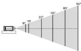
The SX6000/SX4000 is one of the finest, most technically advanced projectors available today. The SX6000/SX4000 enables you to project exceptionally bright, precise images up to 500 inches across (measured diagonally) from your PC or Macintosh computer (desktop or notebook), VCR, document camera, laser disc player, DVD player and even an HD VCR or HD laser disc player.
You can use the projector on a tabletop or cart, you can permanently mount it on a ceiling*, or you can use the projector to project images from behind the screen. The remote control can be used in a wired or wireless configuration.
Features you'll enjoy :
• A high-performance 1.0 KW Xenon lamp that delivers 5000 ANSI lumens (High Bright mode: SX6000) / 3,500 ANSI lumens (Variable mode at max: SX4000) with a lamp life of 1500 hours.
- NEC's unique DLP™ based light engine offers true color reproduction.
- The SX6000/SX4000 can accommodate any picture size from 80 to 500 inches (measured diagonally).
- The SX6000/SX4000 projects images with uniform brightness while colors remain true to their original source.
- The projector can be double or even triple stacked without an external frame, producing bright images of 10,000 or 15,000 ANSI lumens (SX6000) / 7,000 or 10,500 ANSI lumens (SX4000) in addition, double or triple stacking offers built-in redundancy.
- An image can be projected from in front or behind a screen, and the projector can even be installed on the ceiling*.
• Supports RGB digital. HDTV and DVD signals as well as most IBM VGA, S-VGA, XGA, SXGA. UXGA (scaling), Macintosh or any other RGB signals within a horizontal frequency range or 15 to 107 kHz and a vertical frequency range of 24 to 105 Hz. This includes NTSC3.58, PAL, PAL60, SECAM, NTSC4.43, Y/C and 1080i, 720P and 480P HDTV standard video signals.
• Built-in telecine detection enables 3:2 pull-down correction with no external processing necessary, eliminating jitter and artifacts to allow for original film source motion quality.
- A newly designed menu system provides for easy setup and operation of the projector.
- The remote control can be used wired or wireless
Getting Started
The fastest way to get started is to take your time and do everything right the first time. Taking a few minutes now to review the manual may save you hours later on. At the beginning of each section of the manual you'll find an overview. If the section doesn't apply, you can skip it.
What's In The Box?
Make sure your box contains everything listed. If any pieces are missing, contact your dealer. Please save the original box and packing materials if you ever need to ship the projector.
- SX6000/SX4000 Projector
- Remote Control with Remote Cable (wireless/wired).
• DVI-D Cable (SX6000 only)
• Power Cable (for North America and for Europe)
• Two AAA Batteries - User Manual
- CompactFlash Memory Card (8MB) with Adapter
1. Part Names and Functions

* To turn on the main power to the projector, press the switch to the ON position (I) and the POWER indicator on the rear panel will turn amber in color.
Press to the OFF position (0) to turn the main power off.
NOTE: When turning off the main power, first return the projector to the standby condition by pressino the POWER OFF button on the remote control or the POWER
Controls
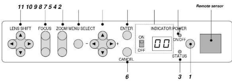
1. Power Button
Press to turn the projector on when the projector is in the standby condition (Main Power switch must be on and the POWER indicator lit amber). Press and hold for 2 seconds to turn off the projector.
2. Power Indicator
When this indicator is green, the projector is on; when the indicator is amber, it is in standby mode.
NOTE: After the projector is turned off, the indicator -- flashes for three minutes to show that the cooling fan is working.
Do not turn off the main power during that time. After “--” stops flashing, the POWER indicator will change to a steady amber glow and the projector will be in the stand-by mode.
3. Status Indicator
6. Cancel Button
Press this button to exit the menu. Press this button to return the adjustments to the last condition while you are in the adjustment or setting menu.
7. Select (Up/Down/Left/Right) Button
Up/Down: Use these buttons to select the menu of the item you wish to adjust.
Left/Right: Use these buttons to change the level of a selected menu item.
8. Menu Button
Displays the main menu for operation.
9. Zoom Button
- ... the loss in and one
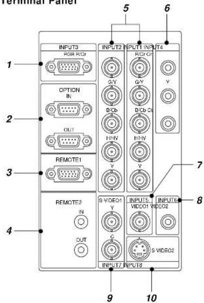
Terminal Panel
-
INPUT 3 RGB Connector (Mini D-Sub 15 pin) Connect your PC or other analog RGB equipment such as a high-definition document camera.
-
Option Connector (MInl D-Sub 9 pin) For system expansion such as PC-control.
IN .... connect to the external equipment such as PC. OUT .... for daisy-chaining multiple projectors and operating them with the same external equipment. To do so, connect to a second projector's IN terminal to relay the input at the IN terminal of the first projector until all the projectors are connected.
-
REMOTE 1 Connector (Mini D-Sub 15 pin) This terminal allows external control of the projector from either the Switcher or from an external control. When the Switcher is used, connect to the REMOTE 1 terminal on the back of the Switcher. NOTE: This projector is compatible with the ISS-6020 Switcher.
-
REMOTE 2 Jacks
IN.... wired remote control input. OUT.... for daisy-chaining multiple projectors and operating them with the same remote control. To do so, connect to a second projector's IN terminal to relay the input at the IN terminal of the first projector until all the projectors are connected.
- INPUT 1 and INPUT 2 Terminals (BNC) Connect R.G,B,H (Horizontal sync) and V (Vertical sync) outputs of the external equipment such as the Switcher. If using a component with a combined sync (SYNC) output, connect it to the H/V terminal. Also connect component video outputs (Y/Cb/Cr) of the external equipment such as DVD player.
NOTE: The INPUT 2 terminal does not support SW1 Level and SW2 Level modes for the ISS-6020 switcher.
-
INPUT 4 Cr/Y/Cb Terminal (RCA) Connect component video outputs (Y,Cb,Cr / Y,Pb,Pr) of the external equipment such as DVD player. NOTE: This terminal accepts component signal only.
-
INPUT 5 VIDEO 1 Terminal (BNC) Connect to the BNC video output of the external equipment such as a VCR or laser disk player.
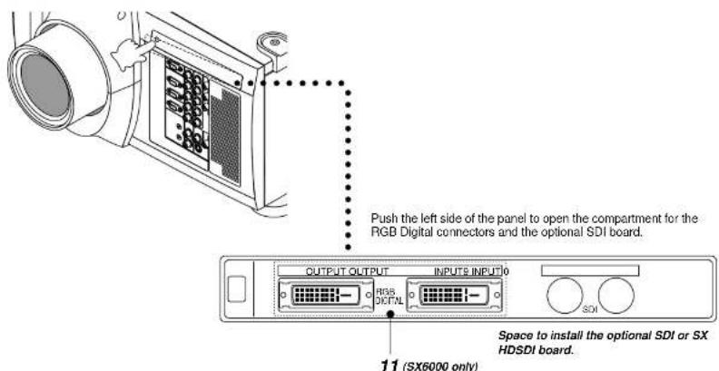
- RGB Digital Input/Output Connectors (DVI-D 24 pin)
These connectors are used for double or triple stacking.
Use the supplied DVI-D cable to connect the OUTPUT terminal of the first projector to the second projector's INPUT until all the projectors are connected.
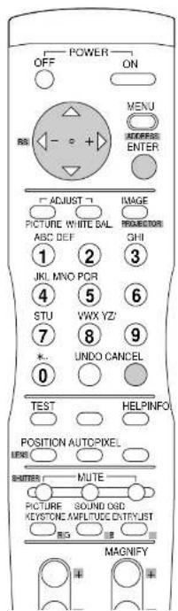
Remote Control
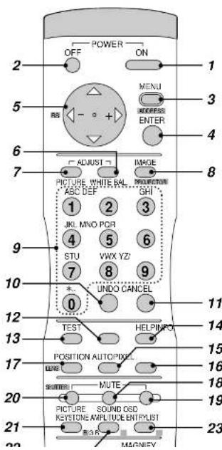
4 ENTER
Executes the menu selection and activates items selected from the menu. When the slidebar or dialog box is displayed: Pressing this button confirms adjustments/setting and returns to the previous menu display.
5 SELECT (Up/Down/Left/Right)
When pressed together, the CTL and ▶buttons work as a Back Space key in the entry screen. Pressing and holding CTL, then this button moves the menu, slidebar or dialog box.
6 ADJUST WHITE BAL
Press to display the Color adjustment screen. Pressing this button sequentially selects "Color Temperature" - "White Balance - Brightness" - "White Balance - Contrast" - "Signal Level" - "Ref. White Bal" - "Switcher-Gain".
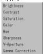
7 ADJUST PICTURE
Press to display the Picture adjustment screen. Pressing this button sequentially selects "Brightness" → "Contrast" → "Saturation" → "Color" → "Hue" → "Sharpness" → "V-Aperture" → "Gamma Correction".
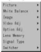
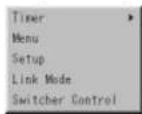
8 IMAGE/PROJECTOR
Press to display the Image Option screen. Pressing this button sequentially selects "Pixel Adjust" → "Position" → "Aspect Ratio" → "Resolution" → "Overscan" → "Video Filter" → "Blanking". While pressing and holding CTL, pressing this button rotates "On/OFF Timer" → "Sleep Timer" → "Menu" → "Setup" → "Link Mode" → "Switcher Control".
9 INPUT
Use to select an input, to name a signal, or to enter a passcode during input registration. 1--INPUT 1 for RGBHV/Y, Cb/Pb, Cr/Pr 2--INPUT 2 for RGBHV/Y, Cb/Pb, Cr/Pr 3--INPUT 3 for RGB 4--INPUT 4 for Y, Cb/Pb, Cr/Pr 5--INPUT 5 for VIDEO 1 6--INPUT 6 for VIDEO 2 7--INPUT 7 for S-VIDEO 1 8--INPUT 8 for S-VIDEO 2 9--INPUT 9 for RGB DIGITAL input 0--INPUT 0 for SDI input on the optional SDI board
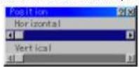
17 POSITION
Press to display the Blanking screen; press again to display the Position screen.
While pressing and holding CTL, pressing this button displays the Lens Shift adjustment screen.
18 MUTE SOUND
(available only when using with the ISS -6020 or IPS4000) Tums off the sound for a short period of time. Press again to restore the sound.
19 MUTE OSD
Press to turn off the on-screen display. Press again to restore the on-screen display.
NOTE: You can also turn off the on-screen display by pressing and holding CTL and then pressing MUTE OSD; doing this again restores it. In this case any adjustment will still change the projector's memory settings. This mode is available even when an input is switched to another or the power is turned off using the POWER OFF button on the remote control.
20 MUTE PICTURE
Press to turn off the picture for a short period of time. Press again to restore the picture. Pressing and holding CTL, then pressing this button shuts off the light completely.
21 KEYSTONE (R)
Press to display the Keystone Correction screen.
22 AMPLITUDE (G)
Service personnel only.
23 ENTRY LIST (B)
Press to display the Entry List screen.
24 FOCUS (+/-)
While pressing and holding CTL, pressing this button allows you to adjust the lens focus.
25 MAGNIFY/ZOOM (+/-)
Magnify the size of a target portion. While pressing and holding CTL, pressing this button allows you to zoom the lens in and out.
of CTI
Remote Control Precautions
- Use the remote control within a distance of about 7m (23feet) and at an angle of 30^ above, below, to the left and to the right of the remote control sensor located at the front of the main unit.
- The remote control system may not function when direct sunlight or strong illumination strikes the remote control sensor of the main unit, or when there is an obstacle in the path.
- When remote control buttons are pressed and held, main unit function keys may not operate.
- Do not subject to strong shock.
- Do not allow water or other liquid to splash on the remote control. If the remote control gets wet, wipe it dry immediately.
- Avoid exposure to heat and steam.
- Remove the batteries from the remote control when the remote control is not going to be used for a long period.
You cannot operate the projector using the remote control if:
• the remote ID is not set to [00].
- the remote ID is not the same as the projector ID. See page E-23 for setting remote ID and page E-39 for setting projector ID.
Remote Control Battery Installation
Installing the Remote Control Batteries
When it comes time to replace the batteries, two "AAA" type will be required.
- Press and open the cover.
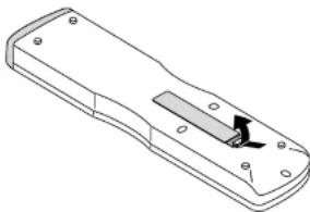
natural_image
Technical line drawing of a remote control casing with a slot and mounting holes (no text or symbols)- Align and insert the batteries according to the (+) and (-) indications
2. INSTALLATION
This section describes how to set up your projector and how to connect video and audio sources.
Setting Up Your Projector
Your Projector is simple to set up and use. But before you get started, you must first:
-
Determine the image size
-
Set up a screen or select a non-glossy white wall onto which you can project your image.
- Install the optional lens to the projector.
NOTE: The lens must be installed by service personnel only.
- Connect the supplied power cable.
- Set up the projector.
- Connect a PC, VCR, DVD player, or other equipment.
- Make settings or adjustments on the projector.
Screen Size and Projection Distance
Applicable lens and throw distance/ List of screen sizes

Formulas: Screen Width H (5:4) (m) = Screen Height V x 5/4 x 0.0254 Screen Height V (5:4) (m) = Screen Width H x 4/5 x 0.0254 Screen Diagonal (5:4) (m) = Screen Height V x 6.4/4 x 0.0254 Screen Width H (5:4) (inch) = Screen Height V x 5/4 Screen Height V (5:4) (inch) = Screen Width H x 4/5 Screen Diagonal (5:4) (inch) = Screen Height V x 6.4/4
Throw Distance
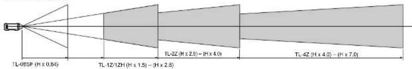
NOTE: Image has 5:4 aspect ratio. Take this into account when specifying a screen.
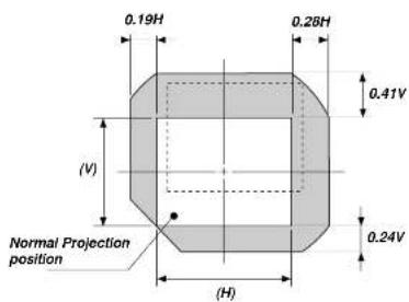
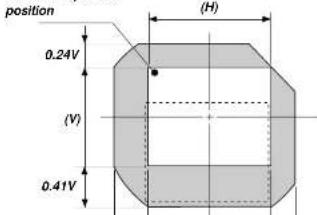
Lens Shift Adjustable Range
Lens Shift Adjustable Range for Desktop and Ceiling Mount Application
The diagram below shows the location of the image position in the lens. The lens can be shifted within the shaded area as shown using the normal projection position as a starting point.
Maximum Possible Range for TL-1Z/1ZH, TL-2Z and TL-4Z
Parenthesized values for the ceiling mount application
Up: 0.41 V (0.24 V) Right: 0.28 H (0.19 H)
Down: 0.24 V (0.41 V) Left: 0.19 H (0.28 H)
(H: width of projected image. V: height of projected image)
Desktop/ Front
Vertical

Ceiling/ Front

Normal Projection
Example for Stack

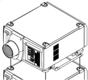
Moving The Projector
Always carry your projector by the handle. Ensure that the power cord and any other cables connecting to video sources are disconnected before moving the projector. When moving the projector or when it is not in use, cover the lens with the lens cap.

natural_image
Technical line drawing of a device with labeled components and connectors (no text or symbols)Pulling Out the Handles
Pull out the handle until it clicks into place.

Selecting A Location
The further your projector is from the screen or wall, the larger the image. The minimum size the image can be projected is 80" (2 m) measured diagonally. The largest the image can be is 500" (12.7 m).
WARNING
- Only use your projector on a solid, level surface. If the projector falls to the ground, you can be injured and the projector severely damaged.
- Do not use the projector where temperatures vary greatly. The projector must be used at temperatures between 40 degrees F (5 degree C) and 95 degrees F (35 degree C).
- Do not expose the projector to moisture, dust, or smoke. This will degrade the screen image.
- Ensure that you have adequate ventilation around your projector for proper heat dissipation. Do not cover the vents on the projector cabinet.
3. BASIC OPERATION
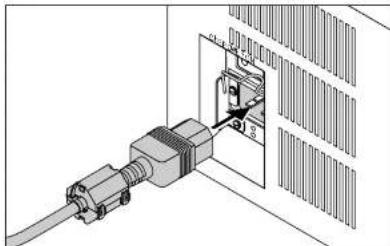
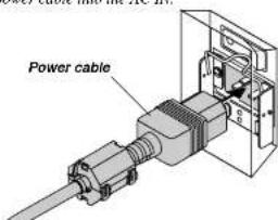
Connecting the Power Cable and Turn on the Projector
Before you turn on your projector, ensure that the computer or video source is turned on and that your lens cap is removed.
- Connect the supplied power cable to the projector.
Plug the supplied power cable into the AC outlet.
natural_image
Technical diagram of an electrical connector with a cable and internal components (no text or symbols)- Turn On The Projector
The main power switch is on the rear panel of the projector. By turning this switch on, the projector will go into its standby mode and the POWER indicator will glow orange. Only after you press the 'POWER ON' button on the remote control or projector cabinet will the POWER indicator turn to green and the projector will fully turn on.
- Turn Off The Projector
First press the POWER OFF button on the remote control or the projector cabinet for a minimum of two seconds. Allow the fan to cool the projector for three minutes.
This will extend the life of the lamp. After the cooling fan stops working, the POWER indicator will change to a steady orange glow and the projector will be in the stand-by mode. Then turn off the main power switch on the rear panel. The POWER indicator will
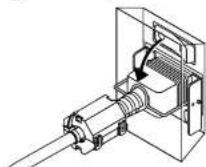
Using the Power Cable Stopper
The Power cable wire stopper is provided on the projector so that the cable cannot be accidentally unplugged from the AC IN.
- Lift up the wire stopper.
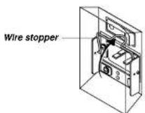
- Plug the power cable into the AC IN.
- Lift down the wire stopper to hold the power cable.
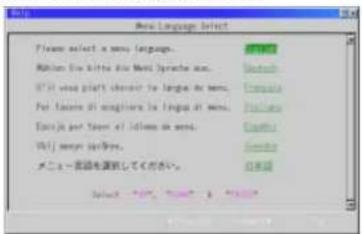
About Startup Screen
(Menu Language Select screen)
When you first turn on the projector, you will get the Startup screen.
This screen gives you the opportunity to select one of the seven menu languages: English, German,
French. Italian, Spanish, Swedish and Japanese.
To select a menu language, follow these steps:
- Use the Select ▲ or ▼ button to select one of the seven languages for the menu.
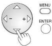
- Press the Enter button to execute the selection.


- The Basic/Custom menu will be displayed in the language you have selected.
Set up the projector
-
Turn on the projector
-
Select your type of projection:
Desktop front, ceiling rear, desktop rear, and ceiling front.
- Display the test pattern by pressing the TEST button on the remote control or using the menu.

- Adjust the image position and the image size.
(1) Press and hold the CTL button and press the POSITION button to display the Lens Shift adjustment screen.
Use the Select button on the remote control or the LENS SHIFT button on
the projector cabinet to move the image horizontally and vertically.
To close the the Lens Shift adjustment screen, press the CANCEL button.
See page E-9 for "Lens Shift Adjustable Range"
POSITION


(2) Press and hold the CTL and press the ZOOM + or - button to adjust the image size. You can also adjust the image size by using the ZOOM + or - button on the projector cabinet.
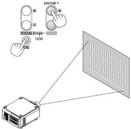
(3) Press and hold the CTL button and press the FOCUS + or - button to obtain the best focus. You can also adjust the focus by using the FOCUS + or - button on the projector cabinet.

Keystone
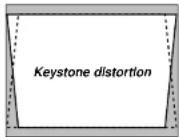
Keystone is the distortion of a projected image that usually creates a wider top than bottom. Aiming a projector upward on a wall rather than straight at a wall creates this distortion. Use the ◀ or ▶ buttons on the slide bar to correct this keystone (trapezoidal) distortion.
NOTE: The kystone feature is not available when the test pattern or the blue back is displayed.
NOTE: With the projector aimed directly at the screen the maximum keystone angle that can be corrected is +/- 7.5 degrees.
Setting up for Double or Triple Stacking in Link Mode
natural_image
Technical line drawing of a mechanical device with no visible text or symbols2) Hookup
2-1. Use the supplied DVI-D cable to connect the RGB DIGITAL output of the master projector to the RGB DIGITAL input (INPUT9) of the slave projector (the second and third stack) until all the projectors are connected.
2-2. Next, using a commercially available. bi-directional RS-232C cable connect the OPTION OUT terminal of the master projector to the OPTION IN terminal of the slave projector(s) until all the projectors are connected.
2-3. Turn all the projectors on and roughly make some optical adjustments to each projector.
3) Adjusting and registering signals to be projected in Link mode and stack application.
Signal Data Preparation
3-1. Create data for the master projector and copy data to the slave projector.
3-1-1. Choose one projector as the master.
3-1-2. Turn the master projector on.
3-1-3. Display all desired input signals, make adjustment to each signal, then save all adjustments on the master projector. (Adjustments will be saved automatically.)
3-1-4. Turn the master projector off (standby mode).
3-1-5. Store all the adjustments on a PC card from the master projector.
3-1-5-1. Open the PC Card slot cover to access the PC card slot. Insert a PC card into this slot.
NOTE: DO NOT TURN OFF THE POWER while the PC Card Access indicator is flashing. Doing so will cause damage to the data of the projector system.
NOTE: Back up your data if you use the supplied CompactFlash card to copy the data from the master projector to the slave projector. The supplied
3-1-6-3. Remove the PC card from the slave projector.
NOTE: If you select the RGB1 input on the master projector, you must select the same input on the slave projector and the RGB2 on the master projector and the slave projector.
NOTE: After adjusting and registering signals as mentioned above, you must change the input to RGB on the Entry Edit Command window for Link Mode. See "Entry List Edit" on page E-31 for changing to RGB source.
3-1-6-4. Display the desired source.
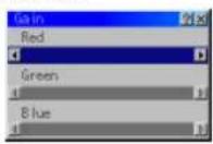
4) Display the internal crosshatch test pattern.
NOTE: Use a different single color for each projector.
Example:
Turn on Green of one projector (master), then Red of the other (slave).
5) Adjusting the lens shift, zoom and focus to clearly display all projected patterns.
5-1. Adjust the Lens Shift using the LENS SHIFT button on the projector cabinet. You can also adjust the Lens Shift by pressing and holding CTL and pressing the POSITION button on the remote control. For Lens Shift Adjustable Range, see page E-9.
5-2. Zoom the lens in and out by using the ZOOM button on the projector cabinet or the remote control.
5-3. Adjust the lens focus by using the FOCUS button on the projector cabinet or the remote control.
NOTE: If the physical (vertical) alignment of the projector is not correct, adjust the height of the feet. If there is any keystone distortion, use Keystone adjustment to correct and save the settings on each projector. See page E-14 and E-35 for Keystone correction. This completes set-up and adjustments. An image is projected from the master projector. See page E-39 for Link mode.
6) Link Mode Setting
6-1 Assign a unique Projector ID for each projector.
6-4 Project a source image from all projectors
6-4-1. Display any signal onto the screen.
6-4-2. Check to see if the images on the master projector are displayed in synchronization with the ones on the other slave projector while the projectors are in link mode.
NOTE: Registering signals is not possible in the Link mode. To register a signal, first set 'Link Mode' to "Standalone" on the menu and then repeat the above steps from 3. If you select an unregistered signal, the master projector displays the image, but the slave projector doesn't. To view the information on the currently displayed signal, select [Help] → [Source Information].
6-5 Make adjustments to the slave projector.
NOTE: See "List of Menu Items Available on Link Mode" on page E-45 for more information.
6-5-1. Temporarily, change the master projector from Master to Standalone.
Make sure that the slave projectors are still in Slave mode.
6-5-2. Display a source you want to adjust from the master projector.
6-5-3. On the Slave Projector select the same signal From the Entry List (same No.) as that of the master projector. Display it from the slave projector.
6-5-4. Make Picture adjustment such as brightness, contrast, or color temperature.
6-5-5. Change the master projector from Standalone to Master to activate the Link Mode
6-6 This completes the Link Mode adjustment procedure.
NOTE: When the Link mode is enabled, be sure to turn on the master projector first and then the slave projector.
If you fail to do this, the slave projector will not work correctly. Once you have turned on the master projector, the slave projector(s) will automatically be turned on.
NOTE: In the Link mode the Lens Memory feature is not available.
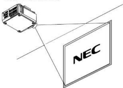
Projector Orientation
An image can be projected from in front or behind a screen, and the projector can be installed on the ceiling*.
Ceiling Front Projection
Use [Projector Options] → [Setup] → [Page 1] → [Orientation] to select "Ceiling Front". (See page E-38.)
Ceiling Rear Projection
Use [Projector Options] · [Setup] · [Page 1] · [Orientation] to select "Ceiling Rear". (See page E-38.)

WARNING
• Installing your projector on the ceiling must be done by a qualified technician. Contact your NEC dealer for more information.
* Do not attempt to install the projector yourself.
- Only use your projector on a solid, level surface. If the projector falls to the ground, you can be injured and the projector severely damaged.
- Do not use the projector where temperatures vary greatly. The projector must be used at temperatures between 40°F (5°C) and 95°F (35°C).
- Do not expose the projector to moisture, dust, or smoke. This will harm the screen image.
- Ensure that you have adequate ventilation around your projector so heat can dissipate. Do not cover the vents on the projector.
4. CONNECTIONS
When used in standalone operation
Connecting Your PC Or Macintosh Computer
Connecting your PC or Macintosh computer to SX6000/SX4000 Projector will enable you to project your computer's screen image for an impressive presentation.
To connect to a PC or Macintosh :
1. Turn off the power to your projector and computer.
2. Use a signal cable (not provided) to connect your PC or Macintosh computer to the projector.
3. Turn on the projector and the computer.
4. If the projector goes blank after a period of inactivity, it may be caused by a screen saver installed on the computer.
Connecting Your Document Camera
You can connect the projector to a document camera. To do so, simply: 1. Turn off the power to your projector and document camera.
2. Use a standard video cable to connect your document camera to the Video input on your projector. Or connect to the INPUT3 (RGB) on your projector.
3. Turn on the projector and the document camera.
NOTE: Refer to your document camera's owner's manual for more information about your camera's video output requirements.
Connecting Your VCR Or Laser Disc Player
Use common RCA cables (not provided) to connect your VCR or laser disc player to your SX6000/SX4000 Projector. To make these connections, simply:
- Turn off the power to your projector and VCR or laser disc player.
- Connect one end of your RCA cable to the video output connector on the back of your VCR or laser disc player, connect the other end to the Video input on your projector. Use standard RCA audio patch cords to connect the audio from your VCR or laser disc player to your projector (if your VCR or laser disc player has this capability). Be careful to keep your right and left channel connections correct for stereo sound.
- Turn on the projector and the VCR or laser disc player.
NOTE: Refer to your VCR or laser disc player owner's manual for more information about your equipment's video output requirements.

natural_image
Diagram showing a robotic arm interacting with a computer and a server (no text or symbols present)When Used with One Switcher (ISS-6020/ISS-6020G)
Up to 10 input signals can be accepted when the projector is connected to one Switcher. Using the projector with the Switcher allows easy adjustment and signal selection.
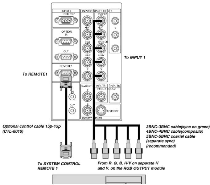
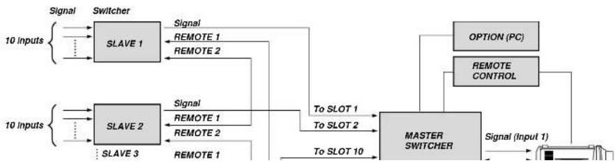
When Used with Two or More Switchers (100 Inputs)
Up to 100 inputs can be accepted using the NEC ISS-6020 Switcher.
How to make connections:
-
Connect the REMOTE 1 terminal of the master Switcher to the REMOTE 1 of the projector using the optional control cable (15p-15p/CTL-6010).
-
Next connect the REMOTE 2 terminal of the master Switcher to the REMOTE 1 terminal of the first slave Switcher using the same optional control cable as mentioned above. Third, connect the REMOTE 2 terminal of the first slave to the REMOTE 1 of the second slave, and the REMOTE 2 terminal of the second slave to the REMOTE 1 terminal of the third slave (— and the REMOTE 2 of the ninth slave to the REMOTE 1 of the tenth slave). Connect all the Switchers with optional control cables.
NOTE:
- Be sure to set all the slide switches (S8603) of the Switcher to RS-422 positions. Set the one on the last slave Switcher to the appropriate position to match the connected equipment such as a personal computer. (RS-422/RS-232C for PC control of projector)
- Set the DIP switch S8601 of the Switcher.
flowchart
graph TD
    A["10 Inputs"] --> B["SLAVE 1"]
    A --> C["SLAVE 2"]
    A --> D["SLAVE 3"]
    B --> E["Signal"]
    B --> F["Signal"]
    B --> G["Signal"]
    C --> H["Signal"]
    C --> I["Signal"]
    C --> J["Signal"]
    D --> K["SLAVE 1"]
    D --> L["SLAVE 2"]
    D --> M["SLAVE 3"]
    E --> N["REMOTE 1"]
    E --> O["REMOTE 2"]
    F --> P["REMOTE 1"]
    F --> Q["REMOTE 2"]
    G --> R["REMOTE 1"]
    G --> S["REMOTE 2"]
    H --> T["To SLOT 1"]
    I --> U["To SLOT 2"]
    J --> V["To SLOT 10"]
    K --> W["MASTER SWITCHER"]
    L --> W
    M --> W
    N --> W
    O --> W
    P --> W
    Q --> W
    R --> W
    S --> W
    T --> X["OPTION (PC)"]
    U --> Y["REMOTE CONTROL"]
    V --> Z["Signal (Input 1)"]
    W --> AA["Signal (Input 1)"]
Set the DIP switch (S8601) of the Switcher as follows:
NOTE: Slave numbers 1 to 10 must correspond to the master's slot numbers 1 to 10.
| ISS-6020 ISS-6020G | Output to | Setting of S8601 |
| Master | The Projector | 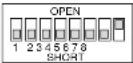 |
| Slave 1 | Slot 1 of the Master |  |
| Slave 2 | Slot 2 of the Master |  |
| Slave 3 | Slot 3 of the Master | 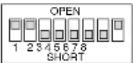 |
| Slave 4 | Slot 4 of the Master |  |
| Slave 5 | Slot 5 of the Master | 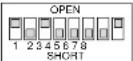 |
| Slave 6 | Slot 6 of the Master | 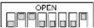 |
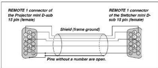
REMOTE 1 Connector

2 3
This connector is used for either connecting the ISS-6020/ISS-6020G Switcher or a third party external control device. When the Switcher is used, connect it with the optional control cable (15-15 pin; 50 ft./16m; CTL-6010) to this connector.
When used with the Switcher.
| Pin No. FUNCTION | |
| 1, 2, 6 and 7 Sending and receiving data when the Switcher is used. | |
| 9 Identifying the Projector | |
| 15 Ground | |
| 3, 8, 11 and 12 Used inside the Projector. Normally set to OPEN. | |
When using with the Switcher ISS-6020/ISS-6020G, connect No. 1,2,6,7,9 and 15 pins of the projector to the same No. pins of the switcher as shown below.
Pin Configuration of Optional CTL-6010 Cable
When used in stand alone operation.
| Pin No. | SHORT/OPEN | FUNCTION | |||
| 14 | SHORTOPEN | External control mode ONExternal control mode OFF | |||
| 5 | SHORTOPEN | POWER ONPOWER OFF | |||
| 10 | SHORTOPEN | PICTURE MUTE ONPICTURE MUTE OFF | |||
| 4,8,12,11 | 11pin | 12pin | 8pin | 4pin | |
| OPEN | OPEN | OPEN | OPEN | RGB 1 (INPUT 1) | |
| OPEN | OPEN | OPEN | SHORT | VIDEO 1 (INPUT 5) | |
| OPEN | OPEN | SHORT | OPEN | S-VIDEO 1 (INPUT 7) | |
| OPEN | OPEN | SHORT | SHORT | COMPONENT (INPUT 4) | |
| OPEN | SHORT | OPEN | OPEN | SDI (INPUT 0) | |
| OPEN | SHORT | OPEN | SHORT | RGB 2 (INPUT 2) | |
| OPEN | SHORT | SHORT | OPEN | VIDEO 2 (INPUT 6) | |
| OPEN | SHORT | SHORT | SHORT | S-VIDEO 2 (INPUT 8) | |
| SHORT | OPEN | OPEN | OPEN | RGB (DIGITAL) (INPUT 9) | |
| SHORT | OPEN | SHORT | OPEN | RGB 3 (INPUT 3) | |
* When the combinations other than specified in the above table are selected, the input will be forcefully switched to RGB 1.
* The term "SHORT" means to connect with pin 15
* When in the external control mode, the POWER, INPUT, PICTURE MUTE and SOUND MUTE buttons on the remote control will not function.
NOTE: Pin 13 is the external remote signal terminal. The projector can be controlled by the same format signal as the supplied remote control from the external controller regardless of setting on Pin 14.
NOTE: When turning off the power to the projector using the external control, do not disconnect the plug from the power outlet. These procedures are to protect your projector and the connected equipment.
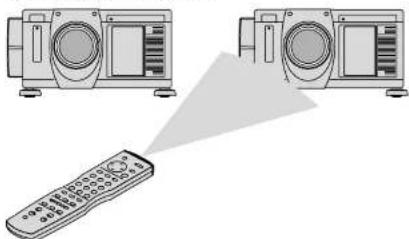
Operating Multiple Projectors with Remote Control
You can operate multiple projectors with the same remote control in wireless operation.
To do so:
-
Select [Menu] → [Projector Options] → [Setup] → [Page 5] → [Projector ID] and assign an ID number to each projector. See also page E-39.
-
On the remote control specify the ID number of the projector to be adjusted. Press and hold the CTL and press MENU (ADDRESS) button to enter the ID number.
You can operate the projector assigned the same ID number as the remote control.
Projector ID=01

Projector ID=02 Projector ID=03
natural_image
Illustration of two radio units connected by a triangular pointer to a remote control (no text or symbols)Remote Address = 03
You can daisy-chain multiple projectors and operate them separately with the same remote control in wired operation.
To do so:
- Use the remote control cable to connect the REMOTE 2 Output of one projector to the REMOTE 2 Input of the next projector until all the projectors are
connected. Only one remote control cable is supplied with each projector.
-
Specify a unique projector ID for each projector.
-
Specify the same remote address as the projector ID to be adjusted.
NOTE: Specifying "None" for projector ID allows you to operate multiple projectors concurrently. However, some projectors may not synchronize to the other projectors.

Using the RGB DIGITAL connectors (SX6000 only)
The Link mode function allows you to adjust or set multiple projectors using the RGB DIGITAL and OPTION connectors.
The DVI DIGITAL input accepts up to the SXGA (1280 x 1024 @75Hz) sigma
NOTE: The Auto Adjust feature does not work for DVI digital signal. When DVI signal is selected and the image position is not corrected, adjust the horizontal and vertical position using the Position screen. See page E-33 for more details.
Connection for Double or Triple Stacking in Link Mode

It is recommended that you use a commercially available distribution amplifier if you use signals higher than SXGA (1280 X 1024@75Hz) in Link mode.
Link Mode
You can daisy-chain up to 16 projectors and operate them separately with the same remote control in wired operation.

5. OPERATION
This section describes how to select a computer or video source, adjust the picture and sound, edit a signal and adjust all other settings and adjustments for proper projector set-up.
General Controls
Before you turn on the projector ensure that the computer or video source is turned on and that the lens cap is removed.
1. Turn On The Projector
Plug the supplied power cable into the AC outlet. The main power switch is on the rear panel of the projector. By turning this switch on, the projector will go into its standby mode and the POWER indicator will glow orange. Only after you press the 'POWER ON' button on the remote control or projector cabinet will the POWER indicator turn to green and the projector will fully turn on.
2. Select The Computer Or Video Source
Press the INPUT button on the remote control to select the desired source. Or press the MENU button on the remote control and use the Source Select to select your video source: Video, S-Video, RGB, Y/Cr/Cb, RGB Digital (SX6000 only) or SDI.
3. Adjust The Image
Press the ADJUST PICTURE button or the ADJUST WHITE BAL on the remote control or select the [Menu] → [Adjust (Source)] to adjust the picture.
4. Turn Off The Projector
First press the POWER OFF button on the remote control or the projector cabinet. Allow the fan to cool the projector for three minutes. This will extend the life of the lamp. After the cooling fan stops working, the POWER indicator will change to a steady orange glow and the projector will be in the stand-by mode. Then turn off the main power switch on the rear panel. The POWER indicator will go out. If you desire to move the projector then unplug the power cable.
IMPORTANT:
- The projector should be unplugged if it will not be used for an extended period.
- If you want to turn off the image briefly (five minutes or less). press the MUTE PICTURE button instead of turning the projector off and on.
• The projector will display a black blue image or logo if no input signal
NOTE: The change is stored automatically when any one of the following procedures is performed:
* The on-screen dissapears.
* The projector goes into standby.
* One input is switched to another.
- Repeat steps 2-5 to adjust an additional item, or press the CANCEL button on your remote control to quit.
Shutter mechanism
The projector is equipped with "Shutter" feature, which allows the user to shut off the light completely on the screen. To use the shutter function, hold down the CTL button, and press the MUTE PICTURE button on the remote control.
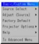
Customizing Basic/Custom Menu
The Basic/Custom menu can be customized to meet your requirements. Selecting a menu item from the "Basic/Custom Menu Edit" list, allows you to custom tailor the menu items to your needs.
- Select "Basic/Custom Menu Edit" to display the "Basic/Custom Menu Edit" screen.
- Use the ▲ or ▼ button to highlight your selection and press the Enter button to place a check mark next to an option. This action enables that feature.
Press the Enter button again to clear the check box.

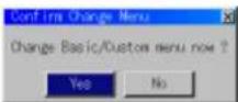
NOTE: If the "Advanced Menu" Item has been selected on the Menu mode, you get the "Confirmation Change Menu" upon completion of "Basic/Custom Menu" editing. In this case, selecting "Yes" then "Enter" will close all the menus and apply the changes from the Advanced menu to the Basic/Custom Menu. If you select "No" then "Enter" functions, then all menu items will return to the Advanced menu, but your changes will still be available within the "Basic/Custom Menu" selection. To display the previously tailored Basic/Custom Menu, select "Basic/Custom Menu" from the "Menu Mode".
An item "To Advanced Menu" will be added to the bottom of the Basic Custom Menu. Selecting this item and pressing the "Enter" button will display the "Advanced Menu" features.
A List of Direct Key Combinations
| CTL+ INPUT (1-10) Switches to any selected signal found in the Entry List.To enable this combination, you must first assign specific remote keys for direct input selection in the Entry Edit window. | |
| CTL+ ENTER (While displaying Entry list) Displays the Entry Edit Command window. | |
| CTL+ MUTE PICTURE(SHUTTER) Blocks all Projector Light Output. | |
| CTL+CANCEL Returns to the previous menu without closing the slidebar or dialog. | |
| CTL+ UNDO Clears all menus or adjustment'setting screens. All adjustments are saved automatically. | |
| CTL+ ◀/▶/▲/▼ | Moves the slidebar or dialog box horizontally or vertically. |
| While using zoom on remote control: Displays the magnifying glass icon. | |
| CTL+ ◀ (BS) Deletes one letter or numeral in the entry screen. | |
| CTL+MUTE (OSD) Tums off the on-screen display forcefully. | |
| INPUT(1-10) in SW Level mode Displays the Select switcher Input Slot window. | |
| NOTE: This feature is available for SW 2 Level mode only.When the SW 1 Level mode is selected, pressing INPUT key switches to the corresponding slot without displaying the Select Slot window. | |
| CTL+ MENU (ADDRESS) Displays the remote ID entry window. | |
| CTL+ IMAGE (PROJECTOR) Sequentially selects the Projector Options sub menu. | |
| CTL+ POSITION (LENS) | Displays the Lens Shift control window. |
| CTL+ KEYSTONE {R} | Turns on red. Available only when the projector is in the test pattern mode. |
| CTL+ AMPLITUDE {G} | Turns on green. Available only when the projector is in the test pattern mode. |
| CTL+ ENTRY LIST {B} | Turns on blue. Available only when the projector is in the test pattern mode. |
| CTL+ MAGNIFY (ZOOM) | Zooms the lens in and out |
| CTL+ (FOCUS) | Adjusts the lens focus. |
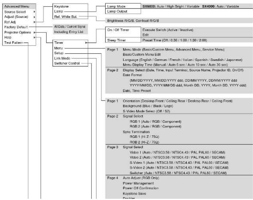
Menu Tree

flowchart
graph TD
    A["Advanced Menu"] --> B["Source Select"]
    A --> C["Adjust (Source)"]
    A --> D["Hot Adj"]
    A --> E["Factory Default"]
    A --> F["Projector Options"]
    A --> G["Help"]
    A --> H["Test Pattern"]
    I["Stand alone"] --> J["RGB1"]
    I --> K["RGB2"]
    I --> L["RGB3"]
    I --> M["Component (YCbCr)"]
    I --> N["Video1"]
    I --> O["Video2"]
    I --> P["S-Video1"]
    I --> Q["S-Video2"]
    I --> R["RGB (DIGITAL)"]
    I --> S["SDI"]
    I --> T["Entry List"]
    U["Picture"] --> V["White Balanoo"]
    U --> W["Image"]
    U --> X["Video Adj"]
    U --> Y["Option Adj"]
    U --> Z["Lens Memory"]
    U --> AA["Signal Typo"]
    U --> AB["Switcher"]
    AC["Brightness"] --> AD["Contrast"]
    AE["Saluration"] --> AF["Color"]
    AE --> AG["Hue"]
    AE --> AH["Sharpness"]
    AE --> AI["V-Aperture"]
    AE --> AJ["Gamma Correction"]
    AK["Color Temperature"] --> AL["Brightness"]
    AK --> AM["Contrast"]
    AK --> AN["Signal Level"]
    AO["Pixel Adjust"] --> AP["Position"]
    AO --> AQ["Aspect Ratio"]
    AO --> AR["Resolution"]
    AO --> AS["Overscan"]
    AO --> AT["Video Filter"]
    AO --> AU["Blanking"]
    AO --> AV["On/Off Top/Bottom"]
    AW["Noise Reduction"] --> AX["Luminance Off/Low/Medium/High\nChrominance Off/Low/Medium/High"] --> AX
    AY["Y/C Delay"] --> AZ["Select Color Matrix HDTV/SDTV\nDelect Color Matrix Type B-YR-Y, UV, CbVCr\nPbPr, IVX"] --> AX
    BA["Tolocine"] --> BB["Auto/Off"] --> BC["Still/Adaptive"] --> BD["YTH Adjustment"]
flowchart
graph TD
    A["Advanced Menu"] --> B["Source Select"]
    A --> C["Adjust (Source)"]
    A --> D["Rot Adj"]
    A --> E["Factory Default"]
    A --> F["Projector Options"]
    A --> G["Help"]
    A --> H["Test Pattern"]

    I["Keystone"] --> J["Lamp Mode"]
    I --> K["Lamp Output"]

    L["Timer"] --> M["Menu Setup"]
    L --> N["Link Mode Switcher Control"]

    O["Al Data / Current Sign Including Entry List"] --> P["AI Data / Current Sign Including Entry List"]

    Q["Lock Mode"] --> R["Lamp Mode"]
    Q --> S["Lamp Output"]

    T["Brightness R/G/B Contrast R/G/B"] --> U["On/Off Timer"]
    T --> V["Execute Switch (Active/Inactive)"]
    T --> W["Edit"]

    X["Sleep Timer"] --> Y["Preset Time (Off/0.30/1.00/1.30/2.00)"]

    Z["Page 1 Menu Mode (Basic/Custom Menu, Advanced Menu, Service Menu) Basic/Custom Menu Edit Language (English / German / French / Italian / Spanish / Swedish / Japanese) Menu Display Time (Manual / Auto 5 sec / Auto 10 sec / Auto 30 sec)"] --> AA["Page 2 Display Select (Date, Time, Input Terminal), Source Name, Projector ID, On/Off"] Date Format (MM/DD/YYYY, MM/DD/YYYY ddd, DD/MM/YYYY, DD/MM/YYYY ddd, YYYY/MM/DD, YYYY/MM/DD ddd, Month DD, YYYY, Month DD, YYYY ddd) Date, Timo Proset]

    AB["Page 1 Orientation (Desktop Front / Ceiling Rear / Desktop Rear / Ceiling Front) Background (Blue / Black / Logo) S-Video Mode Select (Off/S2)"] --> AC["Page 2 Signal Select RGB 1 (Auto / RGB / Component) RGB 2 (Auto / RGB / Component) Sync Termination RGB 1 (Hi-Z/75Q) RGB 2 (Hi-Z/75Q)"]

    AD["Page 3 Signal Select Video 1 (Auto / NTSC3.58 / NTSC4.43 / PAL PAL60 / SECAM) Video 2 (Auto / NTSC3.58 / NTSC4.43 / PAL PAL60 / SECAM) S-Video 1 (Auto / NTSC3.58 / NTSC4.43 / PAL PAL60 / SECAM) S-Video 2 (Auto / NTSC3.58 / NTSC4.43 / PAL PAL60 / SECAM) Switcher (Auto / NTSC3.58 / NTSC4.43 / PAL PAL60 / SECAM)"]

    AE["Page 4 Auto Adjust (RGB Only) Power Management Power Off Confirmation Keystone Save Power"] --> AF["End"]
Menu Elements


Menu Descriptions & Functions Source Select
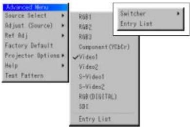
Enables you to select a video source such as a VCR, DVD player, laser disc player, computer or document camera depending on what is connected to your inputs.
Press the up/down buttons on your remote control or the projector cabinet to highlight the menu for the item you want to adjust.
^A RGB1.2.3
* Component (YCbCr)
* Video 1.2
* S-Video 1.2
* RGB (Digital)
A SOI
Swicher

You can select the slot number from 1 to 10 of the Switcher(s) ISS-6020.
When using with a single Switcher ISS-6020:

Entry List
Displays the list of the entry signals. Use the ▲▼ buttons on your remote control or the projector cabinet to select the signal and press the ENTER button on the remote control or the projector cabinet to project the image of the selected source.

Entry Edit Command
You can edit the signal on the entry list.
To do so
- While pressing and holding CTL, press ENTER on the remote control to display the Entry Edit Command window.
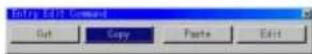
* Cut Enables you to remove a selected signal from the list and place it on the "clipboard" in the projector.
* Copy Enables you to copy a selected signal from the list and place it on the "clipboard" in the projector.
* Paste Enables you to paste the signal placed on the "clipboard" to any other line of the list. To do this, select "Paste" and then select the line number you want to paste to. Last press ENTER.
* Edit Enables you to change source name or assign the direct key.
• The following buttons are not available for the currently projecting signals:
1) The Cut and Paste buttons on the Entry Edit Command screen
2) The Input Terminal button on the Entry Edit screen

Select "List" and press ENTER to display the direct Key assignment list.
Select "OK" and press ENTER to close the window.
To close the List window, press CANCEL on the remote.

Adjust (Source)
Picture
Brightness
Adjusts the brightness level or the back raster intensity.
Contrast
Adjusts the intensity of the image according to the incoming signal.
Saturation
Adjust saturation at the white peak.
White Balance

Color Temperature
This feature adjusts the color temperature using the slide bar. Move the slide bar to the right to increase the color temperature for a bluish image; to the left to decrease it for a reddish image,
Brightness
Brightness for each color (RGB) is used to adjust the black level of the screen.
Contrast
Contrast for each color (RGB) to adjust the white level of the screen.
Signal Level

R/G/B, Y/Cb/Cr or Y/Pb/Pr Gain:
Adjust RGB, Component or HDTV Gain to match multiple projector color uniformity.
Image

Color
Horizontal/Vertical Position (when Auto Adjust is off):
Adjusts the image location from left to right.
This adjustment is made automatically when the Auto Adjust is turned on.
Aspect Ratio (not available for RGB):
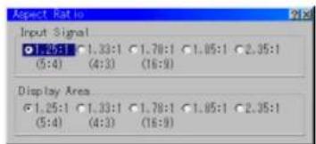
You can select the aspect ratio for input signal and display area respectively.
Select the appropriate aspect ratio using the SELECT ◀. ▶. ▲, or ▼ button.
NOTE: When 'Resolution' is set to 'Native', this feature is not available, and the stored settings and adjustments are invalid.
Resolution (when Auto Adjust is off):

This allows you to activate or deactivate the Advanced AccuBlend feature.
Auto .... Tums on the Advanced AccuBlend feature. The projector automatically reduces or enlarges the current image to fit the full screen.
Native.....Turns off the Advanced AccuBlend feature. The projector dis-
Video Filter

This feature reduces video noise. Select the appropriate filter for your signal.
Bar 0 .... Off
Bar 1/3 ...... High
Bar 2/3 ...... Medium
Bar full ..... Low
Blanking
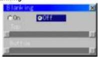
This feature allows you to mask any unwanted area of the screen image.
Blanking On/Off:
This setting enables or disables the blanking function.
On .... Blanking function is enabled.
Off...... Blanking function is disabled.
* Adjustment of vertical display range
Adjust the Top or Bottom blanking with the SELECT◀ or ▶ button.
Video Adj

Color Matrix
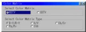
First, select an appropriate color matrix for your input signal, either HDTV or SDTV. Then select an appropriate matrix type from B-Y/R-Y, Cb/Cr, Pb/Pr or IVX.
NOTE: The Color Matrix feature is available for component video signal only.
Y/C Delay (not available for RGB)

Adjusts Y/C delay level.
Telecline

Use 3:2 pull down correction to eliminate jitter and artifacts in video.
Auto.... For film source such as a DVD player Off..... For signals other than film sources
Motion Select:
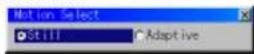
Sets the interpolation method. Selects Still or Adaptive. Still is used for non moving images such as a document camera. Select Adapter for all motion video.
Motion Level

Option Adj

Clamp Timing:

According to the signal, this function sets the detection position (i.e., clamp position) of the black level reproduction of the analog input signal. Normally this is not used. (1080P is set as the default)
Auto ...... This is the normal setting.
Tri-Sync ..... This is set when projecting HDTV video.
Front Porch .. This is set when the picture quality does not improve even though Auto or Tri-Sync has been set.
Adjust .... This permits the video clamp position for each signal to be set. Use "Adjust" when a clamp timing error occurs at the time of special analog signal reception such as 1080P. Note that "Adjust" is not valid for doubler signals such as NTSC and PAL.
To delete the "Clamp Timing" setting screen, select the SELECT button and press the ENTER button, or press the remote control CANCEL button.
Sync Protection

When a VCR, DVD, or some other equipment that supports Copyguard (a copy prevention system) is played back, the screen may be displayed in a curved manner. Adjustments are made in such circumstances. Use the SELECT ◀ or ▶ button to adjust the VD level.
Lens Memory

This function serves to store the adjusted value when using the Shift, Focus, and Zoom buttons of the main unit or the remote control.
Usage Example
When you wish to display on a screen having a 4:3 aspect ratio an NTSC or other 4:3 aspect ratio signal and an SXGA or other 5:4 aspect ratio signal:
Perform shift, focus, and zoom adjustments to set the vertical screen size of the vertically long 5:4 aspect ratio signal to standard.
Both 4:3 apsect ratio signals and 5:4 aspect ratio signals can now be displayed.
Note that with these shift, focus, and zoom adjustments, the 4:3 aspect ratio signal will become smaller on the screen.
To eliminate this size reduction, adjust the shift, focus and zoom to the optimum condition for each of the 4:3 aspect ratio signal and the 5:4 aspect ratio signal. Memory (storage) of each of these values will permit projection at an optimum condition upon signal switching.
1) Select "Projector Options" → "Setup" → "Page 4" → "Lens Memory" and then insert a check mark into the Lens Memory check box.
2) Set to no-signal condition or project a 5:4 aspect ratio signal and then adjust each of shift, focus, and zoom.
3) Select "Reference" under "Adjust(Source)" → "Lens Memory" → "Refer-
* For signals other than those having a 5:4 aspect ratio (or, 5:4 aspect ratio signals that you wish to adjust separately), adjust shift, focus, and zoom, select "Custom" under "Reference/Custom", then press, "Store".
The differences between 'Reference' and 'Custom' are described below.
"Reference": Valid adjustment value for a no-signal condition and a newly input signal "Custom": Custom adjustment value for a specific signal
Note that when "Reference" is stored, it will be overwritten since it is
Switcher (available only when used with ISS-6020)

Switcher Gain
This feature adjusts the input level of the signal. This must be done to each color: R, G, and B.
Volume

This feature adjusts the volume of the audio output. Adjust the sound corresponding to the slot.
Ref Adj

Keystone

This feature corrects the keystone (trapezoidal) distortion to make the top of the screen longer or shorter to be the same as the bottom. Use the ◀ or ▶ buttons on the slide bar to correct the keystone (trapezoidal) distortion.
Lamp

Lamp Mode
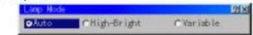
This feature allows the lamp power supply to operate under three settings.
Auto .... This setting keeps the projector's original light output level for a certain period of time.
High-Bright (SX6000 only)
...... This setting consumes maximum current from the AC input and results in the most light output.
NOTE: The High Bright mode shortens the lamp life. Be sure to use this mode at temperature of 95°F (35°C) or less.
Variable..... This setting allows the lamp power supply to draw a variable amount of current from the AC input source and allows for maximum power consumption and variable light output.
Lamp Output

When selecting "Variable", use the slidebar to adjust for desired projector light output.
Reference White Balance
This feature adjusts the white balance that is used as a reference. This adjustment affects all sources. The Ref. White Bal. is available for test pattern only.
Factory Default

Projector Options
Enables you to set preferences and other operating options.
Timer

Enables you to turn on or off your projector automatically at a specified time. Two timer functions are available: On/Off Timer and Sleep Timer.
[On/Off Timer]
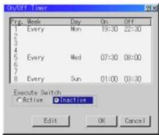
Up to eight settings can be programmed.
- Before setting On/Off Timer, make sure that Date, Time Preset feature is set
- To enable your setting, select Active on the Execute Switch.
- Select OK and press the ENTER button on the remote control to complete the setting.
NOTE: When On Timer is set and the projector is in the standby mode, the Status indicator flashes green to show that On Timer program is active. The projector must be in stand-by mode at the time of turning on. The preset power-on time will be void if the cooling fan is working or an error occurs. Unplugging the projector cancels your 1 Week programs regardless of whether the program was executed or not. However, your Every Week program will not be cancelled even if you unplug the projector.
Sleep Timer
![NEC MultiSync SX6000 - [On/Off Timer] - 2](/content/2026/06/1215723/images/916de27b6e5fce4f378502be57a5912675b8017de432a5ccca2c709a1ff012a2.jpg)
- Select your desired time between 30 minutes and 2 hours in 30 minute increments.
- Select Set and press the ENTER button on the remote control.
- The remaining time starts counting down.
- The projector will turn off after the countdown is complete.
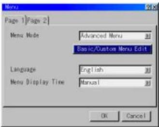
Menu
![Menu Page 1 [Page 2] Menu Mode Advanced Menu Basic/Custom Menu Edit](/content/2026/06/1215723/images/48274c4c0c778c67533ec6160e34a4110cfa2c3c5b94daa90ffdee50c8aa3257.jpg)
Menu Display Time :
This option allows you to select how long the projector waits after the last touch of a button to turn off the menu. The preset choices are "Manual", "Auto 5 sec", "Auto 10 sec", and "Auto 30 sec". The "Manual" is the factory preset.
Manual .... The menu can be turned off manually. Auto 5 sec .... The menu will automatically be turned off in 5 seconds if no buttons are pressed within 5 seconds. Auto 10 sec.. The menu will automatically be turned off in 10 seconds if no buttons are pressed within 10 seconds. Auto 30 sec.. The menu will automatically be turned off in 30 seconds if no buttons are pressed within 30 seconds.
[Page 2]

Display Select:
You can choose the desired status information to be displayed on the screen. The desired status information will be displayed each time you switch between sources.
Date Format:
Eight display formats can be selected. This date format sets the current date that appears on the upper left corner of the screen.
Date, Time Preset:
Setting the Current Date and Time
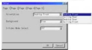
Setup
Enables you to set operating options.
Press "OK" to save your changes for all the features of Page1, Page2, Page3, Page 4 and Page5.
[Page 1]

Orientation
This reorients your image for your type of projection.
The options are: desktop front projection, ceiling rear projection, desktop rear projection, and ceiling front projection.
Background
Use this feature to display a blue/ black screen or logo when no signal is available. The default background is blue.
S-Video Mode Select
This feature is used to select the S-Video signal detection mode.
This allows identifying of the S-Video signals with different aspect ratio (Zoom signal 16:9, Wide Zoom signal 4:3).
S2....Identities Zoom or Wide Zoom signal.
OFF .... Does not identify any S-video signal.
[Page 3]

Signal Select (VIDEO 1/2, S-VIDEO1/2 and Switcher)
This feature enables you to select composite video standards manually. Normally select "Auto".
Select the video standard from the pull-down menu. This must be done for Video and S-Video separately.
"Switcher" is setting for Video and S-Video in SW 1 Level or 2 mode.
[Page 4]

Keystone Save
This option enables you to save your current keystone settings.
Saving your change once affects all sources. The changes are saved when you turn off the projector.
Doubler (Video / S-Video Only)
This sets double speed interpolation of the video signal.
On .... Non-interlaced display
Cif.... Interlaced display
NOTE: The setting will take effect from the next video signal display.
Lens Memory
This function applies the stored lens shift, focus, and zoom adjustment values to the selected signal.
The function performs a setting that enables or disables the "Adjust (Source)" - "Lens Memory" functions of the menu.
- On -- Enables the lens memory function and apply the stored shift, focus, and zoom setting values to the selected signal.
- Off -- Disables the lens memory function so that there will be no application of stored shift, focus, and zoom setting values.
NOTE: The shift, focus, and zoom adjustment values can be stored regardless of whether or not the lens memory function is enabled.
NOTE: In the Link mode the Lens Memory feature is not available.
User Name
Type in your desired name using the INPUT buttons on the remote control.
Select one character at a time with the INPUT buttons 1 through 10(0) and by moving the cursor with the SELECT button. The user name must be 18 characters or less.
Only after completely finishing the selection of the characters, press ENTER.
[Page 5]
![NEC MultiSync SX6000 - [Page 5] - 1](/content/2026/06/1215723/images/f00df4f9ca7449da1d1564d2327ff0e6fde8c11243bc99675c7b91068567b686.jpg)
Default Source Select
You can set the projector to default to any one of its inputs each time the projector is turned on.
Last..... Sets the projector to default to the previous or last active input each time the projector is turned on.
Select ...... Displays the selected source input every time the projector is started up. Select an input from the pull-down menu.
Link Mode

This feature is used for multiple projector connection using RGB Digital Input/Output connectors. The master projector is set to Master. The other slave projectors are set to Slave. When not using Link mode, set to Standalone. See page E-14 for setting up for double stacking in link mode.
Switcher Control

This feature sets the projector in communication with the NEC ISS 6020 Switchers.
Stand Alone.....Use the projector in stand alone operation. SW 1 Level.....Use the projector with one Switcher. (not available in Link mode) SW 2 Level.....Use the projector with two or more Switchers. (not available in Link mode)
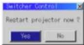
When changing this setting, the confirmation message will appear. If you want to restart your projector, select Yes; if not, select No. NOTE: This setting becomes effective only after the projector is restarted.
Source Information

Displays the status of the current signal. This dialog box has three pages.
Projector Information
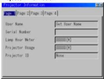
Displays the information for your projector such as lamp usage, serial number and version number etc..
Reconnect button .....Confirms connection of all linked projectors
Status items:
Running ....The projector is now working Cooling Lamp ....The fan is now cooling the lamp Standby ....The projector is in stand-by Communication Error .A communication error has occurred Connecting....The projector is now verifying for connection Error Standby ....An error caused the projector to enter the stand-by mode.
Test Pattern

Press to display the test pattern. Pressing this button sequentially selects five test patterns.
Selecting a new signal that is close to one of the listed signals in horizontal and vertical frequency
Selecting a new signal that is close to one of the listed signals in horizontal and vertical frequency may not display the image correctly because the new signal is considered as one of the registered signals listed in the Entry List. (In this case the Auto Adjust feature may not work correctly.)
To use both signals, use different input terminal (RGB 1, RGB 2 or RGB 3) respectively, or assign specific remote keys for signals.
- Cut an existing signal from the Entry List.
1) Select another signal other than the one currently projected because the currently projected signal cannot be cut.
2) Press the ENTRY LIST button on the supplied remote control.
3) After selecting the existing signal, press and hold down the CTL button
6. SPECIFICATIONS
Optical
Panel *1
DMD™ .9" × 3
1280 x 1024 native resolution up to 1600 x 1200 with advanced AccuBlend™ Technology
Lamp 1.0kW Bubble Type Short Arc Xenon
Built in: Overheat Protection
Lamp Over-Usage Protection
Light Output SX6000 : 5000 ANSI Lumens (High Bright mode)
4300 ANSI Lumens (Normal mode)
SX4000 : 3500 ANSI Lumens (Variable mode at max)
Full Light Output at 200-240V
Brightness Uniformity >80% edge to center
Contrast Ratio 400 : 1 Full On/Off
250:1 ANSI
Lens Movement Motorized Horizontal and Vertical Lens Shift
Built in Lens Shutter
Lens Options ^2
TL-08SF 0.84 (Short local lens)
Scan Rate Horizontal: 15 - 107 kHz
Vertical
Pixel Clock
24 - 105 Hz
200MHz (MAX)
Inputs
RGB / YCr/Pr,Cb/Pb
(2) BNC
RGB H (HV) V (1) D-dub 15 pin
YPbPr / YCrCb (1) RCA
Video (1) BNC (1) RCA
S-Video (1) S-Video Terminal
External Control RS232C(1) D-sub 9 pin
Contact Closure
Switcher (2) D-sub 15 pin In/Out
Addressable Remote Control (wired / wireless)
Power Requirement 100-120 / 200-240 VAC, 50/60Hz
Input Current 11 / 7.5 A
Power Consumption 1.1 / 1.5 kW
Mechanical
Installation Orientation: Floor/Front, Floor/Rear, Ceiling/Front, Ceiling/Rear
Stacking: Up to 3 projectors can be gravity stacked
Dimensions 22.0" (W) x 26.9" (D) x 11.8" (H) / 560 mm (W) x 682 mm (D) x 300 mm (H)
with lens hood and foot
(not including handle, stacking pad and protrusions)
Net Weight 94.8 lbs (43Kg) (not including lens)
Environment
Operational Temperature 40° to 95°F / 5° to 35°C,
Humidity: 20-80% non-condensing
Storage: 14° to 122°F / -10° to 50°C
Regulations
USA UL 1950 FCC Class A
Canada CSA950 (C-UL)
Europe EN60950 EN55022 Class A
Japan J60950 VCCI
Oceania EN60950 AS/NZS3548
Asia EN60950 CISPR22
EN55024 EN61000-3-2 EN61000-3-3
Class A
Class A
*1: SX6000: Permissible deviation for RGB convergence (Pixel deviation) is 3/4 pixel or less at center: 1 pixel or less around the perimeter (when projection upward angle is 0°).
SX4000: Permissible deviation for RGB convergence (Pixel deviation) is 1 pixel or less at center; no space between two color pixels around the perimeter (when projection upward angle is 0^ ).
*2: When using the zoom lens, it is recommended that the projector is positioned at an angle of from -15 to +15 degrees from the horizontal.
Classifications are subject to changes without notice
7. Optional Accessories
| Lens TL-08SF (Short Focal Lens 0.84) : 10kgTL-12/12H (Zoom Lens 1.5 - 2.5:1) : 5.5kgTL-22 (Zoom Lens 2.5 - 4.0:1) : 4.5kgTL-42 (Zoom Lens 4.0 - 7.0:1) : 4.5kg |
| Interface Board XT SDI BOARDSX HDSDIX DIGITAL RGB BOARD |
| Ceiling Mount Kit XT CMKIT |
| Switcher ISS-6020 Video/RGB Switcher |
Three Interface boards are optionally available.
XT SDI BOARD
This board accepts the input of non-compressed signal sources such as commercial type digital VTR (e.g., D1/D5-VCR) compatible with digital serial component signals (of the SMPTE 259M-C standard) and provides a high quality image without quantization noise. Note that the BNC cable used with the SDI connector should be Belden 8281 cable, or 3C-2V equivalent cable or better. Packaged items: SDI board (1), shield case (1), connector cable (1), and installation manual (1)
SX HDSDI Board
This board accepts the input of non-compressed signal sources such as commercial type digital VCR (DS-VCR) compatible with digital serial component signals (of the SMPTE 292M standard) and provides a high quality image without quantization noise. This board accepts the following image formats.
| System | Number of samples of active I line | Number of active lines in 1 frame | Frame rate (Hz) | Scanning format | Sampling frequency (MHz) | Total number of samples in 1 line (bit) | Total number of lines in 1 frame |
| 1920x1035/80/2:1 | 1920 | 1035 | 30 | 2:1 Interface | 74.25 | 2200 | 1125 |
| 1920x1080/80/2:1 | 1920 | 1080 | 30 | 2:1 Interface | 74.25 | 2200 | 1125 |
| 1280x720/60/1:1 | 1280 | 720 | 60 | Progressive | 74.25 | 1650 | 750 |
| 1920x1080/24(μF) | 1920 | 1080 | 24 | Progressive | 74.25 | 2750 | 1125 |
Note that the BNC cable used with the HDSDI connector should be 5C-FB equivalent cable or better.
Packaged items: HDSDI board (1), shield case (1), connector cable (2), flat cable (1), set screw for shield case (2) and installation manual (1)
X DIGITAL RGB BOARD
Consult your dealer for the optional X DIGITAL RGB BOARD.
8. Compatible Input Signal List
Compatible Input Signal List
| Signal Name Resolution (H×V) | Horizontal Frequency Vertical Frequency | ||
| Video (NTSC) | 640 × 480 | 15.734 | 60.0 |
| Video (PAL/SECAM) | 768 × 576 | 15.625 | 50.0 |
| Video (HDTV) | 640 × 480p | 31.5 | 60.0 |
| 1280 × 720p | 45.0 | 60.0 | |
| 1920 × 1035 | 33.75 | 60.0 | |
| 1920 × 1080p | 28.13 | 25.0 | |
| 1920 × 1080p | 33.72 | 30.0 | |
| 1920 × 1080i | 28.13 | 50.0 | |
| 1920 × 1080i | 33.75 | 60.0 | |
| 1920 × 1080i | 26.97 | 47.95 | |
| 1920 × 1080p | 26.97 | 23.98 | |
| IBM PC or Compatibles | 640 × 350 | 31.5 | 70.0 |
| 640 × 400 | 37.9 | 85.0 | |
| 720 × 400 | 37.0 | 85.0 | |
| 640 × 480 | 31.5 | 60.0 | |
| 640 × 480 | 37.9 | 72.8 | |
| 640 × 480 | 37.5 | 75.0 | |
| 640 × 480 | 43.3 | 85.0 | |
| 800 × 600 | 35.2 | 56.3 | |
| 800 × 600 | 37.9 | 60.3 | |
| 800 × 600 | 48.1 | 72.0 | |
| 800 × 600 | 46.9 | 75.0 | |
| 800 × 600 | 53.7 | 85.0 | |
| 1024 × 768 | 48.4 | 60.0 | |
| 1024 × 768 | 56.5 | 70.1 | |
| 1024 × 768 | 60.0 | 75.0 | |
| 1024 × 768 | 68.7 | 85.0 | |
| 1152 × 864 | 67.5 | 75.0 | |
| 1280 × 960 | 60.0 | 60.0 | |
| 1280 × 1024 | 64.3 | 60.0 | |
| 1280 × 1024 | 80.0 | 75.0 | |
9. List of Menu Items Available on Link Mode
See the table below for available functions in the digital link mode and the analog link mode.
See the table below for available functions in the digital link mode (SX6000 only) and the analog link mode
* The digital signals available in the Link mode are the VESA compatible-signals except interlaced signals of VGA@60Hz to SXGA@75Hz.
* The VESA compatible signals that can connect to the master projector as analog input and connect to the slave projector as digital output are
interlaced signals of SVGA@85Hz, XGA@60Hz, XGA@70Hz, XGA@75Hz, XGA@85Hz, SXGA@60Hz and SXGA@75Hz.
* Video (NTSC, PAL, SECAM), YCbCr(50Hz/60Hz), 480p, 720p, SDI (525/625) signals can be supported.
Use a commercially available distribution amplifier to connect each projector when connecting the other signals.
| Function Link mode | ||||
| Menu Source Select L | ||||
| Adjust(Source) Picture | L | |||
| White Balance L | ||||
| Image Pixel Adjust L | ||||
| Position N | ||||
| Aspect Ratio L | ||||
| Resolution L | ||||
| Overscan L | ||||
| Video Filter L | ||||
| Blanking N | ||||
| Video Adj N | ||||
| Option Adj | N | |||
| Lens Memory | N | |||
| Signal Type | N | |||
| Switchor | N | |||
| Ref Adj | Keystone | N | ||
| Lamp | N | |||
| Ref. White Bal. | N | |||
| Factory Default | N | |||
| Projector Options | Timer | L | ||
| Menu | M | |||
| Setup | N | |||
| Link Mode | M | |||
| Switcher Control | N | |||
| Help | M | |||
| Test Pattern | N | |||
| Direct Button | LENS SHIFT | Projector | I | |
| Remote Control | N | |||
Appendix
Dimensions
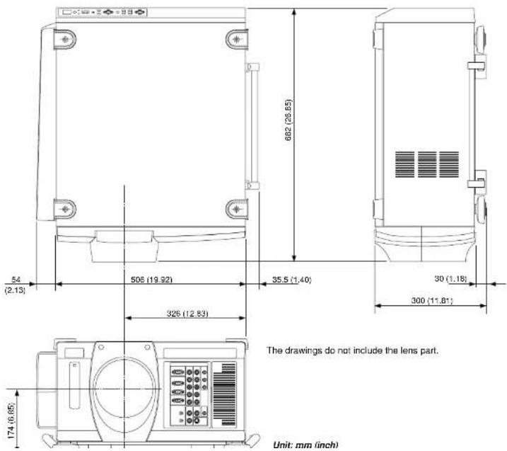
NEC
- NEC
- WARNING
- AVERTISSEMENT
- CAUTION
- ATTENTION
- Important Safeguards
- Installation
- To Dealer or Installer:
- Power Supply
- Fire and Shock Precautions
- Lamp Caution: Please read before operation
- Recommendations importantes
- LIMITED WARRANTY (USA and Canada only)
- HOW LONG IS THE WARRANTY
- WHO IS PROTECTED
- WHAT IS COVERED AND WHAT IS NOT COVERED
- WHAT NEC WILL COVER
- LIMITATION OF IMPLIED WARRANTIES
- EXCLUSION OF DAMAGES
- HOW STATE LAW RELATES TO THE WARRANTY
- TABLE OF CONTENTS
- INTRODUCTION
- PART NAMES AND FUNCTIONS
- INSTALLATION
- BASIC OPERATION
- CONNECTIONS
- OPERATION
- Introduction to the MultiSync SX6000/SX4000 Projector
- Features you'll enjoy :
- Getting Started
- What's In The Box?
- Controls
- Power Button
- Power Indicator
- Status Indicator
- Cancel Button
- Select (Up/Down/Left/Right) Button
- Menu Button
- Zoom Button
- ENTER
- SELECT (Up/Down/Left/Right)
- ADJUST WHITE BAL
- ADJUST PICTURE
- IMAGE/PROJECTOR
- INPUT
- POSITION
- MUTE SOUND
- MUTE OSD
- MUTE PICTURE
- KEYSTONE (R)
- AMPLITUDE (G)
- ENTRY LIST (B)
- FOCUS (+/-)
- MAGNIFY/ZOOM (+/-)
- Remote Control Precautions
- Remote Control Battery Installation
- Setting Up Your Projector
- Screen Size and Projection Distance
- Lens Shift Adjustable Range
- Maximum Possible Range for TL-1Z/1ZH, TL-2Z and TL-4Z
- Moving The Projector
- Pulling Out the Handles
- Selecting A Location
- Connecting the Power Cable and Turn on the Projector
- About Startup Screen
- Set up the projector
- Keystone
- Setting up for Double or Triple Stacking in Link Mode
- 2) Hookup
- Projector Orientation
- Ceiling Front Projection
- Ceiling Rear Projection
- When used in standalone operation
- Connecting Your PC Or Macintosh Computer
- Connecting Your Document Camera
- Connecting Your VCR Or Laser Disc Player
- When Used with One Switcher (ISS-6020/ISS-6020G)
- When Used with Two or More Switchers (100 Inputs)
- How to make connections:
- NOTE:
- REMOTE 1 Connector
- Operating Multiple Projectors with Remote Control
- Using the RGB DIGITAL connectors (SX6000 only)
- Link Mode
- General Controls
- Turn On The Projector
- Select The Computer Or Video Source
- Adjust The Image
- Turn Off The Projector
- IMPORTANT:
- Shutter mechanism
- Customizing Basic/Custom Menu
- Menu Tree
- Menu Elements
- Menu Descriptions & Functions Source Select
- Swicher
- Entry List
- Entry Edit Command
- Adjust (Source)
- Picture
- Brightness
- Contrast
- Saturation
- White Balance
- Color Temperature
- Signal Level
- Image
- Horizontal/Vertical Position (when Auto Adjust is off):
- Aspect Ratio (not available for RGB):
- Resolution (when Auto Adjust is off):
- Video Filter
- Blanking
- Video Adj
- Color Matrix
- Y/C Delay (not available for RGB)
- Telecline
- Motion Select:
- Motion Level
- Option Adj
- Clamp Timing:
- Sync Protection
- Lens Memory
- Usage Example
- Switcher (available only when used with ISS-6020)
- Switcher Gain
- Volume
- Ref Adj
- Lamp
- Lamp Output
- Reference White Balance
- Factory Default
- Projector Options
- Timer
- [On/Off Timer]
- Menu Display Time :
- Display Select:
- Date Format:
- Date, Time Preset:
- Setup
- Orientation
- Background
- S-Video Mode Select
- Keystone Save
- Doubler (Video / S-Video Only)
- User Name
- [Page 5]
- Default Source Select
- Switcher Control
- Source Information
- Projector Information
- Status items:
- Test Pattern
- Selecting a new signal that is close to one of the listed signals in horizontal and vertical frequency
- SPECIFICATIONS
- Optical
- Mechanical
- Optional Accessories
- XT SDI BOARD
- SX HDSDI Board
- X DIGITAL RGB BOARD
- Compatible Input Signal List
- List of Menu Items Available on Link Mode
- Appendix
Brand : NEC
Model : MultiSync SX6000
Category : Video projector