
A5232FMO - Smart Home JUNG - Free user manual and instructions
Find the device manual for free A5232FMO JUNG in PDF.


| Product Type | Centre plate with radio receiver (Art. No. ..5232F..) and with sensor connection (Art. No. ..5232FS..) |
| Model Number | A5232FMO |
| Brand | JUNG |
| Category | Smart Home / Blind Control |
| Application | Manual and radio-controlled operation of electrically-driven venetian blinds, shutters, awnings |
| Radio Frequency | 433.05 – 434.79 MHz |
| Receiver Category | 2 |
| Maximum Teachable Transmitters | 30 |
| Brightness Threshold (FS model) | Approx. 5,000 – 80,000 lx (adjustable; factory preset approx. 10,000 lx) |
| Operating Temperature | 0 ... +55 °C |
| Switch-on Time | approx. 2 minutes |
| Switch-over Time | approx. 1 second |
| Power Supply | Mains voltage via venetian blind control insert (230 V AC typical) |
| Installation | By qualified electrician; mount on venetian blind control |
| Safety Precautions | Disconnect mains before installation; not for safety-critical applications (e.g., emergency stop) |
| Sensor Connection (FS model) | Available for sun sensor (Art. No. 32SD) via terminal block or plug |
| Sun Protection Function (FS model) | Automatic shading when brightness exceeds threshold; deactivates after manual or radio operation |
| Light Scene Integration | End positions can be saved to light scene buttons of a radio transmitter |
| End Position Setting | Upper and lower end positions configurable |
| Warranty | Legal warranty via specialty store according to national law |
| Accessories | Sun/dawn sensor Art. No. 32SD; extension flex Art. No. 32K |
| Conformity | EU Directive 2014/53/EU (Declaration of Conformity at www.jung.de/ce) |
| Manufacturer | Albrecht Jung GmbH & Co. KG, Vollmestraße 1, 58579 Schalksmühle, Germany |
Frequently Asked Questions - A5232FMO JUNG
User questions about A5232FMO JUNG
0 question about this device. Answer the ones you know or ask your own.
Ask a new question about this device
Download the instructions for your Smart Home in PDF format for free! Find your manual A5232FMO - JUNG and take your electronic device back in hand. On this page are published all the documents necessary for the use of your device. A5232FMO by JUNG.
USER MANUAL A5232FMO JUNG
Centre plate with radio receiver
Art. No.: ..5232F..
Centre plate with radio receiver and sensor connection
Art. No.: ..5232FS..
Operating instructions
1 Safety instructions
Electrical equipment may only be installed and fitted by electrically skilled persons.
Serious injuries, fire or property damage possible. Please read and follow manual fully.
Danger of electric shock. Always disconnect before carrying out work on the devise or load. In so doing, take all the circuit breakers into account, which support dangerous voltages to the device and or load.
Danger of electric shock. Device is not suitable for disconnection from supply voltage.
The radio communication takes place via a non-exclusively available transmission path, and is therefore not suitable for safety-related applications, such as emergency stop and emergency call.
These instructions are an integral part of the product, and must remain with the end customer.
2 Device components
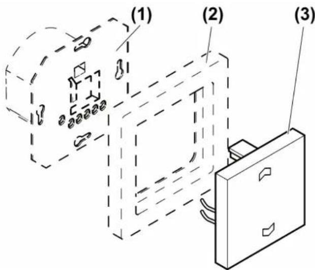
Figure 1: Device components
(1) Venetian blind control
(2) Frame
(3) Radio cover
3 Function
System information
By statute, the transmitting power, the reception characteristics and the antenna cannot be changed.
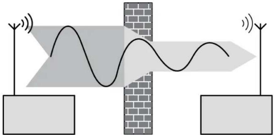
The range of a radio system from the transmitter to the receiver depends on various circumstances.
The range of the system can be optimised by selecting the optimal installation location, taking into account the structural circumstances.
natural_image
Diagram showing signal wave propagation through a brick wall with two antennas and a wavy line, no text or symbols present.Figure 2: Reduced range due to structural obstacles
Example of penetration of various materials:
| Material Penetration | |
| Wood, Plaster, Plasterboard approx. 90% | |
| Brick, Chipboard approx. 70% | |
| Reinforced concrete approx. 30% | |
| Metal, Metal grid approx. 10% | |
| Rain, Snow approx. 1-40% |
Intended use
- Manual and radio-controlled operation of electrically-driven Venetian blinds, shutters and awnings
- Operation with suitable radio transmitters
- Operation on insert of the Venetian blind management system
Product characteristics
- End positions of the Venetian blind can be called up via light scenes
Additional functions for the cover with sensor connection
- Connection of a sun sensor (Accessories)
- Brightness threshold settable
Sun protection function for cover with sensor connection
The connection of a sun sensor (accessory) enables automatic shading when it is very bright outside. The brightness threshold that controls the sun protection can be adjusted on the cover. If the measured brightness exceeds the predefined brightness threshold for more than 2 minutes, the Venetian blind moves to the position defined by the sun sensor.
The sun protection can first be activated if the Venetian blind has been moved to the upper end position and deactivated automatically after 2 minutes. Each manual or radio operation deactivates the sun protection.
If the brightness threshold is fallen short of for more than 15 minutes, the Venetian blind moves back to the upper end position.
4 Operation
Moving the Venetian blind
■ Press top or bottom of cover for longer than one second. The Venetian blind moves in the desired direction to the end position or stops when the button is pressed again.
Adjusting the slats
■ Press top or bottom of cover for shorter than one second.
The slat position changes in the desired direction for as long as the button is pressed.
Operation with radio transmitter
A radio transmitter has to be taught in order to be able to operate the venetian blind via radio.
i Observe the instructions for the radio transmitter.
The slats are adjusted or the Venetian blind is moved depending on how long a radio transmitter is actuated.
5 Information for electrically skilled persons
5.1 Fitting and electrical connection

DANGER!
Electrical shock when live parts are touched.
Electrical shocks can be fatal.
Before carrying out work on the device or load, disengage all the corresponding circuit breakers. Cover up live parts in the working environment.
Fitting the device
The Venetian blind control is mounted and connected properly (see instructions for the relevant Venetian blind control).
In the case of covers with sensor connections, install the sensor cable, adjust the brightness threshold and fasten the sun sensor to a window (see following chapter):
■ Mount the radio cover with the frame onto the Venetian blind control (figure 1).
■ Switch on mains voltage.
Installing the sensor cable
for covers with sensor connections
The sensor cable carries safety extra-low voltage (SELV). Observe fitting instructions according to VDE 0100.
The sensor cable can be installed in three different ways. In-wall routing (figure 3), surface-mounted routing (figure 4), and with appropriate covers plugging the sensor cable into the cover.
The sensor cable must not be too long, because otherwise interference from other loads and cables may occur. This may result in malfunctions. Therefore use only shielded cables, and connect the shielding to earth. The total length must not exceed 20 m; avoid proximity to other electrical facilities.
Routing the sensor cable in-wall
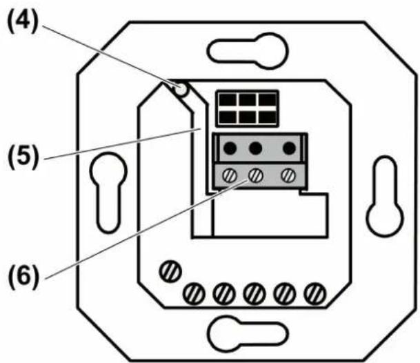
Figure 3: In-wall routing of the sensor cable
For in-wall routing of the sensor cable, use only shielded cables. Recommendation: J-Y(ST)Y 2x2x0.6 mm.
- Insert the cable through the hole (4) in the insert and route it through the cable duct (5) to the terminal block (6) (figure 3).
i The terminal block is included with the covers with sensor connection.
■ Connect the cable (see "Connecting sensors to terminal block")
Routing the sensor cable with surface-mounting

Figure 4: Surface-mounted routing of the sensor cable
■ For surface-mounted routing of the sun sensor (8), cut off the plug.
- Route the sensor cable behind the supporting plate (7) and through the cable duct to the connecting terminal (6) (figure 4).
■ Connect the cable (see "Connecting sensors to terminal block")
Connecting sensors to terminal block
natural_image
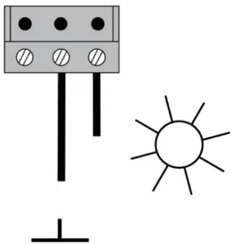
Simple diagram showing a battery with three terminals and a sun symbol (no text or labels)Figure 5: Connection to the terminal block
■ Connect the sun sensor with the correct polarity (figure 5) according to the connection diagram. The "earth" is identified for the sensor cable and the "sun" is identified for the extension cable (accessory).
i Interchanging the connections will result in malfunctions.
Plugging the sensor cable into the cover
It is only possible to connect the sun sensor to the cover if a corresponding socket is present. This is not the case for all covers with sensor evaluation.
■ Insert plug of sun sensor into the socket of the cover.
Fasten sun sensor to the window
The positioning of the sun sensor on the window determines the stop position of the Venetian blind when the sun protection is active. The Venetian blind comes to a stop slightly above the sun sensor.
■ Fasten sun sensor to the window (observe the instructions for the sun sensor).
Adjusting brightness threshold

Figure 6: Back of cover: Adjuster for brightness threshold
The brightness threshold can be adjusted within a range of approx. 5,000 Lux "small sun" to approx 80,000 Lux "large sun" using the adjuster (9) on the back of the cover (figure 6). The adjuster is preset to approx. 10,000 Lux at the factory.
- Adjust the brightness threshold to the required value. Adjust the brightness threshold value after commissioning if necessary.
5.2 Commissioning

DANGER!
Electrical shock when live parts are touched.
Electrical shocks can be fatal.
Before working on the device, cover up live parts in the working environment.
Teaching a radio transmitter
If all memory slots are occupied, a radio transmitter which has already been taught must first be deleted. To do this, delete all taught channels and light scenes of the radio transmitter individually.
The distance between the receiver and the radio transmitter is from 0.5 m to 5 m.
The load is switched off.
■ Press cover over entire surface for approx. 4 seconds.
The device is in programming mode for approx. 1 minute and indicates this with a pulsating tone.
- Trigger teach telegram on radio transmitter (see instructions for radio transmitter).
The cover confirms that the learning process was successful with a continuous acoustic tone.
■ Press cover briefly.
The device is in operating mode.
i The programming mode is exited automatically after about 1 minute.
i Teach light scene buttons separately.
Deleting radio transmitters individually
■ Teach the radio transmitter to be deleted again (see Teaching a radio transmitter).
Cover confirms this with a fast pulsating tone. The radio transmitter has been deleted.
If several channels or light scenes of a radio transmitter have been taught, they all must be deleted individually.
Integrating the end position of the Venetian blind into a light scene
The upper or lower end position of a Venetian blind can be called up via light scene buttons of a radio transmitter.
Light scene button of the radio transmitter has been taught in the actuator.
■ Move Venetian blind to the desired end position. The relay of the Venetian blind control must switch off automatically after two minutes.
■ Press desired light scene button of the radio transmitter for at least 3 seconds.
The end position of the Venetian blind has been saved as a light scene.
6 Appendix
6.1 Technical data
Ambient temperature 0 ... +55 °C
Switch-over time for direction change approx. 1 s
Switch-on time approx. 2 min
Brightness setting
Art. No. ..5232F.. —
Art. No. ..5232FS.. approx. 5000 ... 80000 lx
Radio frequency 433.05 MHz ... 434.79 MHz
Receiver category 2
Teachable radio transmitter max. 30
6.2 Troubleshooting
The sun protection is not performed properly, instead the Venetian blind moves into the direction of the lower end position.
Cause: Sun sensor is connected in reverse polarity.
Connect the sun sensor with the correct polarity.
6.3 Accessories
Sunlight / dawn sensor Art. No. 32SD
Extension flex Art. No. 32K
6.4 Conformity
Albrecht Jung GmbH & Co. KG hereby declares that the radio system type
Art. No. ..5232F.. / ..5232FS..
corresponds to the directive 2014/53/EU. You can find the full article number on the device. The complete text of the EU Declaration of Conformity is available under the Internet address:
www.jung.de/ce
6.5 Warranty
The warranty follows about the specialty store in between the legal framework as provided for by law.
ALBRECHT JUNG GMBH & CO. KG
Vollmestraße 1
58579 Schalksmühle
GERMANY
Telefon: +49 2355 806-0
Telefax: +49 2355 806-204
kundencenter@jung.de
www.jung.de


- Operating instructions
- Safety instructions
- Device components
- Function
- System information
- Intended use
- Product characteristics
- Sun protection function for cover with sensor connection
- Operation
- Moving the Venetian blind
- Adjusting the slats
- Operation with radio transmitter
- Information for electrically skilled persons
- Fitting and electrical connection
- DANGER!
- Fitting the device
- Installing the sensor cable
- for covers with sensor connections
- Routing the sensor cable in-wall
- Routing the sensor cable with surface-mounting
- Connecting sensors to terminal block
- Plugging the sensor cable into the cover
- Fasten sun sensor to the window
- Adjusting brightness threshold
- Commissioning
- Teaching a radio transmitter
- Deleting radio transmitters individually
- Integrating the end position of the Venetian blind into a light scene
- Appendix
- Technical data
- Troubleshooting
- Accessories
- Conformity
- Warranty
- ALBRECHT JUNG GMBH & CO. KG
Brand : JUNG
Model : A5232FMO
Category : Smart Home