
U-01S - Audio Modules TOA - Free user manual and instructions
Find the device manual for free U-01S TOA in PDF.

| Product Type | Audio Module - Unbalanced Line Input |
| Model Number | U-01S |
| Series | TOA 900 Series |
| Input Type | Unbalanced line level |
| Input Impedance | 220 kΩ |
| Sensitivity | -18 to +12 dBu |
| Gain Range | -30 to 0 dB |
| Signal-to-Noise Ratio | 90 dB |
| Connector Type | Removable terminal block (3-pin) |
| Power Supply | +24 VDC (from host unit via edge connector) |
| Current Consumption | Approximately 25 mA (typical) |
| Frequency Response | 20 - 20,000 Hz (±1 dB) |
| Distortion | Less than 0.05% |
| Controls | Gain control on faceplate |
| Compatible Host Units | A-900MK2, M-900MK2, P-900MK2 series and others (see manual compatibility chart) |
| Maximum Cable Length | 15 feet (unbalanced source should be adjacent) |
| Operating Temperature | 0°C to 40°C (estimated standard) |
| Dimensions (WxHxD) | Approximately 1.6" x 5.25" x 6.0" (standard TOA module, estimated) |
| Weight | Approximately 0.5 lbs (estimated) |
| Installation | Insert into empty module slot, secure with supplied screws |
| Maintenance | None required; keep dry and dust-free |
Frequently Asked Questions - U-01S TOA
User questions about U-01S TOA
0 question about this device. Answer the ones you know or ask your own.
Ask a new question about this device
Download the instructions for your Audio Modules in PDF format for free! Find your manual U-01S - TOA and take your electronic device back in hand. On this page are published all the documents necessary for the use of your device. U-01S by TOA.
USER MANUAL U-01S TOA
900 Series Module Guide


2007
TABLE OF CONTENTS
INTRODUCTION....1
MODULE SELECTION ....3
MODULE CATEGORIES
MODEL NUMBERS
SIGNAL LEVELS
INSTALLATION NOTES
MODULE SELECTION CHART 5
MUTING 7
MICROPHONE INPUT MODULES 9
ML-11T Microphone/Line Input with Mute Send/Receive 9
M-01 Series Microphone Input 9
M-11S Microphone Input with Mute-Receive 10
M-21S Microphone Input with Remote Volume Control 10
M-41S Microphone Input with Mute-Send 11
M-51 Series Microphone Input with Voice Gate 11
M-61 Series Microphone Input with Compressor 12
M-03P High Impedance Microphone Input 12
LINE INPUT MODULES 13
ML-11T Microphone/Line Input with Mute Send/Receive....13
B-01 Series Balanced Line Input 13
B-11S Balanced Line Input with Mute-Receive....14
B-21S Balanced Line Input with Remote Volume Control 14
B-41S Balanced Line Input with Mute-Send 15
L-01 Series Line Matching Input 16
L-11S Line Matching Input with Mute-Receive 17
L-41S Line Matching Input with Mute-Send 17
U-01 Series Unbalanced Line Input 18
U-03 Series Unbalanced Line Input with High/Low Cut Filters 19
U-11 Series Unbalanced Line Input with Mute-Receive 19
U-12S Unbalanced Line Input with Variable Mute-Receive Depth 20
U-13 Series Unbalanced Line Input with High/Low Cut Filters and Mute-Receive 20
U-14R Dual Input Priority with AGC....21
U-21S Unbalanced Line Input with Remote Volume Control....21
U-43 Series Unbalanced Line Input with High/Low Cut Filters and Mute-Send 22
U-61S Unbalanced Line Input with Compressor 23
SPECIAL FUNCTION MODULES 24
LINE OUTPUT
T-01S Balanced Line Output....24
T-02S Unbalanced Line Input with Music-On-Hold Output 24
T-12S Unbalanced Line Input with Music-On-Hold Output and Input Mute-Receive....25
TONE GENERATOR
S-20S Digital Message/Tone with USB....25
S-01S 1 kHz Sine Wave Test Tone 26
S-02S Buzzer/Yelp Tone 26
S-04S Switch-Selectable Tone 27
REMOTE VOLUME CONTROL
V-01S Remote Master Volume Control (VCA)....27
SPEAKER PROCESSOR
E-03 Equalizer For F-121 28
E-04 Equalizer For H-1 28
E-05 Equalizer For H-2 28
E-06 Equalizer For H-3 28
E-07 Low Pass Filter For FB-100/HB-1 28
APPLICATIONS....30
- Paging Over Background Music ....30
- Telephone Paging and Music-On-Hold 30
- Banquet Room Sound System 30
- School Gymnasium Sound System ....31
- Mute Send and Receive Combination Using Two Modules....31
FREQUENTLY ASKED QUESTIONS ....31
General
- Which module should I use for a microphone?
- Which module should I use for a wireless microphone receiver?
- Which module should I use for an AM/FM tuner, cassette deck, CD player, computer sound card, juke box, mixer or satellite receiver?
- Which modules should I use for telephone or microphone paging with priority over a music source?
5.Which module should I use for Music-On-Hold (MOH)?
6.What type of potentiometer do I need for a Remote Volume Control module? - How do I use one of the 900 Series processor modules?
8.What is the proper wiring for the screw terminal type input modules?
9.What's the difference between the "L" Series and "B" Series modules? - Which modules are for "mute send"?
- Which modules are for "mute receive"?
Troubleshooting
- Why won't the M-11 (Microphone Input with Mute-Receive) pass signal?
- Why won't my paging source override my music source?
- Why isn't my condenser microphone working with an M Series module?
- Why is my signal level low with an L Series module?
MODULAR PRODUCTS REFERENCE CHART....33
MODULE CROSS-REFERENCE CHART 34
JUMPER SETTINGS CHART 35
CONNECTOR WIRING CHART....36
Welcome to the TOA 900 Series Module Guide!
In this guide, you'll find everything you need to take advantage of the powerful flexibility of 900 Series modular products — function descriptions; signal flow and wiring diagrams; specifications; jumper settings; application examples; and other useful information.
Understanding the modules will give you the freedom to configure custom systems FAST without complicated modifications. And as your customers' needs change, you can easily add more inputs or new functions by simply changing or adding modules.
An electronic version of the guide is also available for download at http://www.toaelectronics.com. If you have any questions, please contact TOA Product Support at 1-800-733-4748 — we're here to help!
TOA Electronics, Inc.
Dedicated to Bob Sweet, author of the original 900 Series Module Guide, 1990.
Module Categories
There are three main module categories -
- Mic
- Line
- Special Function
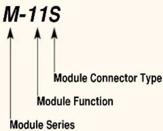
Model Numbers
TOA assigns module model numbers using the following convention: a-bbc, where "a" indicates the module "Series", "bb" indicates the module "Function", "c" indicates the module "Connector Type".
For example, with the M-11S module,
"M" indicates "Microphone" Series
"11" indicates "Mute Receive" Function
"S" indicates "Screw Terminal" Connector.
See the "Module Selection Chart" on page 5 for further details.
Signal Levels
There are three general categories of signal levels in audio.
1. Microphone (Mic) Level
• Typically 0.25 mV (-70 dBu) to 2.5 mV (-50 dBu)
• Examples include: microphones, wireless microphone receivers
2.Line Level
• Typically from 100 mV (-18 dBu) to 7.75 V (+20 dBu)
- Examples include: AM/FM tuners, CD players, cassette decks, computer sound cards, jukeboxes, satellite receivers, signal processors, telephone page outputs, wireless microphone receivers
3.Speaker Level
• Typically higher than 7.75 V (+20 dBu)
- Amplifier output for driving speakers
- TOA does not currently offer modules to accept Speaker Level signals (external pad required).
flowchart
graph TD
    A["Module Series"] --> B["Module Function"]
    B --> C["Module Connector Type"]
Notes:
- Connecting a Mic Level signal to a Line Input module usually results in very low, barely audible, output.
- Connecting a Line Level signal to a Mic Input module usually results in distorted output.
- NEVER connect a Speaker Level signal to a Mic or Line Input module - this will damage the module.
- The type of module connector does not necessarily indicate the input sensitivity. For example, there are both Mic and Line Input modules available with female XLR jacks.
Installation Notes
• Always turn the power OFF on the host unit before installing or removing modules.
- Before installing each module, check the supplied module installation sheet to determine if any configuration is required. See Jumper Settings on page 35 for a list of possible configurations.
- Always secure each module to the host unit's chassis with the supplied screws.
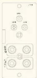
MODULE SELECTION CHART

Removable Terminal Block

Female XLR

Male
XLR
1/4"
Phone
Jack

1/4" Phone Jack

RCA Jack

Dual RCA
Jacks

5 Screw Terminals
| Microphone Input Modules | Mic/Line Input w/ Mute Send/Receive | ML-11T | ||||||
| Standard with high/low cut filters | M-01S | M-01F | M-01M | M-01P | ||||
| Mute-Receive with high/low cut filters | M-11S | |||||||
| Mute-Send with high/low cut filters | M-41S | |||||||
| Voice Gate with low cut filters | M-51S | M-51F | ||||||
| Compressor with high/low cut filters | M-61S | M-61F | ||||||
| Remote Volume Control with high/low filters | M-21S | |||||||
| For high-Z mic. only w/ high/low cut filters | M-03P | |||||||
| Line Input Modules* | Mic/Line Input w/ Mute Send/Receive | ML-11T | ||||||
| Standard, no special features | B-01S | L-01F | ||||||
| L-01S | B-01F | U-01P | U-01R | |||||
| U-01S | U-01F | |||||||
| Standard with high/low cut filters | U-03S | U-03R | ||||||
| Mute-Receive | B-11S | |||||||
| L-11S | U-11R | |||||||
| U-11S | ||||||||
| Mute-Receive with high/low cut filters | U-13S | U-13R | ||||||
| Mute-Receive with variable mute depth | U-12S | |||||||
| Mute-Send | B-41S | |||||||
| L-41S | ||||||||
| Mute-Send with high/low cut filters | U-43S | U-43R | ||||||
| Remote Volume Control | B-21S | |||||||
| U-21S | ||||||||
| Compressor | U-61S | |||||||
| Dual input priority w/AGC | U-14R | |||||||
| Special Function Modules | Line output | T-01S | ||||||
| Line input with Music-On-Hold (MOH) output | T-02S | |||||||
| Line input w/ MOH & input Mute-Receive | T-12S | |||||||
| 1 kHz Sine Wave test tone | S-01S | |||||||
| Buzzer/Yelp signal tone | S-02S | |||||||
| Switch-selectable tone | S-04S | |||||||
| Digital message/tone with USB | S-20S | |||||||
| Equalizer for F-122CU Speakers | E-03R | |||||||
| Equalizer for H-1 Speakers | E-04R | |||||||
| Equalizer for H-2/H-2WP Speakers | E-05R | |||||||
| Equalizer for H-3/H-3WP Speakers | E-06R | |||||||
| Low Pass Filter for FB-100/HB-1 Subwoofers | E-07S | |||||||
| Remote master volume control (VCA) | V-01S |
*For Line Input Modules:
Use "B" modules or ML-11T for balanced/unbalanced sources.
Use "L" modules only for 600 ohm impedance matching.
Use "U" for unbalanced sources w/ short cables (≤ 15 feet).
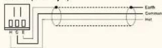
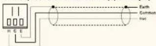
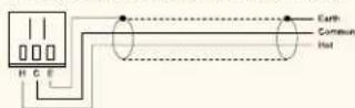
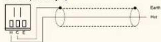
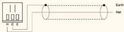
Note: All "S" type modules with 3-screw terminal connectors transitioned to Removable Terminal Block (Phoenix-type) in 2004. Models include: B-01S, B-11S, L-01S, L-11S, L-41S, M-01S, M-11S, M-51S, M-61S, S-01S, S-02S, S-04S, T-01S, U-01S, U-11S, U-12S and U-61S. New Removable Terminal Block (Phoenix-type) connectors have the following pin-out: H: Hot, C: Common, E: Earth
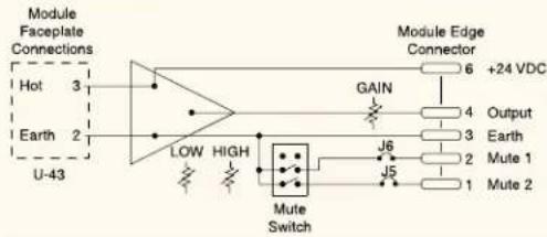
Module Edge Connector
Muting Defined
Muting occurs when one signal source Overrides, or "Mutes", a second signal source. In other words, the first source has Priority over the second source.
For example, a common requirement is for paging to override a music source.
Mute Buses
There are two main types of 900MK2 muting modules - Mute-Receive and Mute-Send.
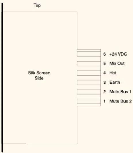
Both types have mute function circuitry that connects to two common "Mute" buses, and one common "Ground" bus when installed in an A-900MK2 mixer/amplifier or M-900MK2 mixer/pre-amplifier. A "Bus" is simply an internal connection from module-slot to module-slot. You can access these buses via rear-panel screw terminals, labeled, "MUTE 1", "MUTE 2" and "GND".
Mute-type modules connect to both mute buses by default. You can disconnect the module's mute function circuitry from each mute bus by cutting jumper wires on the module. This allows you to configure systems with multiple levels of priority.
Mute Function Activation
By default, Mute-Send modules activate both mute buses and Mute-Receive modules respond to both buses.
You can activate the mute bus(es) using either of two methods:
1. Mute-Send
When input signal level to a Mute-Send module exceeds a user-adjustable threshold, the module's mute function circuitry activates the mute function circuitry of all Mute-Receive modules connected to the same bus. This is also referred to as "signal-activated muting" or "auto-muting".
2. Switch Activation
A switch closure between the "Mute (1 or 2)" and "GND" screw terminals on the rear of the mixer/amplifier will activate the mute function circuitry of all Mute-Receive modules connected to the same bus. This is also referred to as "manual muting".
MICROPHONE INPUT MODULES
ML-11T

ML-11T
BLOCK DIAGRAM

flowchart
graph TD
    A["Input"] --> B["MOD"]
    B --> C["OUT"]
    C --> D["OUTPUT"]
    D --> E["ELECTRONE ATTENUATION"]
    E --> F["OUTPUT"]
    F --> G["MOD CIRCUITS"]
    G --> H["MOD OFF"]
    H --> I["MOD OUT"]
    I --> J["MOD OUT"]
    J --> K["MOD OUT"]
    K --> L["MOD OUT"]
    L --> M["MOD OUT"]
    M --> N["MOD OUT"]
    N --> O["MOD OUT"]
    O --> P["MOD OUT"]
    P --> Q["MOD OUT"]
    Q --> R["MOD OUT"]
    R --> S["MOD OUT"]
    S --> T["MOD OUT"]
    T --> U["MOD OUT"]
    U --> V["MOD OUT"]
    V --> W["MOD OUT"]
    W --> X["MOD OUT"]
    X --> Y["MOD OUT"]
    Y --> Z["MOD OUT"]
    Z --> AA["MOD OUT"]
    AA --> AB["MOD OUT"]
    AB --> AC["MOD OUT"]
    AC --> AD["MOD OUT"]
    AD --> AE["MOD OUT"]
    AE --> AF["MOD OUT"]
    AF --> AG["MOD OUT"]
    AG --> AH["MOD OUT"]
    AH --> AI["MOD OUT"]
    AI --> AJ["MOD OUT"]
    AJ --> AK["MOD OUT"]
    AK --> AL["MOD OUT"]
    AL --> AM["MOD OUT"]
    AM --> AN["MOD OUT"]
    AN --> AO["MOD OUT"]
    AO --> AP["MOD OUT"]
    AP --> AQ["MOD OUT"]
    AQ --> AR["MOD OUT"]
    AR --> AS["MOD OUT"]
    AS --> AT["MOD OUT"]
    AT --> AU["MOD OUT"]
    AU --> AV["MOD OUT"]
    AV --> AW["MOD OUT"]
    AW --> AX["MOD OUT"]
    AX --> AY["MOD OUT"]
CONNECTOR DIAGRAM
ML-11T
Microphone/Line Input with Mute Send/Receive
- Switchable Mic/Line Input
- Input Trim and Gain Controls
- Adjustable Mute-Send Threshold (VOX sensitivity)
• High and Low Cut Filters
• Phantom Power, +24 VDC -
VOX Function – Voice-activated mute send operation
• Combination Mute Send and Receive Function -
respond to Mute function of higher priority Mute-Send module(s)
- activate Mute function of lower priority Mute-Receive module(s)
Mute Bus #1 and #2 Connection
• Hysteresis Function ensures smooth muting transitions - Connector: removable terminal block
SPECIFICATIONS
Power Source +24VDC
Current Consumption 25mA
Input 1 channel, -60/-20 dB (changeable), 10k ohms,
unbalanced, removable terminal block (3 pins)
Phantom Power +24VDC
Frequency Response 20 - 20,000 Hz, +1, -1 dB
Distortion 0.05%
Gain 10 - 50 dB
M-01 Series Microphone Input
M-01F

M-01MM-01P

M-01S
(old style)
BLOCK DIAGRAM
M-01S
(new style)
- For Balanced, Low Impedance Microphones.
- High and Low Cut Filters for tone control, 4.2 kHz and 330 Hz, 6 dB/octave.
- Phantom Power, +22 VDC for condenser-type microphones. Active by default, cut Jumper J1 to disable.
- Connectors: female XLR (M-01F), male XLR (M-01M), 1/4" phone jack (M-01P), removable terminal block (M-01S).
SPECIFICATIONS
Faceplate Controls Gain, high & low cut filters
PCB Controls Phantom power defeat
Input Impedance 600 ohms, balanced transformer-isolated
Sensitivity -70 \~ -50 dBu
Gain 32 \~ 52 dB
Noise (EIN) -126 dBu, 200 ohms terminated
CONNECTOR DIAGRAMS
M-01F
M-01M

M-01P

M-01S (old style)
M-01S (new style)
M-11S Microphone Input with Mute-Receive
M-11S (old style)

M-11S (new style)
BLOCK DIAGRAM
CONNECTOR DIAGRAM
M-11S (old style)
M-11S (new style)

- For Balanced, Low Impedance Microphones.
- High and Low Cut Filters for tone control, 4.2 kHz and 330 Hz, 6 dB/octave.
- Phantom Power, +22 VDC for condenser-type microphones. Active by default, cut Jumper J1 to disable.
- Responds To Mute Bus Activation, via Mute SEND module or switch-closure.
- Responds To Both Mute Bus # 1 And Mute Bus # 2 By Default (cut jumper(s) to disconnect individual mute bus).
-
Two Mute Response Modes (cut jumpers to configure):
-
Normally-ON - turns OFF during mute activation (most common)
- Normally-OFF - turns ON during mute activation (functions as an ON/OFF switch, useful for zone-paging microphones in multi-amplifier systems)
Note: Configure the M-11 Mute Response Mode first - it will not pass signal by default. See page 35, Jumper Settings for details.
- Connector: removable terminal block (M-11S).
SPECIFICATIONS
Faceplate Controls Gain, high & low cut filters
PCB Controls Phantom power defeat, mute bus selection
Input Impedance 600 ohms, balanced transformer-isolated
Sensitivity -70 \~ -50 dBu
Gain 32 \~ 52 dB
Noise (EIN) -126 dBu, 200 ohms terminated
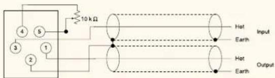
M-21S Microphone Input with Remote Volume Control

M-21S
BLOCK DIAGRAM
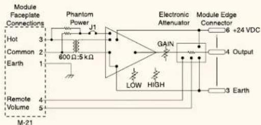
CONNECTOR DIAGRAM
M-21S
• For Balanced, Low Impedance Microphones.
- High and Low Cut Filters for tone control, 4.2 kHz and 330 Hz, 6 dB/octave.
- Phantom Power, +22 VDC for condenser-type microphones. Active by default, cut Jumper J1 to disable.
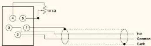
- Remote Volume Control by connecting an external 10 kΩ, linear-taper potentiometer to screw terminals #4 and #5.
Note: Control line resistance greater than 200 Ω will prevent full attenuation (200 Ω = 3821 ft. of #24 AWG wire).
- Tip! You can also connect a switch between screw terminals #4 and #5 for remote on/off operation. Closing the switch turns the module OFF, opening the switch turns the module ON.
- Connector: screw terminal (M-21S).
SPECIFICATIONS
Faceplate Controls Gain, high & low cut filters, terminals for
10 kohm linear-taper pot.
PCB Controls Phantom power defeat
Input Impedance 600 ohms, balanced transformer-isolated
Sensitivity -70 \~ -50 dBu
Gain 32 \~ 52 dB
Noise (EIN) -126 dBu, 200 ohms terminated
M-41S Microphone Input with Mute-Send
M-41S
BLOCK DIAGRAM
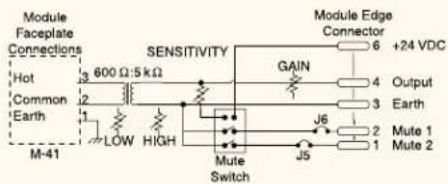
CONNECTOR DIAGRAM
M-41S

- For Balanced, Low Impedance Microphones.
- High and Low Cut Filters for tone control, 4.2 kHz and 330 Hz, 6 dB/octave.
- Phantom Power, +22 VDC for condenser-type microphones. Active by default, cut Jumper J1 to disable.
- Signal At Input Terminals Activates Both Mute Bus # 1 and Mute Bus # 2 by Default (cut jumper(s) to disconnect individual mute bus).
- Connector: removable terminal block (M-41S).
SPECIFICATIONS
Faceplate Controls Gain, high & low cut filters
PCB Controls Mute send sensitivity, phantom power defeat, mute bus selection
Input Impedance 600 ohms, balanced transformer-isolated Sensitivity -69 \~ -45 dBu
Gain 27 \~ 51 dB
Noise (EIN) -124 dBu, 200 ohms terminated
M-51 Series Microphone Input with Voice Gate
M-51F
M-51S (old style)

M-51S (new style)
BLOCK DIAGRAM
CONNECTOR DIAGRAMS
M-51F
- For Balanced, Low Impedance Microphones.
- Low Cut Filter for tone control, 330 Hz, 6 dB/octave.
- Phantom Power, +22 VDC for condenser-type microphones. Active by default, cut Jumper J1 to disable.
- Voice Gate Function, module OFF until input signal exceeds threshold.
- Sensitivity Control - turn clockwise to increase sensitivity (to open gate with lower input signal) and counterclockwise to reduce sensitivity (to open gate with higher input signal).
- Connectors: female XLR (M-51F), removable terminal block (M-51S).
SPECIFICATIONS
Faceplate Controls Gain, low cut filter, voice gate sensitivity PCB Controls Phantom power defeat
Input Impedance 600 ohms, balanced transformer-isolated Sensitivity -70 \~ -50 dBu
Gain 32 \~ 52 dB
Gate Sensitivity -58 dBu \~ always open
Noise (EIN) -126 dBu, 200 ohms terminated
M-51S (old style)
M-51S (new style)
M-61 Series Microphone Input with Compressor

M-61F
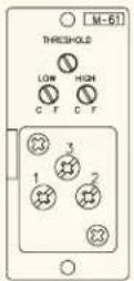
M-61S (old style)
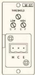
M-61S (new style)
BLOCK DIAGRAM

CONNECTOR DIAGRAMS
M-61F

M-61S (old style)

M-61S (new style)

- For Balanced, Low Impedance Microphones.
- High and Low Cut Filters for tone control, 4.2 kHz and 330 Hz, 6 dB/octave.
- Phantom Power, +22 VDC for condenser-type microphones. Active by default, cut Jumper J1 to disable.
- Compressor Function Helps Prevent Overload And Distortion, activates when the module's input signal exceeds a preset, adjustable threshold.
- Compression Ratio: 2:1 (fixed), reduces the module's output signal level to 1 dB for every 2 dB increase in input signal level.
- Threshold Control - turn CW to lower threshold (to activate compressor function with lower input signal) and CCW to increase threshold (to activate compressor function with higher input signal).
- Connectors: female XLR (M-61F) or removable terminal block (M-61S).
SPECIFICATIONS
Faceplate Controls High and low cut filters, compressor threshold
PCB Controls Phantom power defeat
Input Impedance 600 ohms, balanced transformer-isolated
Sensitivity -70 \~ -50 dBu
Gain 32 \~ 52 dB
Compressor Range 20 dB
Compressor Threshold -64 \~ -44 dBu
Noise (EIN) -126 dBu, 200 ohms terminated
M-03P High Impedance Microphone Input
M-03P
BLOCK DIAGRAM
CONNECTOR DIAGRAM
M-03P
• For Unbalanced, High Impedance Microphones.
- High and Low Cut Filters for tone control, 4.2 kHz and 330 Hz, 6 dB/octave.
- Connector: 1/4" phone jack (M-01P).
SPECIFICATIONS
Faceplate Controls Gain, high & low cut filters
Input Impedance 50 kohms, unbalanced
Sensitivity -60 \~ -40 dBu
Gain 22 \~ 42 dB
Noise (S/N)
70 dB
LINE INPUT MODULES
ML-11T Microphone/Line Input with Mute Send/Receive

ML-11T
BLOCK DIAGRAM

flowchart
graph TD
    A["Input Selection"] --> B["Low High Cut Out Sense"]
    C["Output"] --> D["Electrical Attenuator"]
    B --> E["Logic Circuits"]
    D --> E
    E --> F["Output"]
    style A fill:#f9f,stroke:#333
    style C fill:#f9f,stroke:#333
    style B fill:#ccf,stroke:#333
    style D fill:#ccf,stroke:#333
    style E fill:#cfc,stroke:#333
    subgraph Logic Circuits
        F1["200V"]
        F2["200V"]
        F3["200V"]
        F4["200V"]
        F5["200V"]
        F6["200V"]
        F7["200V"]
        F8["200V"]
        F9["200V"]
        F10["200V"]
        F11["200V"]
        F12["200V"]
        F13["200V"]
        F14["200V"]
        F15["200V"]
        F16["200V"]
        F17["200V"]
        F18["200V"]
        F19["200V"]
        F20["200V"]
        F21["200V"]
        F22["200V"]
        F23["200V"]
        F24["200V"]
        F25["200V"]
        F26["200V"]
        F27["200V"]
        F28["200V"]
        F29["200V"]
        F30["200V"]
        F31["200V"]
        F32["200V"]
        F33["200V"]
        F34["200V"]
        F35["200V"]
        F36["200V"]
        F37["200V"]
        F38["200V"]
        F39["200V"]
        F40["200V"]
        F41["200V"]
        F42["200V"]
        F43["200V"]
        F44["200V"]
        F45["200V"]
        F46["200V"]
        F47["200V"]
        F48["200V"]
        F49["200V"]
        F50["200V"]
        F51["200V"]
        F52["200V"]
        F53["200V"]
        F54["200V"]
        F55["200V"]
        F56["200V"]
        F57["200V"]
        F58["200V"]
        F59["200V"]
        F60["200V"]
CONNECTOR DIAGRAM
ML-11T

- Switchable Mic/Line Input
- Input Trim and Gain Controls
- Adjustable Mute-Send Threshold (VOX sensitivity)
• High and Low Cut Filters
• Phantom Power, +24 VDC -
VOX Function – Voice-activated mute send operation
• Combination Mute Send and Receive Function -
respond to Mute function of higher priority Mute-Send module(s)
- activate Mute function of lower priority Mute-Receive module(s)
- Mute Bus #1 and #2 Connection
• Hysteresis Function ensures smooth muting transitions
- Connector: removable terminal block
SPECIFICATIONS
Power Source +24VDC
Current Consumption 25mA
Input 1 channel, -60/-20 dB (changeable), 10k ohms, unbalanced, removable terminal block (3 pins)
Phantom Power +24VDC
Frequency Response 20 - 20,000 Hz, +1, -1 dB
Distortion 0.05%
Gain 10 - 50 dB
B-01 Series Balanced Line Input
B-01F
B-01S (old style)
B-01S (new style)
BLOCK DIAGRAM

CONNECTOR DIAGRAMS
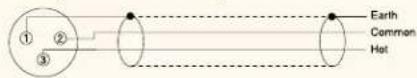
B-01F (Balanced/Unbalanced*)

* For unbalanced sources, use a shielded, twisted pair and connect the output to Hot and Common (inner conductors). Connect the shield to Earth at the module and leave unterminated (floating) at the source.
- For Balanced Or Unbalanced Line Level Sources such as mixer outputs, signal processors and wireless microphone receivers.
- Transformer Isolation (10 kΩ) minimizes ground loop problems when connecting remote equipment (greater than 15 feet). Source output should also be balanced.
- Connector: female XLR (B-01F), removable terminal block (B-01S).
SPECIFICATIONS
Input Impedance 10 kohms, balanced transformer-isolated
Sensitivity -16 dBu
Gain -1 dB
B-01S (Balanced/Unbalanced*) (old style)
B-01S (Balanced/Unbalanced*) (new style)
B-11S Balanced Line Input with Mute-Receive
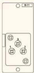
B-11S (old style)
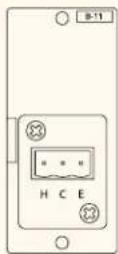
B-11S (new style)
BLOCK DIAGRAM
- For Balanced Or Unbalanced Line Level Sources such as mixer outputs, signal processors and wireless microphone receivers.
- Transformer Isolation minimizes ground loop problems when connecting remote equipment (greater than 15 feet).
- Responds To Mute Bus Activation, via Mute SEND module or switch-closure.
- Responds To Both Mute Bus # 1 And Mute Bus # 2 By Default (cut diode(s) to disconnect individual mute bus).
- Connector: removable terminal block (B-11S).
SPECIFICATIONS
PCB Controls Mute bus selection
Input Impedance 10 kohms, balanced transformer-isolated
Sensitivity -16 dBu
Gain -1 dB
CONNECTOR DIAGRAM
B-11S (Balanced/Unbalanced*) (old style)
B-11S (Balanced/Unbalanced*) (new style)
* For unbalanced sources, use a shielded, twisted pair and connect the output to Hot and Common (inner conductors). Connect the shield to Earth at the module and leave unterminated (floating) at the source.
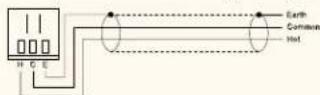
B-21S
Balanced Line Input with Remote Volume Control

B-21S
BLOCK DIAGRAM
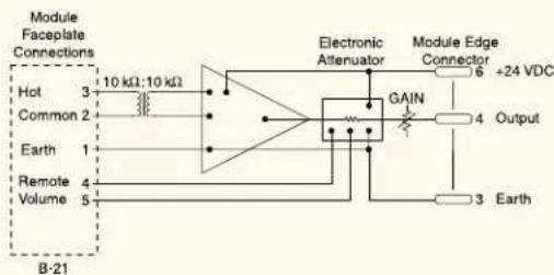
flowchart
graph TD
    A["Hot 3"] --> B["10 kΩ:10 kΩ"]
    C["Common 2"] --> B
    D["Earth 1"] --> B
    E["Remote 4"] --> B
    F["Volume 5"] --> B
    B --> G["Electronic Attenuator"]
    G --> H["Module Edge Connector 6 +24 VDC"]
    H --> I["GAIN"]
    I --> J["Output 4"]
    I --> K["Ground"]
    L["3 Earth"] --> M["Ground"]
- For Balanced Or Unbalanced Line Level Sources such as mixer outputs, signal processors and wireless microphone receivers.
- Transformer Isolation (10 kΩ) minimizes ground loop problems when connecting remote equipment (greater than 15 feet).
- Remote Volume Control by connecting an external 10 kΩ, linear-taper potentiometer to screw terminals #4 and #5.
Note: Control line resistance greater than 200 Ω will prevent full attenuation (200 Ω = 3821 ft. of #24 AWG wire).
- Tip! You can also connect a switch between screw terminals #4 and #5 for remote on/off operation. Closing the switch turns the module OFF, opening the switch turns the module ON.
- Connector: screw terminal (B-21S).
SPECIFICATIONS
Faceplate Controls Gain, terminals for 10 kohm linear-taper pot.
Input Impedance 10 kohms, balanced transformer-isolated
Sensitivity -16 \~ +14 dBu
Gain -32 \~ -2 dB
CONNECTOR DIAGRAM
B-21S (Balanced/Unbalanced*)

* For unbalanced sources, use a shielded, twisted pair and connect the output to Hot and Common (inner conductors). Connect the shield to Earth at the module and leave unterminated (floating) at the source.
B-41S Balanced Line Input with Mute-Send

B-41S
BLOCK DIAGRAM

CONNECTOR DIAGRAM
B-41S (Balanced/Unbalanced*)

- For Balanced Or Unbalanced Line Level Sources such as mixer outputs, signal processors and wireless microphone receivers.
- Transformer Isolation (10 kΩ) minimizes ground loop problems when connecting remote equipment (greater than 15 feet).
- Signal At Input Terminals Activates Both Mute Bus # 1 and Mute Bus # 2 by Default (cut diode(s) to disconnect individual mute bus).
- Tip! Use the B-41S to connect to most modern telephone system's "Page Output" (usually line level).
- Connector: removable terminal block (B-41S).
SPECIFICATIONS
Faceplate Controls Mute send sensitivity
PCB Controls Mute bus selection
Input Impedance 10 kohms, balanced transformer-isolated
Sensitivity -16 dBu, min. -34 dBu to activate mute function
Gain -2 dB
* For unbalanced sources, use a shielded, twisted pair and connect the output to Hot and Common (inner conductors). Connect the shield to Earth at the module and leave unterminated (floating) at the source.
IMPEDANCE MATCHING
Most modern audio devices have LOW Impedance outputs which are designed to drive HIGH Impedance inputs. This results in Maximum Voltage Transfer - almost all of the output's signal voltage is transferred to the input. This is also referred to as a Bridged connection.
Impedance matching (output impedance to input impedance) results in Maximum Power Transfer and causes approximately 6 dB of signal voltage loss. This often exceeds the source device's "minimum load impedance" specification causing distortion or, at worst, damage to the source's output circuitry.
Maximum Voltage Transfer occurs when input impedance equals at least ten times the source device's output impedance.
For example, if the source's output impedance equals 600 Ω, the input impedance of the next device should equal at least 6 kΩ or greater.
Tip! You can convert the input impedance of an "L" module to 10 kΩ by locating and cutting "R1" (680 Ω) on the module PCB. This will result in approximately 6 dB of additional gain, assuming the source's output impedance is 600 Ω.
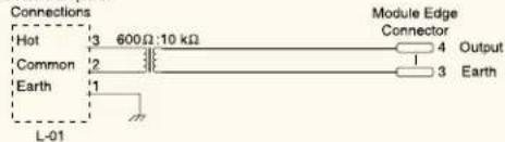
L-01 Series Line Matching Input

L-01F

L-01S (old style)
L-01S (new style)
BLOCK DIAGRAM
Module Faceplate
CONNECTOR DIAGRAMS
L-01F (Balanced/Unbalanced*)
* For unbalanced sources, use a shielded, twisted pair and connect the output to Hot and Common (inner conductors). Connect the shield to Earth at the module and leave unterminated (floating) at the source.
• For Applications Requiring 600 Ohm Line Matching.
- Transformer Isolation (600 Ω) minimizes ground loop problems when connecting remote equipment (greater than 15 feet).
- Connector: removable terminal block (L-01S).
SPECIFICATIONS
Input Impedance 600 ohms, balanced transformer-isolated
Sensitivity -16 dBu
Gain -2 dB
L-01S (Balanced/Unbalanced*) (old style)
L-01S (Balanced/Unbalanced*) (new style)
L-11S
L-11S (old style)

L-11S (new style)
BLOCK DIAGRAM
CONNECTOR DIAGRAM
L-11S (Balanced/Unbalanced*) (old style)
L-11S (Balanced/Unbalanced*) (new style)
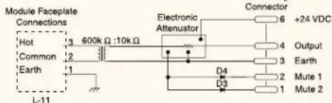
Line Matching Input with Mute-Receive
- For Applications Requiring 600 Ohm Line Matching.
- Transformer Isolation (600 Ω) minimizes ground loop problems when connecting remote equipment (greater than 15 feet).
- Responds To Mute Bus Activation, via Mute SEND module or switch-closure.
- Responds To Both Mute Bus # 1 And Mute Bus # 2 By Default (cut diode(s) to disconnect individual mute bus)
- Connector: removable terminal block (L-11S).
SPECIFICATIONS
PCB Controls Mute bus selection
Input Impedance 600 ohms, balanced transformer-isolated Sensitivity -16 dBu
Gain -1 dB
* For unbalanced sources, use a shielded, twisted pair and connect the output to Hot and Common (inner conductors). Connect the shield to Earth at the module and leave unterminated (floating) at the source.
L-41S Line Matching Input with Mute-Send
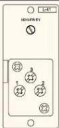
L-41S (old style)

L-41S (new style)
BLOCK DIAGRAM

- For Applications Requiring 600 Ohm Line Matching.
- Transformer Isolation (600 Ω) minimizes ground loop problems when connecting remote equipment (greater than 15 feet).
- Signal At Input Terminals Activates Both Mute Bus # 1 and Mute Bus # 2 Buses by Default (cut diode(s) to disconnect individual mute bus).
- Connector: removable terminal block (L-41S).
SPECIFICATIONS
Faceplate Controls Mute send sensitivity
PCB Controls Mute bus selection
Input Impedance 600 ohms, balanced transformer-isolated
Sensitivity -16 dBu, min. -34 dBu to activate mute
function
Gain -2 dB
CONNECTOR DIAGRAM
L-41S (Balanced/Unbalanced*) (old style)
L-41S (Balanced/Unbalanced*) (new style)
* For unbalanced sources, use a shielded, twisted pair and connect the output to Hot and Common (inner conductors). Connect the shield to Earth at the module and leave unterminated (floating) at the source.
UNBALANCED LINE INPUT
Sources with unbalanced outputs should always be located adjacent to the mixer/amplifier (less than 15 feet). If the source is located further than 15 feet, convert the unbalanced output to
balanced with an appropriate transformer (available from other vendors) and connect to a B or M module, depending on the signal level.
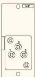
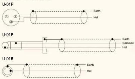
U-01 Series Unbalanced Line Input
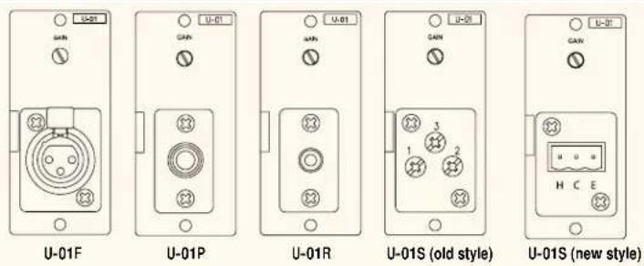
BLOCK DIAGRAM

- For Unbalanced, Line Level Sources such as AM/FM tuners, cassette decks, CD players, computer sound cards, jukeboxes, mixers and satellite receivers.
- Use For Adjacent Sources (less than 15 feet from the host unit).
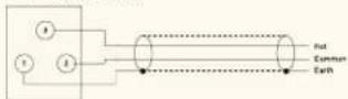
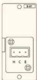
- Connectors: female XLR (U-01F), 1/4" phone jack (U-01P), RCA jack (U-01R), removable terminal block (U-01S).
SPECIFICATIONS
Faceplate Controls Gain
Input Impedance 220 kohms, unbalanced
Sensitivity -18 \~ +12 dBu
Gain -30 \~ 0 dB
Noise (S/N) 90 dB
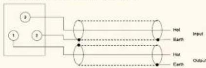
CONNECTOR DIAGRAMS
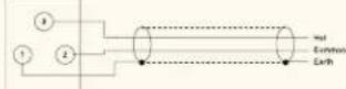
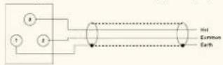
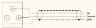
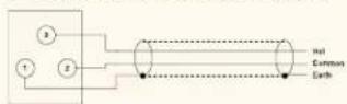
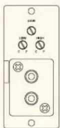
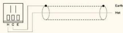
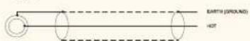
U-01S (old style)
flowchart
graph TD
    A["1"] --> B["2"]
    C["3"] --> B
    B --> D["Hot"]
    B --> E["Earth"]
U-01S (new style)

U-03 Series Unbalanced Line Input with High/Low Cut Filters

BLOCK DIAGRAM

- For Unbalanced, Line Level Sources such as AM/FM tuners, cassette decks, CD players, computer sound cards, jukeboxes, mixers and satellite receivers.
- Use For Adjacent Sources (less than 15 feet from the host unit).
- High and Low Cut Filters for tone control, 4.2 kHz and 330 Hz, 6 dB/octave.
- Connectors: dual RCA jack w/ passive summing (U-03R), removable terminal block (U-03S).
SPECIFICATIONS
Faceplate Controls Gain, high & low cut filters
Input Impedance 220 kohms, unbalanced
Sensitivity -17 \~ +13 dBu
Gain -30 \~ -1 dB
Noise (S/N) 85 dB
CONNECTOR DIAGRAMS
U-03R
U-03S

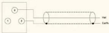
U-11 Series Unbalanced Line Input with Mute-Receive
BLOCK DIAGRAM

flowchart
graph TD
    A["Module Faceplate Connections"] --> B["Hot 3"]
    A --> C["Earth 2"]
    A --> D["U-11"]
    B --> E["Op-Amp"]
    C --> E
    E --> F["GAIN"]
    F --> G["Output 4"]
    G --> H["Module Edge Connector 6 +24 VDC"]
    H --> I["+24 VDC"]
    J["Ground"] --> K["3 Earth"]
    J --> L["2 Mute 1"]
    J --> M["1 Mute 2"]
    N["J5"] --> O["J6"]
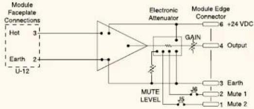
- For Unbalanced, Line Level Sources such as AM/FM tuners, cassette decks, CD players, computer sound cards, jukeboxes, mixers and satellite receivers.
- Use For Adjacent Sources (less than 15 feet from the host unit).
- Responds To Mute Bus Activation, via Mute SEND module or switch-closure.
- Responds To Both Mute Bus # 1 And Mute Bus # 2 By Default (cut jumper(s) to disconnect individual mute bus).
- Connectors: RCA jack (U-11R), removable terminal block (U-11S).
SPECIFICATIONS
Faceplate Controls Gain
PCB Controls Mute bus selection
Input Impedance 220 kohms, unbalanced
Sensitivity -18 \~ +12 dBu
Gain -30 \~ 0 dB
Noise (S/N) 90 dB
CONNECTOR DIAGRAMS
U-11R
U-11S (old style)

U-11S (new style)
U-12S Unbalanced Line Input with Variable Mute-Receive Depth

U-12S (old style)
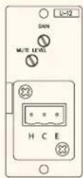
U-12S (new style)
BLOCK DIAGRAM
- For Unbalanced, Line Level Sources such as AM/FM tuners, cassette decks, CD players, computer sound cards, jukeboxes, mixers and satellite receivers.
- Use For Adjacent Sources (less than 15 feet from the host unit).
- Responds To Mute Bus Activation, via Mute SEND module or switch-closure.
- Responds To Both Mute Bus # 1 And Mute Bus # 2 By Default (cut jumper(s) to disconnect individual mute bus).
- Adjustable Mute Depth Provides Ducking Rather Than Full Muting.
- Connector: removable terminal block (U-12S).
SPECIFICATIONS
Faceplate Controls Gain, muting depth
PCB Controls Mute bus selection
Input Impedance 220 kohms, unbalanced
Sensitivity -18 \~ +12 dBu
Gain -30 \~ 0 dB
Muting Depth -60 \~ 0 dB
Noise (S/N) 90 dB
CONNECTOR DIAGRAM
U-12S (old style)

U-12S (new style)
U-13 Series Unbalanced Line Input with High/Low Cut Filters and Mute-Receive
U-13R
U-13S
BLOCK DIAGRAM

- For Unbalanced, Line Level Sources such as AM/FM tuners, cassette decks, CD players, computer sound cards, jukeboxes, mixers and satellite receivers.
- Use For Adjacent Sources (less than 15 feet from the host unit).
- High and Low Cut Filters for tone control, 4.2 kHz and 330 Hz, 6 dB/octave.
- Responds To Mute Bus Activation, via Mute SEND module or switch-closure.
- Responds To Both Mute Bus # 1 And Mute Bus # 2 By Default (cut jumper(s) to disconnect individual mute bus).
- Connectors: dual RCA jacks w/ passive summing (U-13R), removable terminal block (U-13S).
SPECIFICATIONS
Faceplate Controls Gain, high & low cut filters
PCB Controls Mute bus selection
Input Impedance 220 kohms, unbalanced
Sensitivity -17 \~ +13 dBu
Gain -30 \~ -1 dB
Noise (S/N) 85 dB
CONNECTOR DIAGRAMS
U-13R
flowchart
graph LR
    A["Left"] --> B["Hot"]
    C["Right"] --> D["Hot"]
    style A fill:#f9f,stroke:#333
    style C fill:#f9f,stroke:#333
U-13S
U-14R Dual Input Priority w/AGC and Mute-Receive
U-14R
BLOCK DIAGRAM

flowchart
graph TD
    A["Module Forward Connections"] --> B["RAM"]
    A --> C["LIME"]
    B --> D["5 OUTR/T"]
    C --> E["2 MUTE 1"]
    D --> F["4 OUTR/T"]
    E --> G["1 MUTE 2"]
    H["Ground"] --> I["Ground"]
    J["Ground"] --> K["Ground"]
    L["Ground"] --> M["Ground"]
    N["Ground"] --> O["Ground"]
    P["Ground"] --> Q["Ground"]
    R["Ground"] --> S["Ground"]
    T["Ground"] --> U["Ground"]
    V["Ground"] --> W["Ground"]
    X["Ground"] --> Y["Ground"]
    Z["Ground"] --> AA["Ground"]
CONNECTOR DIAGRAM
U-14R
- Dual Input Module for applications with business music plus an on-premises CD jukebox or other source
- Two Line Inputs – Jukebox and BGM
- Auto-Mute Function with adjustable Mute threshold (Jukebox overrides BGM)
• Automatic Gain Control (AGC) on Jukebox input for consistent signal levels
• Individual Input Level Controls - Connector: Stereo-Summing Dual RCA Jacks
- Mute-Receive Function – Cut jumper(s) to disable Mute 1 or Mute 2
SPECIFICATIONS
Input 47k ohms (unbalanced)
Maximum Output
Frequency Response
Distortion
Output Level Var. Range
+14 dBV (5 Vrms)
20 - 20.000 Hz, +1, -1 dB
BGM: 0.03% (1 kHz, 1 Vrms)
JUKE: 0.05% (1 kHz, 1 Vrms)
BGM: -24 to -4 dBV (-10 dBV
input to L and R
JUKE: -24 to -4 dBV (-10 dBV
input to L and R)
JUKE Gate Threshold Level Var. Range -60 to -30 dB (input to L and R)
U-21S Unbalanced Line Input with Remote Volume Control
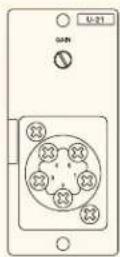
U-21S
BLOCK DIAGRAM
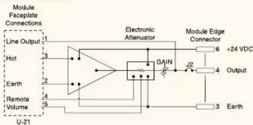
flowchart
graph TD
    A["Module Faceplate Connections"] --> B["Line Output"]
    A --> C["Hot"]
    A --> D["Earth"]
    A --> E["Remote Volume"]
    A --> F["U-21"]
    B --> G["Electronic Attenuator"]
    C --> G
    D --> G
    E --> G
    F --> G
    G --> H["GAIN"]
    H --> I["Module Edge Connector"]
    I --> J["+24 VDC"]
    I --> K["Output"]
    I --> L["3 Earth"]
CONNECTOR DIAGRAMS
U-21S

U-21S (Master Volume)
- For Unbalanced, Line Level Sources such as AM/FM tuners, cassette decks, CD players, computer sound cards, jukeboxes, mixers and satellite receivers.
- Use For Adjacent Sources (less than 15 feet from the host unit).
- Remote Volume Control by connecting an external 10 kΩ, linear-taper potentiometer to screw terminals #4 and #5.
- Tip! You can also connect a switch between screw terminals #4 and #5 for remote on/off operation. Closing the switch turns the module OFF, opening the switch turns the module ON.
Note: Control line resistance greater than 200 Ω will prevent full attenuation (200 Ω = 3821 ft. of #24 AWG wire). - Tip! You can also use the U-21 as a stand-alone Remote Volume control by cutting Jumper J2 to disconnect the module's output from the mix bus. This function is useful in original 900 Series mixer/amplifiers which did not have built-in Remote Master Volume terminals or, as a second Remote Master Volume for the A-903/6/12MK2 mixer/amplifiers, the AX-1000A auto-mixer or the M-900MK2 mixer/pre-amplifier. Connect the module input to the "Pre-Out" jack (or mixer output) and the module output to the "Power-In" jack (or adjacent power amplifier).
- Connector: screw terminal (U-21S).
SPECIFICATIONS
Faceplate Controls Gain, terminals for 10 kohm linear-taper pot.
Input Impedance 220 kohms, unbalanced
Sensitivity -18 \~ +12 dBu
Gain -30 \~ 0 dB
Noise (S/N) 90 dB
U-43 SERIES Unbalanced Line Input with High/Low Cut Filters and Mute-Send
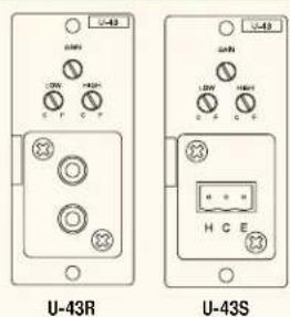
BLOCK DIAGRAM
CONNECTOR DIAGRAMS
U-43R
U-43S
- For Unbalanced, Line Level Sources such as AM/FM tuners, cassette decks, CD players, computer sound cards, jukeboxes, mixers and satellite receivers.
- Use For Adjacent Sources (less than 15 feet from the host unit).
- High and Low Cut Filters for tone control, 4.2 kHz and 330 Hz, 6 dB/octave.
- Signal At Input Terminals Activates Both Mute Bus # 1 and Mute Bus # 2 by Default (cut jumper(s) to disconnect individual mute bus).
- Connectors: dual RCA jacks w/ passive summing (U-43R), removable terminal block (U-43S).
SPECIFICATIONS
Faceplate Controls Gain, high & low cut filters
PCB Controls Mute send sensitivity, mute bus selection
Input Impedance 220 kohms, unbalanced
Sensitivity -17 \~ +13 dBu
Gain -30 \~ -1 dB
Noise (S/N) 85 dB
U-61S Unbalanced Line Input with Compressor
U-61S (old style)
U-61S (new style)
BLOCK DIAGRAM

flowchart
graph LR
    A["Line Out 1"] --> B["Hot 3"]
    A --> C["Earth 2"]
    B --> D["Electronic Attenuator"]
    C --> D
    D --> E["GAIN"]
    E --> F["J2"]
    F --> G["Output 4"]
    G --> H["Module Edge Connector 6 +24 VDC"]
    H --> I["3 Earth"]
    J["U-61"] --> D
CONNECTOR DIAGRAMS
U-61S (old style)
flowchart
graph TD
    A["①"] --> C["Hot"]
    B["②"] --> C["Hot"]
    C --> D["Earth"]
U-61S (Master Compressor - old style)
flowchart
graph TD
    A["Component 1"] --> B["Component 2"]
    B --> C["Output"]
    D["Hot"] --> E["Input"]
    F["Earth"] --> G["Input"]
    H["Hot"] --> I["Output"]
U-61S (new style)
U-61S (Master Compressor - new style)

- For Unbalanced, Line Level Sources such as AM/FM tuners, cassette decks, CD players, computer sound cards, jukeboxes, mixers and satellite receivers.
- Use For Adjacent Sources (less than 15 feet from the host unit).
- Compressor Function Helps Prevent Overload And Distortion, activates when the module's input signal exceeds a preset, adjustable threshold.
- Compression Ratio: 2:1 (fixed) reduces the module's output signal level to 1 dB for every 2 dB increase in input signal level.
- Tip! You can also use the U-61 as a standalone Compressor or Master Compressor by cutting Jumper J2 to disconnect the module's output from the mix bus. Connect the "Pre-Out" jack (or mixer output) to the module input and the "Power-In" jack (or adjacent power amplifier) to the module output.
- Connector: removable terminal block (U-61S).
SPECIFICATIONS
Faceplate Controls Gain
Input Impedance 220 kohms, unbalanced
Sensitivity -18 \~ +12 dBu
Gain -30 \~ 0 dB
Compressor Range 20 dB
Compressor Threshold +2 dBu
Noise (S/N) 90 dB
SPECIAL FUNCTION MODULES
T-01S Balanced Line Output
T-01S (old style)

T-01S (new style)
BLOCK DIAGRAM
- Transformer-Isolated Line Output of the mixing bus signal to feed other remote mixers, amplifiers, and tape recorders.
- Note: Functions only in specific models - see page 33, Modular Products chart.
- Tip! You can use multiple T-01's to create a distribution amplifier for large multi-amplifier systems, media feeds, recording, etc.
- Connector: removable terminal block (T-01S).
SPECIFICATIONS
Faceplate Controls Output gain
Gain 4 \~ 20 dB
Output
Balanced transformer-isolated,drives
loads ≥ 600 ohms,+15 dBu max.
Noise (S/N) 80 dB
CONNECTOR DIAGRAMS
T-01S (Balanced/Unbalanced) (old style)

T-01S (Balanced/Unbalanced) (new style)

T-02S Unbalanced Line Input with Music-On-Hold Output
T-02S
BLOCK DIAGRAM
- Unbalanced Line Input for AM/FM tuners, cassette decks, CD players, computer sound cards, jukeboxes, mixers and satellite receivers.
- Balanced, Uninterrupted Output Of Module's Input Signal, transformer-isolated for feeding remote equipment such as a telephone system's Music-On-Hold input.
- Output Gain Control for adjusting the MOH output signal level, eliminating the need for an external 1 Watt MOH amplifier.
- Connector: screw terminal (T-02S).
SPECIFICATIONS
Faceplate Controls Input gain, output gain
Input Impedance 220 kohms, unbalanced
Slave Output Balanced transformer-isolated.drives
loads ≥ 600 ohms,+16 dBu max.
Sensitivity -18 \~ +2 dBu
Gain Mix bus: -20 \~ 0 dB / slave: 4 \~ 20 dB
Noise (S/N) Mix bus: 90 dB / slave: 80 dB
CONNECTOR DIAGRAM
T-02S (Balanced/Unbalanced Output)

flowchart
graph TD
    A["4"] --> B["1"]
    C["5"] --> B
    D["3"] --> B
    E["2"] --> B
    B --> F["Hot"]
    B --> G["Earth"]
    H["1"] --> I["Common"]
    J["2"] --> I
    I --> K["Hot"]
    I --> L["Output"]
    style A fill:#f9f,stroke:#333
    style C fill:#f9f,stroke:#333
    style E fill:#f9f,stroke:#333
    style F fill:#fff,stroke:#333
    style G fill:#fff,stroke:#333
    style H fill:#fff,stroke:#333
    style I fill:#fff,stroke:#333
    style J fill:#fff,stroke:#333
T-12S Unbalanced Line Input with Music-On-Hold Output & Input Mute-Receive
T-12S
BLOCK DIAGRAM
flowchart
graph TD
    A["Hot"] --> B["600 Ω-600 Ω"]
    C["Common"] --> B
    D["Earth"] --> B
    E["Common"] --> B
    F["Line out"] --> B
    B --> G["OUTPUT"]
    G --> H["GAIN"]
    H --> I["Electronic Attenuator"]
    I --> J["Module Edge Connector"]
    J --> K["6 +24 VDC"]
    J --> L["4 Output"]
    J --> M["3 Earth"]
    J --> N["2 Mute 1"]
    J --> O["1 Mute 2"]
    P["T-12"] --> Q["Output"]
    R["Electronic Attenuator"] --> S["600 Ω-600 Ω"]
    T["Electronic Attenuator"] --> U["600 Ω-600 Ω"]
    V["Electronic Attenuator"] --> W["600 Ω-600 Ω"]
CONNECTOR DIAGRAM
T-12S (Balanced/Unbalanced Output)
flowchart
graph TD
    A["4"] --> B["1"]
    C["5"] --> B
    D["3"] --> B
    E["2"] --> B
    B --> F["Hot"]
    B --> G["Earth"]
    H["Input"] --> I["Output"]
    J["Common"] --> K["Output"]
- Unbalanced Line Input for for AM/FM tuners, cassette decks, CD players, computer sound cards, jukeboxes, mixers and satellite receivers.
- Balanced, Uninterrupted Output Of Module's Input Signal, transformer-isolated for feeding remote equipment such as a telephone system's Music-On-Hold input.
- Output Gain Control for adjusting the MOH output signal level, eliminating the need for an external 1 Watt MOH amplifier.
- Responds To Mute Bus Activation, via Mute SEND module or switch-closure.
- Responds To Both Mute Bus # 1 And Mute Bus # 2 By Default (cut jumper(s) to disconnect individual mute bus).
- Tip! You can pair the T-12S with the B-41S Mute-Send module for telephone paging, mutable music input, and uninterrupted MOH output, all with only two modules.
- Connector: screw terminal (T-12S).
SPECIFICATIONS
Faceplate Controls Input gain, output gain
PCB Controls Mute bus selection
Input Impedance 220 kohms, unbalanced
Slave Output: Balanced transformer-isolated, drives
loads ≥ 600 ohms,+16 dBu max.
Sensitivity -18 \~ 0 dBu
Gain Mix bus: -18 \~ 0 dB / slave: 4 \~ 20 dB
Noise (S/N) Mix bus: 85 dB / slave: 85 dB
SPECIAL FUNCTION MODULES: TONE GENERATOR
S-20S Digital Message/Tone w/USB and Mute-Send

S-20S
BLOCK DIAGRAM

flowchart
graph TD
    A["Module Faceplate Connections"] --> B["VO"]
    B --> C["T"]
    B --> D["G"]
    B --> E["FE"]
    C --> F["MEMORY"]
    D --> F
    E --> F
    F --> G["DAC"]
    G --> H["MUTE SEND"]
    H --> I["1.5F2"]
    I --> J["MUTE OFF"]
    K["Module Edge Connector"] --> L["10 MID1"]
    K --> M["9 MID0"]
    K --> N["7 BUSY"]
    K --> O["6 +24VDC"]
    K --> P["4 OUTPUT"]
    K --> Q["3 EARTH"]
    K --> R["2 MUTE 1"]
CONNECTOR DIAGRAM
S-20S
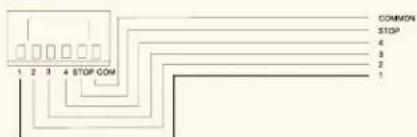
- Digital Audio Storage Module for messaging and tone-signaling applications
- USB Interface for fast audio file transfer between PC and module
- Three Minutes of CD Quality Digital Storage – 50 to 20k Hz frequency response
• Versatile CD-ROM Tone Library included - Accepts Four Audio Files – 44.1 kHz, 16 bit PCM WAV format
• External Activation for single or continuous playback
• Automatic Priority overrides current message - Stop Function immediately cancels playback
- Selectable Playback Interval for each message
• Auto-Mute Function for priority over background music - Adjustable Level Control
- USB Cable Included
SPECIFICATIONS
File Format
Frequency Response 50
Distortion
Recording System
Control Inputs
44.1 kHz sampling frequency, 16-bit PCM WAV (monaural)
20.000 Hz +/- 3 dB (1 kHz)
Under 1% (1 kHz)
USB data transfer
Playback 1-4, Stop: No voltage make contact input,
pulse make length: 200ms, open circuit voltage:
24 VDC, short circuit current: 2mA, removable
terminal block (6 pins)
1
3 minutes (180 seconds)
Continuous, 0/5/10/30 seconds, 1/5/10/30 mins..
1 hour (selectable for each message)
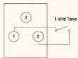
S-01S 1 kHz Sine Wave Test Tone
S-01S (old style)

S-01S (new style)
BLOCK DIAGRAM

flowchart
graph LR
    A["Module Faceplate Connections"] --> B["Signal Generator"]
    C["Common"] --> B
    B --> D["Module Edge Connector"]
    D --> E["+24 VDC"]
    D --> F["Output"]
    D --> G["Earth"]
    H["S-01"] --> I["1 kHz"]
    H --> J["1 kHz"]
    H --> K["Common"]
    L["GAIN"] --> M["Ground"]
CONNECTOR DIAGRAM
S-01S (old style)
S-01S (new style)

- 1 kHz Test Tone, activates with a switch closure (short-circuit) across module screw terminals #2 and #1.
- Connector: removable terminal block (S-01S).
SPECIFICATIONS
Faceplate Controls Gain, terminals for triggering tone
Gain Off \~ 0 dB
Noise (S/N) 80 dB
Available Tone 1 kHz sine wave
S-02S Buzzer/Yelp Tone
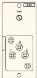
S-02S (old style)
S-02S (new style)
BLOCK DIAGRAM

CONNECTOR DIAGRAM
S-02S (old style)

flowchart
graph TD
    A["Yelp Signal"] --> B["3"]
    B --> C["1"]
    B --> D["2"]
    E["Buzzer Signal"] --> F["0"]
S-02S (new style)

- "Buzzer" Tone activates with a switch closure (short-circuit) across module screw terminals #2 and #1.
- "Yelp" Tone activates with a switch closure (short-circuit) across module screw terminals #3 and #1.
- Continuous Tone Activation for the duration of the switch closure.
- Connector: removable terminal block (S-02S).
SPECIFICATIONS
Faceplate Controls Gain, terminals for triggering buzzer and yelp tones
Gain Off \~ 0 dB
Noise (S/N) 80 dB
Available Tones Buzzer, yelp
S-04S Switch-Selectable Tone
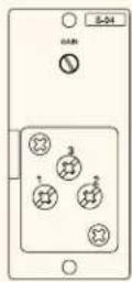
S-04S (old style)
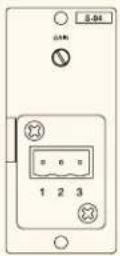
S-04S (new style)
BLOCK DIAGRAM

CONNECTOR DIAGRAM
S-04S (old style)
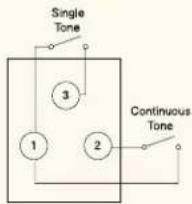
flowchart
graph TD
    A["Single Tone"] --> B["Node 3"]
    B --> C["Node 1"]
    B --> D["Node 2"]
    E["Continuous Tone"] --> F["Node 2"]
S-04S (new style)

- Eight Available Tones, selected via DIP switches.
- Single Tone Activation with a switch closure (short-circuit) across module screw terminals #3 and #1.
- Continuous Tone Activation with a switch closure (short-circuit) across module screw terminals #2 and #1.
- Applications: doorbell, paging, door/gate release, telephone night ringer, annunciator, class change or pre-announcement tone.
- Connector: removable terminal block (S-04S).
SPECIFICATIONS
Faceplate Controls Gain, terminals to trigger tones (single or repeated)
PCB Controls Dip switch for selecting among 8 tones
Gain Off \~ 0 dB
Noise (S/N) 80 dB
Available Tones 1 tone chime, 2 tone chime, 4 tone chime up, 4 tone chime down, gong, Westminster, holding tone 1, holding tone 2
DIP Switch Settings
| S1 | S2 | S3 | Tone |
| On On On 4 tone chime (up) | |||
| Off On On 2 tone chime | |||
| On Off On Gong | |||
| Off Off On Westminster chime | |||
| On On Off 1 tone chime | |||
| Off On Off Hold 1 | |||
| On Off Off Hold 2 | |||
| Off Off Off 4 tone chime (down) | |||
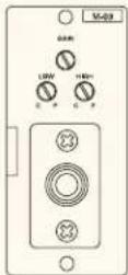
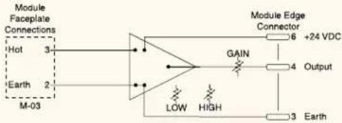
SPECIAL FUNCTION MODULES: VOLUME CONTROL
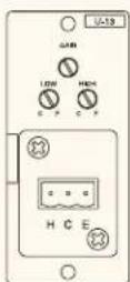
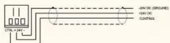
V-01S Remote Master Volume Control (VCA)

V-01S
BLOCK DIAGRAM

flowchart
graph TD
    A["IN"] --> B["Ground"]
    C["OUT"] --> D["Ground"]
    E["HOT"] --> F["Ground"]
    G["CTRL"] --> H["-24V DC"]
    I["24V DC (GROUND)"] --> J["VOLTAGE CONTROLLED ATTENUATOR"]
    K["3 EARTH (GROUND)"] --> L["Module Edge Connector 6 -34VDC"]
CONNECTOR DIAGRAM
V-01S
- Voltage Controlled Amplifier (VCA) for applications requiring preset remote master volume control
- Line Input and Output connect to host amplifier's pre-amp output and power amp input
- 24 VDC Output and Control Input interfaces directly to RDL RLC3 Remote Level Control
- Connectors: RCA and removable terminal block
SPECIFICATIONS
Input
10k ohms (unbalanced)
Max. Allowable Input
-14 dBV (5 Vrms)
Frequency Response
20 - 20,000 Hz +/- 1 dB
Distortion
0.03% (1 kHz, 1 Vrms)
S-04 —
V-01
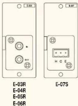
E Series Processor Modules for TOA Speakers
BLOCK DIAGRAM

CONNECTOR DIAGRAM
- Optimized Equalization Curve For TOA Speakers (see chart).
- Connects Between 900MK2 Mixer/Amplifier's "Pre-Out" And "Power-In" Jacks or Between Separate Mixer and Amplifier (E-03R – E-06R).
• Includes Dual RCA Cable. - Unbalanced Input and Output (see Figure 1).
- Connector: dual RCA jack, removable terminal block (E-07S).
Connection Methods:
A-903MK2, A-906MK2, A-912MK2 Mixer/Amplifiers
- Connect the "Pre-amp Out" jack to the E module's "In" jack and the E module's "Out" jack to the "Power Amp In" jack (Figure 2).
M-900MK2 Mixer/Pre-amplifier
- Connect the "Aux. Output" jack to the E module's "In" jack and the E module's "Out" jack to the input of an adjacent power amplifier such as the TOA P-900MK2 Series (Figure 3).
P-906MK2, P-912MK2, P-924MK2 Power Amplifiers
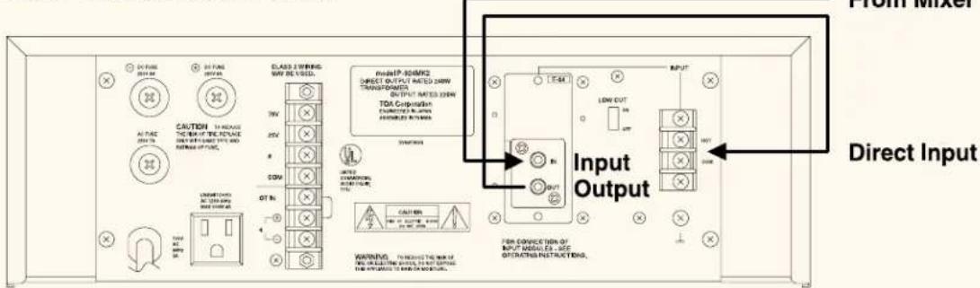
- Connect the mixer output to the E module's "In" jack and the "Out" jack to the amplifier's "Direct Input" screw terminals (Figure 4).
- Note: Since the E module's jacks are unbalanced, install external devices adjacent to the module. If the device is located further than 15 feet, convert all inputs and outputs to balanced with appropriate transformers (available from other vendors).
SPECIFICATIONS (E-03R - E-06R)
Input Impedance 100 kohms, unbalanced
Output Impedance 1 kohms, unbalanced
Sensitivity +2.2 dBu
Output Level +2.2 dBu
Noise (S/N) 86 dB
Modules & Corresponding Speakers
| Module: Speaker: |
| E-03R F-122CU/CU2 |
| E-04R H-1 |
| E-05R H-2/H-2WP |
| E-06R H-3/H-3WP |
| E-07S FB-100/HB-1 |
E Series Processor Modules for TOA Speakers
Figure 1 - E Module Signal Flow (E-03R - E-06R)
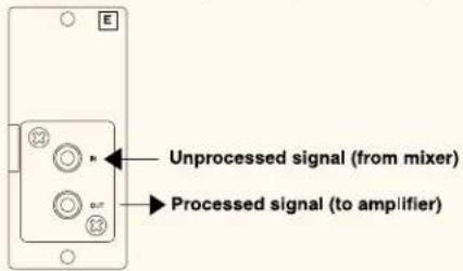
Figure 2 - E Module Connection in A-900MK2
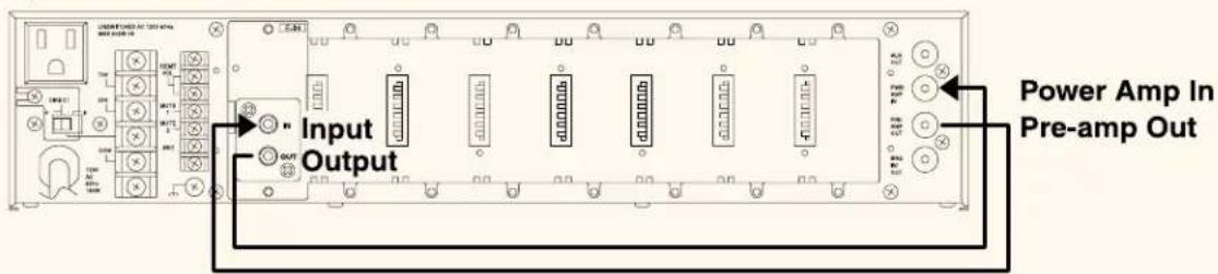
Figure 3 - E Module Connection in M-900MK2 and P-924MK2
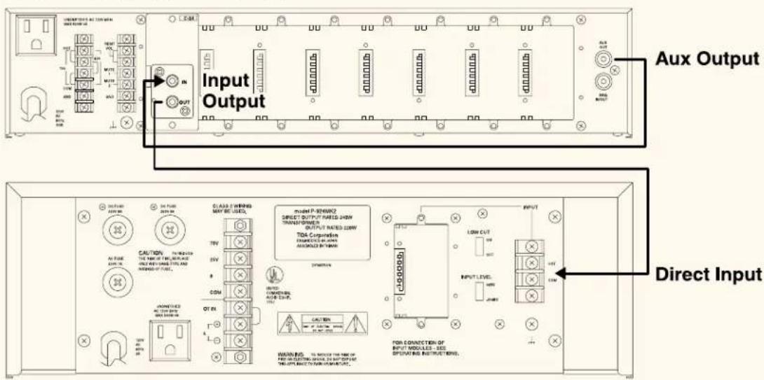
Figure 4 - E Module Connection in P-900MK2
APPLICATIONS
Paging Over a Music Source
- Connect the Telephone Page output to a B-41S (Balanced Line Input with Mute-Send) module or, for Microphone Paging, use an M-41S (Microphone Input with Mute-Send) module.
- Connect the Music Source to a U-13R (Unbalanced Line Input with Mute-Receive) module.
- Adjust the mute threshold as necessary with the Sensitivity control (located on the mute-send module's circuit board). If the paging audio falls below the mute threshold for greater than approximately two seconds, the music will resume.
Since mute-type modules connect to both Mute Bus #1 and #2 by default, no jumper configuration is required.
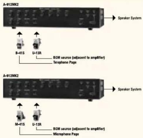
Telephone Paging and Music-On-Hold
- Connect the Telephone Page output to a B-41S (Balanced Line Input with Mute-Send) module.
- Connect the Music Source to a T-12S (Unbalanced Line Input with Music-On-Hold Output) module's input.
- Connect the T-12S module's output to the telephone system's Music-On-Hold input.
- Adjust the output signal level with the T-12S front panel Output Gain control.
Since mute-type modules connect to both Mute Bus #1 and #2 by default, no jumper configuration is required.

Banquet Room Sound System
Banquet room sound systems usually include a podium microphone and a music source. Since there will be a variety of presenters, the signal level present at the microphone will vary. The music volume level will also need to be remote controlled from the podium. Because the microphone level will not be continuous, Switch Closure Muting will be necessary to ensure that the music remains off until after the presentation.
- Connect the Podium Microphone to an M-61S (Microphone Input with Compressor).
- Connect the Music Source output to a U-21S (Unbalanced Input with Remote Volume Control).
- Connect a 10 kΩ linear-taper potentiometer to screw terminals 4 and 5 of the U-21S.
- Connect a switch (normally-open) between screw terminals 4 and 5 of the U-21S.

- Set the M-61S Threshold control according to the highest potential signal at the microphone.
Closing the switch mutes the music, opening the switch allows the music to resume.
School Gymnasium Sound System
School gymnasium sound systems often have similar requirements as the banquet room system plus telephone paging which must override both the podium microphone and the music.
- Connect the Telephone Page output to a B-41S (Balanced Line Input with Mute-Send) module.
- Connect the Podium Microphone to an M-11S (Microphone Input with Mute-Receive) after cutting Jumpers J4 and J5. This configures the module for Normally-On mute activation mode on Mute Bus #1 only.
- Connect a switch (normally-open) between the screw terminals Mute #2 and Ground on the amplifier's rear panel.
- Connect the Music Source output to a U-13R (Unbalanced Line Input with Mute-Receive) module.
Pressing the podium mic's "press-to-talk" switch activates Mute Bus #2 and mutes the music. The telephone page activates both Mute Bus #1 and #2, muting both the podium mic and the music source.

FREQUENTLY ASKED QUESTIONS
General
1 Which module should I use for a microphone? For a standard low impedance microphone, use the ML-11T or, for a high impedance microphone (uncommon), use the M-03. See pages 9-12 for details on other available microphone modules.
2 Which module should I use for a wireless microphone receiver? If the wireless receiver has a line-level output, use the B-01 or, for a mic level output, use the ML-11T. Both types give you the flexibility to locate the receiver remote from the module, if necessary. See pages 9-23 for details on other available microphone and line input modules.
3 Which module should I use for an AM/FM tuner, cassette deck, CD player, computer sound card, jukebox, mixer or satellite receiver? If the source will be less than 15 feet from the module, use the U-03R or, to respond to mute activation, the U-13R. Both modules have dual RCA jacks for quick connection of stereo sources and high/low-cut filters for EQ adjustment. If the music source is further than 15 feet, use the B-01 or the B-11, which accept balanced lines and offer transformer isolation. See pages 13-23 for details on other available line input modules.
4 Which modules should I use for telephone or microphone paging with priority over a music source? Use the B-41 for the telephone paging input or the M-41 for microphone paging. If the music source is less than 15 feet, use the U-13. If the music source is further than 15 feet, use the B-11, which accepts balanced lines and offers transformer isolation.
5 Which module should I use for Music-On-Hold (MOH)? Use the T-12 module which has an unbalanced line input for the MOH source plus a balanced, transformer-isolated, adjustable output to connect to the telephone system's MOH input. The MOH signal routes to both the internal mix bus and the MOH output. The mix bus input also responds to mute bus activation without interrupting the MOH output. See page 25 for more information.
6 What type of potentiometer do I need for a Remote Volume Control module? Use a commonly available, 10 kΩ, linear-taper potentiometer for the B-21, M-21, or U-21 Remote Volume Control modules. Also, use the same type for the rear-panel Remote Master Volume screw terminals on A-903MK2, A-906MK2 and A-912MK2 mixer/amplifiers, or the M-900MK2 mixer/pre-amplifier.
General
7 How do I use one of the 900 Series processor modules?
When using one of the processor modules such as the E-03R, E-04R, E-05R, E-06R with an A-900MK2, insert the module in an empty module slot. Then run a cable from the pre-amp out jack located on the rear of the A-900MK2 to the input jack of the processor module. Next run a cable from the output jack of the module to the power amp in jack on the rear of the amp. This will route all audio signal through the processor module before it reaches the power amp section of the unit.
When using a processor module with an M-900MK2 mixer and P-900MK2 power amp, the processor module can be inserted in an empty slot on the M-900MK2. Connect a cable from the aux out jack on the M-900MK2 to the input of the processor module. Then connect a cable from the output jack of the processor module to the input of the P-900MK2 power amp.
Another way of doing this would be to insert the processor module in the module slot of the P-900MK2. Connect a cable from the output of the mixer to the input of the processor module. Then connect a cable from the output of the module to the screw terminal input of the P-900MK2 power amp.
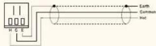
8 What is the proper wiring for the screw terminal type input modules?
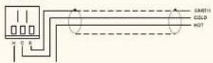
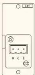
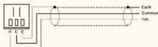
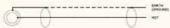
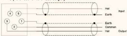
Pin 1: Earth. Pin 2: Common. Pin 3: Hot. When wiring an unbalanced source to a balanced input module: Connect the source (+) output to Pin 3 Hot. Connect the source (-) or shield output to Pin 2 Common.
9 What's the difference between the "L" Series and "B" Series modules?
“B” Series modules are balanced, line level, high impedance inputs.
“L” Series modules are balanced, line level, low impedance inputs.
Most modern audio equipment provide low impedance outputs which are designed to drive high impedance inputs. Maximum voltage transfer occurs when the input impedance is at least ten times the source output impedance. Almost all of the output signal voltage is transferred to the input.
Impedance matching (output impedance to input impedance) results in maximum power transfer and causes approximately -6dB of signal voltage loss. This can often exceed a source device's minimum output load impedance specification. In most cases, use B Series instead of L Series modules.
10 Which modules are for "mute send"?
M-41S for microphone level input. B-41S, L-41S for balanced line level input. U-43R, U-43S for unbalanced line level input. ML-11T for microphone or line level input (selectable). S-20S is a digital message repeater module with mute send select-ability.
11 Which modules are for "mute receive"?
M-11S for microphone level input. B-11S for balanced line level input. L-11 for balanced or unbalanced line level input, low impedance, line matching. ML-11T for microphone or line level input (selectable). U-11R, U-11S, U-12S & U-13R can be used for unbalanced line level input. U-14R for unbalanced dual input priority (Jukebox input mutes BGM input), both are muted when the mute receive jumper is set.
Troubleshooting
12 Why won't the M-11 (Microphone Input with Mute-Receive) pass signal?
The M-11 will not pass signal "out-of-the-box". Cut jumpers to select the mute response mode: Normally-Off or Normally-On. See page 35, Jumper Settings, for more information.
13 Why won't my paging source override my music source?
First, verify that the paging source is connected to a Mute-Send module and the music source is connected to a Mute-Receive module. Next, verify that the module jumpers are configured for Mute Bus #1 or Mute Bus #2 (or both). Test the Mute-Receive module's mute function by placing a jumper between Mute Bus #1 (or #2) and Ground terminals. Last, adjust the Mute-Send module's "Sensitivity" control to lower the mute activation threshold. The Mute-Send module activates the mute function based on input signal level exceeding this threshold.
14 Why isn't my condenser microphone working with an M Series module?
Verify that Jumper "J1" on the M Series module circuit board is intact and secure the module to the chassis with the supplied screws.
15 Why is my signal level low with an L Series module?
Removing resistor R1 (680 Ω) on the module's circuit board will provide approximately 6 dB additional gain by converting the module's input impedance to 10 kΩ. See page 16, "Impedance Matching".
MODULAR PRODUCTS REFERENCE
| Model A-706 | A-901A | A-903A | A-903MK2 | BG-1015 M-900A | M-900MK2 | P-906A | P-906MK2 | W-906A | ||||
| A-712 | A-906A | A-906MK2 | BG-1030 P-912A | P-912MK2 | W-912A | |||||||
| A-724 | A-912A | A-912MK2 | BG-1060 | BG-1120 | P-924A | P-924MK2 | ||||||
| Mixer/Amplifier | Mixer/Amplifier | Mixer/Amplifier | Mixer/Amplifier | Mixer/Amplifier | Mixer/Pre-amplifier | Mixer/Pre-amplifier | PowerAmplifier | PowerAmplifier | Wall-mountMixer/Amplifier | |||
| Discontinued | Discontinued | Discontinued | Discontinued | Screw terminalor RTBmodulesonly | ||||||||
| Power | 60 / 120 /240 W | 10 W | 30 / 60 /120 W | 30 / 60 /120 W | 15 / 30 /60 / 120 W | N/A | N/A | 60 / 120 /240 W | 60 / 120 /240 W | 60 / 120 W | ||
| Module Slots | 1 | 2 | 6 | 8 | 1 | 6 | 8 | 1 | 1 | 6 (exp. to 8) | ||
| Mute Bus(es) | 1 | 1 | 1 | 2 | N/A | 1 | 2 | 0 | 0 | 1 | ||
| Pre-Out /Power-InJacks | Y | N | Y | Y | Y | N | N | N | N | N | ||
| MODULE | ||||||||||||
| ML-11T | Y | Y | Y | Y | Y | Y | Y | Y | Y | Y | ||
| M-01 | Y | Y | Y | Y | Y | Y | Y | Y | Y | Y | ||
| M-11 | N | Ch. #2 only | Y | Y | N | Y | Y | N | N | Y | ||
| M-21 | Y | Y | Y | Y | Y | Y | Y | Y | Y | Y | ||
| M-41 | N | Ch. #2 only | Y | Y | N | Y | Y | N | N | Y | ||
| M-51 | Y | Y | Y | Y | Y | Y | Y | Y | Y | Y | ||
| M-61 | Y | Y | Y | Y | Y | Y | Y | Y | Y | Y | ||
| M-03 | Y | Y | Y | Y | Y | Y | Y | Y | Y | N | ||
| B-01 | Y | Y | Y | Y | Y | Y | Y | Y | Y | Y | ||
| B-11 | N | Ch. #2 only | Y | Y | N | Y | Y | N | N | Y | ||
| B-21 | Y | Y | Y | Y | Y | Y | Y | Y | Y | Y | ||
| B-41 | N | Ch. #2 only | Y | Y | N | Y | Y | N | N | Y | ||
| L-01 | Y | Y | Y | Y | Y | Y | Y | Y | Y | Y | ||
| L-11 | N | Ch. #2 only | Y | Y | N | Y | Y | N | N | Y | ||
| L-41 | N | Ch. #2 only | Y | Y | N | Y | Y | N | N | Y | ||
| U-01 | Y | Y | Y | Y | Y | Y | Y | Y | Y | Y | ||
| U-03 | Y | Y | Y | Y | Y | Y | Y | Y | Y | Y | ||
| U-11 | N | Ch. #2 only | Y | Y | N | Y | Y | N | N | Y | ||
| U-12 | N | Ch. #2 only | Y | Y | N | Y | Y | N | N | Y | ||
| U-13 | N | Ch. #2 only | Y | Y | N | Y | Y | N | N | Y | ||
| U-14R | Y | Y | Y | Y | Y | Y | Y | Y | Y | Y | ||
| U-21 | Y | Y | Y | Y | Y | Y | Y | Y | Y | Y | ||
| U-43 | N | Ch. #2 only | Y | Y | N | Y | Y | N | N | Y | ||
| U-61 | Y | Y | Y | Y | Y | Y | Y | Y | Y | Y | ||
| T-01 | Y | N | Ch. #5 and#6 only | Y | Y | Ch. #5 and#6 only | Y | N | N | Ch. #5 and#6 only | ||
| T-02 | Y | Y | Y | Y | Y | Y | Y | Y | Y | Y | ||
| T-12 | N | Ch. #2 only | Y | Y | N | Y | Y | Y | Y | Y | ||
| S-01 | Y | Y | Y | Y | Y | Y | Y | Y | Y | Y | ||
| S-02 | Y | Y | Y | Y | Y | Y | Y | Y | Y | Y | ||
| S-04 | Y | Y | Y | Y | Y | Y | Y | Y | Y | Y | ||
| S-20S | Y | Y | Y | Y | Y | Y | Y | Y | Y | Y | ||
| V-01S | Y | Y | Y | Y | Y | Y | Y | Y | Y | Y | ||
| E-03/04 | Y | N | Y | Y | Y | Y | Y | Y | Y | N | ||
| E-05/06 | Y | N | Y | Y | Y | Y | Y | Y | Y | N | ||
| E-07 | Y | N | Ch. #5 and#6 only | Y | Y | Ch. #5 and#6 only | Y | N | N | Ch. #5 and#6 only |
DISCONTINUED MODULE CROSS-REFERENCE
| Discontinued Description Current Model | ||
| H-01 Microphone Input, Low Impedance M-01 Series, ML-11T | ||
| H-02 Microphone Input, Low Impedance (Low cut only) M-01 Series, ML-11T | ||
| H-21 Microphone Input, Low Impedance, with Remote Volume Control M-21S | ||
| H-22 | Microphone Input, Low Impedance, with Remote Volume Control (Low cut only) | M-21S |
| H-31 Microphone Input, Low Impedance, with Mute Receive M-11S, ML-11T | ||
| H-32 Microphone Input, Low Impedance, with Mute-Receive (Low cut only) M-11S, ML-11T | ||
| H-03 Microphone Input, High Impedance M-03P | ||
| S-03S Chime S-04S | ||
| X-01 Unbalanced Line Input U-01, U-03 Series | ||
| X-11 Unbalanced Line Input with Mute-Receive | U-11, U-13 Series | |
| X-21 | Unbalanced Line Input with Remote Volume Control | U-21S |
Notes:
- H Series microphone modules do not provide phantom power.
- Original mute-type modules (pre-1994) connect to Mute Bus #1 only. Newer "MK2" mute-type modules connect to both Mute Bus #1 and Mute Bus #2 and have a "MK2" label on the module faceplate.
JUMPER SETTINGS
| Function Model Jumper Jumper Details | ||||
| Mute-Receive M-11, T-12, U-11, J5 J6U-12, U-13, U-14R ON ON | ||||
| ON Responds to both Mute Bus #1 and Mute Bus #2 activation. | ||||
| CUT ON Responds to Mute Bus #1 activation only | ||||
| ON CUT Responds to Mute Bus #2 activation only | ||||
| CUT CUT No mute function | ||||
| B-11, L-11 D3 | D4 | |||
| ON ON Responds to both Mute bus #1 and Mute bus #2 activation. | ||||
| CUT ON Responds to Mute Bus #1 activation only | ||||
| ON CUT Responds to Mute Bus #2 activation only | ||||
| CUT CUT No muting | ||||
| M-11S Mute Response Mode | M-11 | J3 J4 | (Normally-On or Normally-Off) | |
| ON ON No output signal - cut J3 or J4. | ||||
| CUT ON Normally "OFF" turns "ON" during mute bus activation | ||||
| ON CUT Normally "ON" turns "OFF" during mute bus activation | ||||
| CUT CUT No muting function. | ||||
| Mute-Send | S-20S | SJP2 | Enables Mute Send (VOX) | |
| M-41, U-43 | J5 J6 | |||
| ON ON Activates both Mute Bus #1 and Mute Bus #2 | ||||
| CUT ON Activates only Mute Bus #1 | ||||
| ON CUT Activates only Mute Bus #2 | ||||
| CUT CUT No mute activation. | ||||
| B-41, L-41 D3 | D4 | |||
| ON ON Activates both Mute Bus #1 and Mute Bus #2 | ||||
| CUT ON Activates only Mute Bus #1 | ||||
| ON CUT Activates only Mute Bus #2 | ||||
| CUT CUT No mute activation. | ||||
| Phantom Power | M-01, M-11, M-21,M-41, M-51, M-61 | J1 | ||
| CUT | Disables phantom power. | |||
| Master Compressor | U-61 | J2 | ||
| CUT | Configures module as a Master Compressor(see page 23). | |||
| Remote Master Volume | U-21 | CUT | Configures module as a Remote Master Volume control(see page 21). | |
| Input Impedance Conversion(600 Ω to 10 kΩ) | L-01, L-11, L-41 | R1 | ||
| CUT | Changes input impedance from 600 Ω to 10 kΩallowing maximum voltage transfer (see page 16). | |||
| Hysteresis | ML-11T | SJP101 | Disables Mute Send hysteresis | |
| CUT | ||||
| Mute Send (VOX) | SJP102 | Enables VOX function | ||
| ON | Disables VOX function | |||
| OFF | ||||
| Mute Bus #1 | SJP103 | Responds to Mute Bus #1 activation only | ||
| Receive | Activates only Mute Bus #1 | |||
| Send | ||||
| N/A Disconnects from Mute Bus #1 | ||||
| Mute Bus #2 | SJP104 | Responds to Mute Bus #2 activation only | ||
| Receive | Activates only Mute Bus #2 | |||
| Send | ||||
| N/A Disconnects from Mute Bus #2 | ||||
Note:
1. In many applications, NO jumper changes are required. Mute-Receive and Mute-Send modules connect to both Mute Bus #1 and Mute Bus #2 by default.
2. Configure the M-11S Mute Response Mode before use - it will not pass signal out-of-the-box.
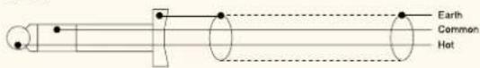
CONNECTOR WIRING
| Model Connector Type Pinout | ||||
| B-01F XLR jack, Female Pin 1: Earth (shield) Pin 2: Common Pin 3: Hot | ||||
| B-01S Removable terminal block Pin 1: Earth (shield) Pin 2: Common Pin 3: Hot | ||||
| B-11S Removable terminal block Pin 1: Earth (shield) Pin 2: Common Pin 3: Hot | ||||
| B-21S Screw terminals, 5 pin Pin 1: Earth (shield) Pin 2: Common Pin 3: Hot | ||||
| Pin 4 and 5: Remote Volume Control - 10 kΩ (linear-taper potentiometer) | ||||
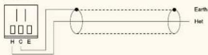
| B-41S Removable terminal block H: Hot C: Common E: Earth (shield) | ||||
| E-03R RCA jack, dual Tip: Hot Sleeve: Earth (shield) | ||||
| E-04R RCA jack, dual Tip: Hot Sleeve: Earth (shield) | ||||
| E-05R RCA jack, dual Tip: Hot Sleeve: Earth (shield) | ||||
| E-06R RCA jack, dual Tip: Hot Sleeve: Earth (shield) | ||||
| E-07S | Removable terminal block | Pin 1: Earth (shield) | Pin 2: Common | Pin 3: Hot (output) |
| L-01F XLR jack, Female Pin 1: Earth (shield) Pin 2: Common Pin 3: Hot | ||||
| L-01S | Removable terminal block | Pin 1: Earth (shield) | Pin 2: Common | Pin 3: Hot |
| L-11S | Removable terminal block | Pin 1: Earth (shield) | Pin 2: Common | Pin 3: Hot |
| L-41S | Removable terminal block | Pin 1: Earth (shield) | Pin 2: Common | Pin 3: Hot |
| M-01F | XLR jack, Female | Pin 1: Earth (shield) | Pin 2: Common | Pin 3: Hot |
| M-01M | XLR jack, Male | Pin 1: Earth (shield) | Pin 2: Common | Pin 3: Hot |
| M-01P | 1/4" phone jack | Tip: Hot | Ring: Common | Sleeve: Earth (shield) |
| M-01S | Removable terminal block | Pin 1: Earth (shield) | Pin 2: Common | Pin 3: Hot |
| M-03P | 1/4" phone jack | Tip: Hot | Ring: Common | Sleeve: Shield |
| M-11S | Removable terminal block | Pin 1: Earth (shield) | Pin 2: Common | Pin 3: Hot |
| M-21S | Screw terminals, 5 pin | Pin 1: Earth (shield) | Pin 2: Common | Pin 3: Hot |
| Pin 4 and 5: Remote Volume Control - 10 kΩ (linear-taper potentiometer) | ||||
| M-41S | Removable terminal block H: Hot C: Common E: Earth (shield) | |||
| M-51F | XLR jack, Female | Pin 1: Earth (shield) | Pin 2: Common | Pin 3: Hot |
| M-51S | Removable terminal block | Pin 1: Earth (shield) | Pin 2: Common | Pin 3: Hot |
| M-61F | XLR jack, Female | Pin 1: Earth (shield) | Pin 2: Common | Pin 3: Hot |
| M-61S | Removable terminal block | Pin 1: Earth (shield) | Pin 2: Common | Pin 3: Hot |
| ML-11T | Removable terminal block | Hot | Cold | Earth |
| S-01S | Removable terminal block | Pin 1: Earth | Pin 2: 1 kHz Tone | Pin 3: n/a |
| S-02S | Removable terminal block | Pin 1: Earth | Pin 2: Buzzer | Pin 3: Yelp |
| S-04S | Removable terminal block | Pin 1: Earth | Pin 2: Continuous Tone | Pin 3: Single Tone |
| S-20S | Removable terminal block | Message 1 - 4 | Stop | Common |
| T-01S | Removable terminal block | Pin 1: Earth (shield) | Pin 2: Common | Pin 3: Hot (output) |
| T-02S | Screw terminals, 5 pin | Pin 1: Earth (shield) | Pin 2: Common (output) | Pin 3: Hot (output) |
| Pin 4: Hot (input) | Pin 5: Earth (shield) | |||
| T-12S | Screw terminals, 5 pin | Pin 1: Earth (shield) | Pin 2: Common (output) | Pin 3: Hot (output) |
| Pin 4: Hot (input) | Pin 5: Earth (shield) | |||
| U-01F | XLR jack, Female | Pin 1: Earth (shield) | Pin 2: Earth (shield) | Pin 3: Hot |
| U-01P | 1/4" phone jack | Tip: Hot | Sleeve: Earth (shield) | |
| U-01R | RCA jack, single | Tip: Hot | Sleeve: Earth (shield) | |
| U-01S | Removable terminal block | Pin 1: Earth (shield) | Pin 2: Earth (shield) | Pin 3: Hot |
| U-03R | RCA jack, dual (stereo summing) | Tip: Hot | Sleeve: Earth (shield) | |
| U-03S | Removable terminal block | H: Hot | C: Common | E: Earth (shield) |
| U-11R | RCA jack, single | Tip: Hot | Sleeve: Earth (shield) | |
| U-11S | Removable terminal block | Pin 1: Earth (shield) | Pin 2: Earth (shield) | Pin 3: Hot |
| U-12S | Removable terminal block | Pin 1: Earth (shield) | Pin 2: Earth (shield) | Pin 3: Hot |
| U-13R | RCA jack, dual (stereo summing) | Tip: Hot | Sleeve: Earth (shield) | |
| U-13S | Removable terminal block | H: Hot | C: Earth (shield) | E: Earth (shield) |
| U-14R | RCA jack, dual (stereo summing) | Tip: Hot | Sleeve: Earth (shield) | |
| U-21S | Screw terminals, 5 pin | Pin 1: Output (cut J2) | Pin 2: Earth (shield) | Pin 3: Hot |
| Pin 4 and 5: Remote Volume Control - 10 kΩ (linear-taper potentiometer) | ||||
| U-43R | RCA jack, dual (stereo summing) | Tip: Hot | Sleeve: Earth (shield) | |
| U-43S | Removable terminal block | H: Hot | C: Earth (shield) | E: Earth (shield) |
| U-61S | Removable terminal block | Pin 1: Output (cut J2) | Pin 2: Earth (shield) | Pin 3: Hot |
| V-01S | Removable terminal block | Tip: Hot | Sleeve: Earth (shield) | +/-24 VDC CTRL |
TOA ELECTRONICS, INC.
TEL: 800-733-7088
FAX: 800-733-9766
TOA CANADA
CORPORATION
TEL: 905-564-3570
FAX: 905-564-3569


- Series Module Guide
- TABLE OF CONTENTS
- INTRODUCTION....1
- MODULE SELECTION ....3
- MODULE SELECTION CHART 5
- MUTING 7
- MICROPHONE INPUT MODULES 9
- LINE INPUT MODULES 13
- SPECIAL FUNCTION MODULES 24
- APPLICATIONS....30
- FREQUENTLY ASKED QUESTIONS ....31
- General
- Troubleshooting
- MODULAR PRODUCTS REFERENCE CHART....33
- MODULE CROSS-REFERENCE CHART 34
- JUMPER SETTINGS CHART 35
- CONNECTOR WIRING CHART....36
- Welcome to the TOA 900 Series Module Guide!
- Module Categories
- Model Numbers
- Signal Levels
- Microphone (Mic) Level
- 2.Line Level
- 3.Speaker Level
- Notes:
- Installation Notes
- MODULE SELECTION CHART
- Muting Defined
- Mute Buses
- Mute Function Activation
- Mute-Send
- Switch Activation
- MICROPHONE INPUT MODULES
- Microphone/Line Input with Mute Send/Receive
- SPECIFICATIONS
- M-01 Series Microphone Input
- M-11S Microphone Input with Mute-Receive
- M-21S Microphone Input with Remote Volume Control
- M-41S Microphone Input with Mute-Send
- M-51 Series Microphone Input with Voice Gate
- M-61 Series Microphone Input with Compressor
- M-03P High Impedance Microphone Input
- LINE INPUT MODULES
- ML-11T Microphone/Line Input with Mute Send/Receive
- B-01 Series Balanced Line Input
- CONNECTOR DIAGRAMS
- B-11S Balanced Line Input with Mute-Receive
- CONNECTOR DIAGRAM
- B-21S
- Balanced Line Input with Remote Volume Control
- B-41S Balanced Line Input with Mute-Send
- IMPEDANCE MATCHING
- L-01 Series Line Matching Input
- Line Matching Input with Mute-Receive
- L-41S Line Matching Input with Mute-Send
- UNBALANCED LINE INPUT
- U-01 Series Unbalanced Line Input
- U-03 Series Unbalanced Line Input with High/Low Cut Filters
- U-11 Series Unbalanced Line Input with Mute-Receive
- U-12S Unbalanced Line Input with Variable Mute-Receive Depth
- U-13 Series Unbalanced Line Input with High/Low Cut Filters and Mute-Receive
- U-14R Dual Input Priority w/AGC and Mute-Receive
- U-21S Unbalanced Line Input with Remote Volume Control
- U-43 SERIES Unbalanced Line Input with High/Low Cut Filters and Mute-Send
- U-61S Unbalanced Line Input with Compressor
- SPECIAL FUNCTION MODULES
- T-01S Balanced Line Output
- T-02S Unbalanced Line Input with Music-On-Hold Output
- T-12S Unbalanced Line Input with Music-On-Hold Output & Input Mute-Receive
- SPECIAL FUNCTION MODULES: TONE GENERATOR
- S-20S Digital Message/Tone w/USB and Mute-Send
- S-01S 1 kHz Sine Wave Test Tone
- S-02S Buzzer/Yelp Tone
- S-04S Switch-Selectable Tone
- SPECIAL FUNCTION MODULES: VOLUME CONTROL
- V-01S Remote Master Volume Control (VCA)
- E Series Processor Modules for TOA Speakers
- Connection Methods:
- A-903MK2, A-906MK2, A-912MK2 Mixer/Amplifiers
- M-900MK2 Mixer/Pre-amplifier
- P-906MK2, P-912MK2, P-924MK2 Power Amplifiers
- SPECIFICATIONS (E-03R - E-06R)
- APPLICATIONS
- Paging Over a Music Source
- Telephone Paging and Music-On-Hold
- Banquet Room Sound System
- School Gymnasium Sound System
- FREQUENTLY ASKED QUESTIONS
Brand : TOA
Model : U-01S
Category : Audio Modules