
KEX315 - Heating Kaden - Free user manual and instructions
Find the device manual for free KEX315 Kaden in PDF.

| Product Type | Gas-Fired Ducted Central Heater (External) |
| Model | KEX315 |
| Brand | Kaden |
| Gas Type | Natural Gas Only |
| Maximum Input | 66 MJ/hr |
| Maximum Heat Output | 15.5 kW |
| Power Supply | 220-240 V, 50 Hz, 10 A (3-pin plug) |
| Power Consumption (Fan Motor) | 250 W |
| Total Maximum Current | 4 A |
| Overall Dimensions (H x W x D) | 1145 x 850 x 420 mm |
| Net Weight | 57 kg |
| Duct Connection Size (Supply/Return) | 300 mm diameter (each) |
| Minimum Return Air Grille Area (no filter) | 0.19 m² |
| Minimum Return Air Grille Area (with filter) | 0.28 m² |
| Airflow at 125 Pa Static Pressure | 443 L/s |
| Fan Speed Options | High, Medium, Low (factory default High) |
| Safety Features | Overheat switch, flame rollout protection, pressure switch, lockout with error codes |
| Installation Type | External (wall-mounted), ground level |
| Warranty | Refer to manufacturer's warranty card (online registration required) |
| Compliance | AS/NZS 5601, AS/NZS 3000, AS/NZS 5141, local regulations |
| Add-On Cooling Compatible | Not recommended (maximum capacity N/A) |
| Wall Control Supplied | Kaden Manual Wall Control (wired) |
Frequently Asked Questions - KEX315 Kaden
User questions about KEX315 Kaden
0 question about this device. Answer the ones you know or ask your own.
Ask a new question about this device
Download the instructions for your Heating in PDF format for free! Find your manual KEX315 - Kaden and take your electronic device back in hand. On this page are published all the documents necessary for the use of your device. KEX315 by Kaden.
USER MANUAL KEX315 Kaden
Safety Information Installation Commissioning
Models
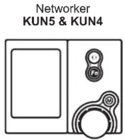
Universal:
KUN3 | KUN4 | KUN5
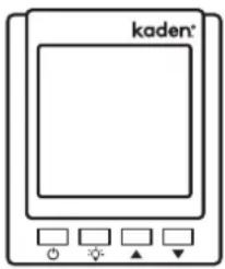
External
KEX3 | KEX4
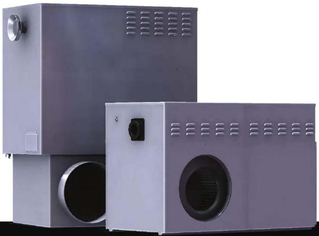
natural_image
Three industrial air purifiers with ventilation grilles, shown from different angles (no text or symbols visible)Table of Contents
Warnings and Important Information 4
Scope 6
1. General Guidelines 7
1.1 Inspection....7
1.2 Unpacking the Heater 7
1.3 Unloading or Lifting the Heater 7
1.4 Gas Inlet Connection 8
1.5 Electrical Power Supply 8
1.6 Installation of Duct Connection Pops 8
1.7 Heater Positioning....9
1.8 Installation of Internal Heaters 9
1.8.1 Installing in the Roof Space 9
1.8.2 Installing Beneath the Floor 9
1.9 Installation of Internal Heaters - Room, Enclosure or Plant Room....10
1.10 External Installations....10
2. KUN Universal Model Guidelines 11
2.1 Heater Dimensions....11
2.2 Platform & Service Clearances....11
2.3 Internal Installation 12
2.3.1 Splitting the Heater 12
2.3.2 POP Configuration Installation....12
2.3.3 Return & Supply Air POP Rotation Procedure 13
2.3.4 Internal Model Flueing Instructions....14
2.3.5 Kaden Remote Flue Terminal....14
2.4 External Installation....15
2.4.1 Supply Air Overheat Switch Position (KUN530 & KUN330 ONLY) 15
2.4.2 Modifying KUN Model Duct Orientation....15
2.4.3 Installation of Flue Terminal....16
2.4.4 Area to Cut Out in Wall....16
2.4.5 Installation of Flashing 17
2.4.6 KUN3 & KUN4 models....17
2.4.7 Thermistor Installation KUN4 & KUN5....18
3. KUN4 & KUN5 19
3.1 Wiring a Damper Motor to the Heater's Control Module 19
3.1.1 Damper Motor Connections....20
3.1.2 RJ Socket Connections 20
3.1.3 RJ12 socket detail on heater PCB 20
4. KEX External Model Guidelines 21
4.1 Heater Dimensions....21
4.2 Service Clearances....21
4.3 Installation 22
4.3.1 Area to Cut Out in Wall 22
4.3.2 Installation of Flashing 22
4.3.3 Installation of Flue Terminal 23
4.3.4 Flue Terminal Clearances....23
5. Fan Speed KUN3, KEX3 & KEX4 24
5.1 Fan Speed Setting For KUN3, KEX3 & KEX4 Models 24
5.1.1 To Adjust The Fan Speed....24
6. Ducting Information 25
6.1 Minimum Recommended Return Air Grille Selection Chart 25
7. Outlet Guide 26
7.1 Outlet Register Chart 27
8. Wall Control Installation 28
8.1 Networker Installation KUN4 & KUN5....29
8.1.1 Wiring the Networker to a KUN4 & KUN5 Heater 29
8.2 Manual Wall Control Installation 30
8.2.1 Wiring the Manual Wall Control to a KUN3 Heater 30
8.2.2 Wiring the Manual Wall Control to a KEX4 & KEX3 Heaters 30
9. Commissioning KUN4 & KUN5 32
9.1 Heater Control Settings....32
9.2 Installer Parameters Via Networker 33
9.2.1 Networker Installer Parameter KUN4 & KUN5 33
9.2.2 Adjust Networker Parameters....34
9.3 KUN4 & KUN5 Commissioning Instructions 34
9.3.1 Initial Ignition and Gas Inlet Pressure Check 34
9.3.2 Heater Fan Speed and Temperature Settings.... 35
9.3.3 Final Checks 36
9.4 Fault Code Identification on Heater PCB 36
9.4.1 NG-3 L.E.D Identification 36
9.4.2 Error codes associated with installation 37
10. Commissioning KUN3, KEX3 & KEX4 38
10.1 Commissioning Instructions 38
10.1.1 Start & Check Supply Pressure 38
10.1.2 Start & Check Burner Pressure 38
10.1.3 Setting the Fan Speed 39
10.1.4 Final Checks 39
11. Technical Specifications 40
12. Technical Support 41
WARNINGS AND IMPORTANT INFORMATION

READ ALL INSTRUCTIONS BEFORE USING THE APPLIANCE.
Failure to carefully read and follow all instructions in this manual can result in equipment malfunction, property damage, personal injury and/or death.
WARNINGS: WHEN IGNORED, CAN RESULT IN SERIOUS INJURY OR DEATH.
CAUTIONS: WHEN IGNORED, CAN RESULT IN MINOR INJURY OR PRODUCT DAMAGE.
SHALL / MUST/ IMPORTANT:
INDICATES A MANDATORY REQUIREMENT OF THIS MANUAL.
SHOULD:
INDICATES A RECOMMENDED REQUIREMENT OF THIS MANUAL.
Any deviations from these instructions may void the warranty. As a result, the customer and/or installer may be charged a fee for product non-warranty related call outs. Also, note that failure to comply with these instructions may preclude servicing of the unit.
DISCLAIMER:
This document is a guide only. Laws, regulations and industry standards can vary between States and Territories. Accordingly, this guide MUST BE read in conjunction with, and subject to, all laws, regulations and industry standards applicable in the State or Territory in which the products are installed. You MUST ensure that the installation of the products will comply with those laws, regulations and standards, and that the products recommended to customers are fit for the purpose for which they are intended.

REGULATORY / INSTALLATION / SAFETY
This appliance SHALL BE installed in accordance with:
Manufacturer's Installation Instructions and the Kaden Sizing Guide.
Current AS/NZS 5601 (Gas Installation Standard), AS/NZS 5141 (Residential Climate Control Systems), AS/NZS 3000 (Electrical Codes) and Local Gas / Electrical authority regulations.
Current AS 4254 Ductwork for air-handling systems in buildings, EPA guidelines and HB276-2004 "A Guide to Good Practice"
Local Regulations and Municipal Building Codes (BCA) including local OH&S requirements.
ALWAYS comply with the following precautions to avoid dangerous situations and to ensure optimum performance.
This appliance MUST BE installed, maintained and removed by an Authorised Person.
DO NOT place any articles on or against this appliance
DO NOT use or store flammable materials near this appliance
DO NOT spray aerosols in the vicinity of this appliance while it is in operation
DO NOT modify this appliance
This appliance is NOT intended for use by persons (including children) with reduced physical, sensory or mental capabilities, or lack of experience and knowledge, unless they have been given supervision or instruction concerning use of the appliance by a person responsible for their safety
Children should be supervised to ensure that they DO NOT play with the appliance.

The Kaden Networker controller is used as a Wired Wall Thermostat and is also the interface to set Installer Parameters and obtain diagnostic information on the Kaden KU4 and KU5 Ducted Gas Heaters. A spare Networker should be kept on hand for such purposes.

The manufacturer cannot guarantee compatibility and support for anyone using 3rd party accessory/devices (device) on any of their appliances.
The suitability, compatibility or functional performance of any 3rd party device is entirely the responsibility of the device's supplier or installer.
Any 3rd party device, technical, installation, operation, performance or other enquiries need to be referred to the device's supplier or installer.
Any adverse effects of 3rd party devices on the operation, performance or reliability of this appliance is not covered by the manufacturer's product warranty.
SCOPE
This Installer's Manual is intended to be used as a guideline for the installation of Kaden Gas Fired Central Heaters. It covers only the installation and commissioning of the heater and the allowable flueing configurations.
Although recommended return air grilles and allowable duct outlet quantities are specified, it does not cover the actual ducting design required to suit the installation.
This Installer's Manual is based on Australian codes – for all other applications, please refer to local codes and regulations.
Kaden heaters must be installed and serviced by qualified personnel.
Models covered in this manual are as follows:
| Kaden Universal Heaters Type of Wall Control (Thermostat) Supplied | ||
| KUN5 Series | KUN521 | Kaden Networker |
| KUN530 | ||
| KUN4 Series | KUN415 | Kaden Networker |
| KUN420 | ||
| KUN425 | ||
| KUN430 | ||
| KUN3 Series | KUN315 | Kaden Manual |
| KUN320 | ||
| KUN325 | ||
| KUN330 | ||
| Kaden External Heaters Type of Wall Control (Thermostat) Supplied | ||
| KEX4 Series | KEX415 | Kaden ManualKEX420 |
| KEX428 | ||
| KEX3 Series | KEX315 | Kaden ManualKEX320 |
| KEX328 | ||
Manual
KUN3, KEX3 & KEX4

All Kaden models are Natural Gas ONLY.
All Kaden models are non-condensing.
Universal models may be used in both internal & external applications.
For more details refer to "11. Technical Specifications" on page 41
1. GENERAL GUIDELINES
Kaden heaters are designed to provide a central source of heat for a ducted central heating system.
Kaden heaters should not be installed downstream from an air washer, an evaporative cooler or refrigerative cooling system. Nor are they designed to be installed on a marine craft, houseboat, or any similar environment.
Kaden heaters must be installed in accordance with these instructions and related regulations, codes, standards, and authorities. These include but may not be limited to:
- Kaden Sizing Guide
• AS/NZS 3000 – Electrical Installations
• AS/NZS 5601 – Gas Installations
• AS/NZS 5141 – Residential Climate Control Systems - AS 4254 – Ductwork for Air-Handling Systems in Buildings
- Local Building Regulations
• HB 276 – A Guide to Good Practice
• Environment Authorities - Local Gas and Electricity Authority Codes
• Building Code of Australia (BCA)

The installer assumes the responsibility for equipment installed in violation of any code, regulations and these installation instructions.
It is recommended the Kaden Sizing Guide be followed in estimating heating requirements and for system design that will result in efficient installation and provide a higher level of comfort and economical operation.
For the hourly input and the gas type to be used, see the appliance data label located inside the service compartment or "11. Technical Specifications" on page 40.
1.1 INSPECTION
This appliance has been inspected and tested at the time of manufacture, packaged and released for transportation without known damage. Upon receipt, inspect the exterior for evidence of rough handling in shipment.
Ensure that the appliance is labelled correctly for the gas to which it is intended to be connected. Immediately report to supplier any discrepancies or damage.

This appliance can only be connected to Natural Gas.
1.2 UNPACKING THE HEATER
Heaters are supplied with a box cover. To unpack:
- Cut and remove any nylon straps.
- Lift the box off and dispose of thoughtfully.
- Remove the packaging and dispose of thoughtfully.

Always remove and dispose of the plastic film before mounting the heater onto a base box (if fitted).
1.3 UNLOADING OR LIFTING THE HEATER
When unloading or lifting the heater, ensure lifting equipment is in good operating condition and capable of lifting the total load.
Ensure there is a clear area to place the heater down, which is within reach of the lifting equipment.

If fitting the heater to elevated heights such as a roof, use suitable lifting equipment.
1.4 GAS INLET CONNECTION
- All piping must be in accordance with AS/NZS 5601 and any local gas regulations.
- The connection point for all Kaden model heaters is a female G3/4 compression fitting to AS 3688. For KEX models this is located at the base of the heaters outer cabinet, and for KUN models the gas feed tube is supplied loose in the control compartment and MUST BE fitted to suit the installation.
- A gas cock shall be fitted in the gas line adjacent to the heater and in a convenient location so it can be turned OFF quickly and easily.
- The gas supply shall in no way interfere with any servicing of the heater.

The gas supply must be installed by a licensed gas fitter. The gas pipe and gas meter should be sized so the heater can maintain its required incoming gas pressure at maximum consumption with all other gas appliances operating at their maximum capacity at the same time as the heater.
1.5 ELECTRICAL POWER SUPPLY
The heater is pre-wired with a 3-pin plug and lead, and shall be plugged into a standard 10 Amp 220 to 240 volt fixed switched socket outlet adjacent to the heater, in a convenient location so it can be turned OFF quickly and easily.

A qualified electrician must install the 220 to 240 volt wiring according to local regulations.

Switch OFF the power and unplug the heater before touching any wiring. If any electrical wiring is damaged, it must be replaced by the manufacturer, its service agents or an electrically qualified technician, in order to avoid a hazard.
The electricity supply must be 220 to 240 V at 50 Hz, and from an authorised power supplier. Generators should never be used, as their output may be incompatible with, or prone to damage the heater's electronic components.
1.6 INSTALLATION OF DUCT CONNECTION POPS
On Kaden KUN Series heaters, the pops need to be fastened to the heater cabinet as follows:
- Insert pops into the hole in the POP plate, ensuring the POP flange is placed over the prescribed wall of the cabinet, refer to the "POP Installation Matrix" below.
- Spread POP flange to fit tightly into the hole in the cabinet (the notch side overlapping the other).
- Secure pops with the rivets supplied.
| POP Installation Matrix | ||||
| Series | Return Air Supply Air | |||
| Number of walls Installation POP Number of walls Installation POP | ||||
| KUN3 1 No Option 2 Inner Wall | ||||
| KUN4 2 Inner Wall 2 Inner Wall | ||||
| KUN5 2 Inner Wall 2 Inner Wall | ||||
Table 1

The POP is fitted to a POP plate for some models and a panel for others.
1.7 HEATER POSITIONING
Install the heater in a position that allows adequate and safe access for service as per guidelines in this manual and a applicable standards. The cost of any equipment and additional labour involved in accessing such heater installations will not be accepted for warranty purposes.

All service clearance measurements must be adhered to, otherwise this will impede the serviceability of the heater.
1.8 INSTALLATION OF INTERNAL HEATERS
All Kaden Universal models are primarily designed to be installed in the roof or beneath the floor. This must be done in accordance with the following guidelines and AS/NZS 5601.
1.8.1 Installing in the Roof Space
- The area under the heater shall be capable of supporting the additional load, without causing deformation of any part of the building structure.
- The appliance shall be accessible by means of fixed access, a normal ladder or steps.
- A passage of 600mm wide shall be provided between the roof access opening and the heater.
- This passage shall have a suitable walkway of at least 19mm thick particle board or equivalent.
- A permanent level platform shall be provided beneath the heater and this platform area shall extend 750mm out from the controls access panel side and fan motor access panel side/s for the entire length of the heater.
- The air gap created between the base of the heater and the platform by the heater's legs shall be maintained.
- Permanent artificial lighting shall be provided at the heater, with the switch located at the roof access opening.
1.8.2 Installing Beneath the Floor
- There shall be a minimum clearance of 200mm between any part of the appliance and the lowest part of the floor structure. In addition to this, refer to “Service Clearances” for the specific Kaden KUN model.
- The heater shall be located within 2m of the access opening, or there is to be a minimum clearance of 1.2m between the lowest part of the floor structure and ground level, maintained from the access opening to the heater.
- All under floor installations shall be on a level concrete base (50mm thick), and provision made to drain any condensate, seepage or ground water away from the heater.
- Permanent artificial lighting shall be provided at the heater with the switch located at the access opening.
- Lateral (horizontal) flues may be installed in accordance with AS/NZS 5601, ensuring that the lateral flue section has a minimum rise of a 20mm per metre of lateral run.
- The flue shall be terminated outside the building in accordance with AS/NZS 5601. For KUN heaters, termination can be performed using a Remote Flue Terminal. Refer to Internal Model Flueing instructions for the specific Kaden KUN model.
1.9 INSTALLATION OF INTERNAL HEATERS - ROOM, ENCLOSURE OR PLANT ROOM
In a room, enclosure, residential garage or a plant room with natural ventilation conditions.
Installation of a gas appliance in a room or enclosure for properties approved for construction PRIOR TO 31st March 2014.
- Determine if the unit(s) MJ/hr rating for each cubic metre of the room or enclosure, is greater than 3 MJ/hr per m ^3 .
e.g. Unit rating (Ur) = 120MJ/hr
Room volume (Rv) = 1m x 1m x 2.4m = 2.4m³
Ur/Rv = 120/2.4 = 50 MJ/hr per m³ > 3 MJ/hr per m³
Additional ventilation required in the room or enclosure.
- Two permanent openings are required, each equivalent in area to the determined value "A". The lower vent shall be located close to the floor or at burner level. The upper vent shall be located at or above the top of the unit. The two openings may be combined as long as the above conditions are met.
Determine free ventilation area using A = T x F.
Where A = The minimum free ventilation area, mm ^2
T = The total gas consumption of all gas appliances, MJ/hr, i.e. KUN521 = 90MJ/hr
F = The factor detailed in the below table
| Gas appliance location Source | of Ventilation Factor F | |
| Gas appliance in a room or enclosure | Directly to outside 300 | |
| Via an adjacent room 600 | ||
| Gas appliance in a plant room | Directly to outside 150 | |
| Via an adjacent room 300 |
Table 2

DIRECTLY TO OUTSIDE is either through an outside wall, into a cavity vented to outside, into an underfloor space or roof space vented to outside.
Installation of a gas appliance in a room or enclosure for properties approved for construction AFTER 31st March 2014.
- Determine if the unit(s) MJ/hr rating for each cubic metre of the room, enclosure, residential garage or plant room is greater than 0.4 MJ/hr per m ^3 .
e.g. Unit rating (Ur) = 120MJ/hr
Room volume (Rv) = 1m x 1m x 2.4m = 2.4m³
Ur/Rv = 120/2.4 = 50 MJ/hr per m³ > 0.4 MJ/hr per m³
Additional ventilation required in the room, enclosure, residential garage or plant room.
Refer to AS5601 for natural ventilation requirements.

For all other applications, e.g. Mechanical Ventilation, refer AS/NZS 5601.
1.10 EXTERNAL INSTALLATIONS
Kaden KEX3 & KEX4 External, KUN3, KUN4 & KUN5 Universal models can be installed outside of the house. For an installation under a house floor, a KUN3, KUN4 or KUN5 Universal model should be chosen.
All heaters that are installed externally on the ground should be installed on a level concrete base or pad, and there must be provision made to drain away any surface water from the heater.
If the heater is to be installed in an elevated position or on a roof, the installation must comply with AS/NZS 5601. It must be secured to prevent movement and it must have adequate provision for service access.
2. KUN UNIVERSAL MODEL GUIDELINES
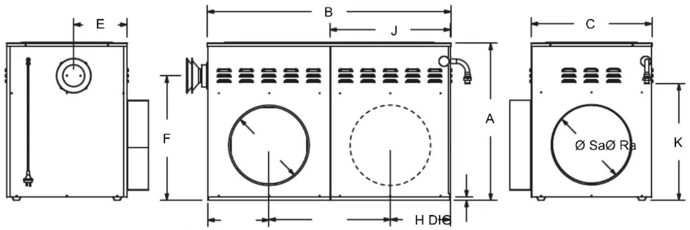
2.1 HEATER DIMENSIONS
| Model A | B | C | D | E | F | G | H | I | J | K | ∅ | Sa | ∅Ra | ||||||||
| KUN521 | 657 | 1046 | 430 | 15 | 104 | 510 | 238 | 187 | 621 | 575 | 423 | 300 | 300 | ||||||||
| KUN530 | 707 | 1096 | 550 | 15 | 240 | 560 | 280 | 280 | 536 | 540 | 474 | 350 | 350 | ||||||||
| KUN415 | 625 | 845 | 397 | 15 | 95 | 495 | 197 | 197 | 446 | 445 | 471 | 300 | 300 | ||||||||
| KUN420 | 625 | 845 | 397 | 15 | 95 | 495 | 197 | 197 | 446 | 446 | 471 | 300 | 300 | ||||||||
| KUN425 | 625 | 845 | 397 | 15 | 95 | 495 | 197 | 197 | 446 | 447 | 471 | 350 | 350 | ||||||||
| KUN430 | 644 | 923 | 549 | 15 | 246 | 515 | 237 | 201 | 483 | 447 | 491 | 350 | 350 | ||||||||
| KUN315 | 627 | 844 | 408 | 15 | 95 | 496 | 230 | 197 | 414 | 445 | 471 | 300 | 300 | ||||||||
| KUN320 | 627 | 844 | 408 | 15 | 95 | 496 | 230 | 197 | 414 | 445 | 471 | 300 | 300 | ||||||||
| KUN325 | 627 | 844 | 408 | 15 | 95 | 496 | 230 | 197 | 414 | 445 | 471 | 350 | 350 | ||||||||
| KUN330 | 645 | 941 | 552 | 15 | 240 | 516 | 236 | 235 | 468 | 470 | 491 | 350 | 350 | ||||||||
All dimension in mm
Diagram 1
2.2 PLATFORM & SERVICE CLEARANCES
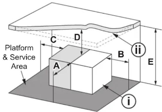
| Minimum Service Clearance | Internal | External | |
| Method 1 | Method 2 | ||
| A = Front | 750mm 750mm 500mm | ||
| B = End | 750mm | N/A | 300mm |
| C = End | N/A | N/A | 300mm |
| D = Top | 250mm 800mm | 1000mm | |
| E = From Platform & Service Area | D + The height of the heater (Heater height = Diagram 1 dimension A) | ||
Diagram 2
i. There are two methods of installing the KUN series internally, in ceilings and under the floor.
Method 1 is for when the minimum clearance (B) at the Fan cabinet end is available.
Method 2 is for when the minimum clearance (B) at the Fan cabinet end is not available.
ii. This minimum clearance height (E) must be maintained across the entire Platform and Service Area.

For all internal installations, permanent artificial lighting shall be provided at the heater, with the switch located at the access opening.
2.3 INTERNAL INSTALLATION
2.3.1 Splitting the Heater
The KUN model heaters can be split for ease of installation. To split the heater, follow these simple instructions.
- Remove the heater's roof after removing the roof screws.
- Disconnect the gas valve, overheat/pressure switch loom, igniter and flame sensor from the control board.
- Disconnect the flue pipe.
- Remove the screws fastening the fan cabinet tabs to the heat exchanger cabinet. These are located at the top of the heat exchanger cabinet on the heater's split line.
- Pivot the fan cabinet upwards high enough to dislodge the lower locking tabs fixed to the fan cabinet near the base.
- The heater is now split in two.
- Protect the exposed looms and tabs from damage while the heater is split in two.
- Once ready, reassemble in reverse order.

Ensure when reassembling the heater that everything is put back and connected correctly.
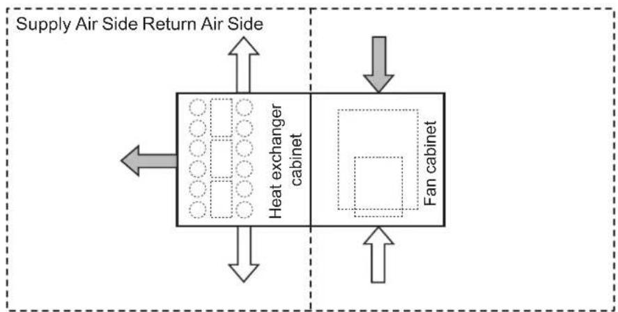
2.3.2 POP Configuration Installation
POP configuration can be changed to suit the installation site, for the preferred and alternative duct connection options refer to Diagram 3.
flowchart
graph TD
    A["Supply Air Side Return Air Side"] --> B["Heat exchanger cabinet"]
    B --> C["Fan cabinet"]
    C --> D["Return air side"]
    style A fill:#f9f,stroke:#333
    style B fill:#ccf,stroke:#333
    style C fill:#cfc,stroke:#333
    style D fill:#fcc,stroke:#333
Plan View
Diagram 3

In "Diagram 3" the grey arrows denote the preferred option and is the factory delivered configuration. The white arrows denote the available alternative options.
2.3.3 Return & Supply Air POP Rotation Procedure
For KUN model heaters the return air POP can ONLY be changed from the front side to back side. The supply air POP can be changed from front to back or end of heater (refer to Diagram 3 page 12).
2.3.3.1 All KUN3, KUN4 & KUN5 Models Return Air POP Rotation Procedure
- Remove screws securing the lid and remove the lid.
- Remove the screws securing the POP panel, blanking panel, and remove panels.
- Swap panels to opposite sides and fasten with the same screws.
- Secure lid with original screws.
2.3.3.2 KUN315, KUN320 & KUN325 Supply Air POP Rotation Procedure
- Remove the screws securing the outer POP plate and remove outer POP plate.
- Remove the screws securing the nominated outer POP blanking plate and remove outer POP blanking plate.
- Remove the screws securing the inner POP blanking plate and remove inner POP blanking plate.
- Relocate and secure inner POP blanking plate in new location.
- Relocate and secure outer POP plate and outer POP blanking plate in their new locations.
- The pressure switch and mounting bracket will need to be swapped to the POP panel that is being exchanged.
2.3.3.3 KUN415, KUN420, KUN425, KUN430, KUN330 Supply Air POP Rotation Procedure
- Remove screws securing the lid and remove the lid.
- Remove the screws securing the POP panel, blanking panel, and remove panels.
- Remove gas feed tube plate and secure to alternate panel.
- Swap panels to nominated sides and fasten with the same screws.
- Secure lid with original screws.
- For the KUN330 ONLY the pressure switch and mounting bracket will need to be swapped to the POP panel that is being exchanged.
2.3.3.4 KUN521 Supply Air POP Rotation Procedure
- Remove the screws securing the outer POP plate and remove outer POP plate.
- Remove the insulation that is beneath the outer POP plate.
- Remove the screws securing the nominated outer POP blanking plate and remove outer POP blanking plate.
- Remove the screws securing the inner POP blanking plate and remove inner POP blanking plate.
- Relocate and secure inner POP blanking plate in new location.
- Insert the outer POP insulation in new location.
- Relocate and secure outer POP plate and outer POP blanking plate in their new locations.
2.3.3.5 KUN530 Supply Air POP Rotation Procedure
- Remove screws securing the lid and remove the lid.
- Remove the screws securing the POP panel, blanking panel, and remove panels.
- Remove POP and blanking panel insulation.
- Remove POP blanking panel and fasten in new location.
- Insert POP and blanking insulation into their new locations.
- Swap panels to nominated sides and fasten with the same screws.
- Secure lid with original screws.
2.3.4 Internal Model Flueing Instructions
General
- All flues must be installed in accordance with AS/NZS 5601.
- Horizontal flues must have a minimum rise of 20mm per 1m run.
- Horizontal flues terminating on a wall must be at least 300mm above ground level.
- An external flue terminal clearance to an opening in a building shall be no less than 1000mm in the vertical direction and 300mm in the horizontal direction.
- Systems with both vertical and horizontal flue runs should be treated as all horizontal.
- 1 × 45^ bend is equivalent to 0.5 × 90^ bend (i.e. 2 × 45^ bends = 1 × 90^ bend).
- Provide adequate support to flue sections (e.g. saddles / strapping).
100mm non-corrosive metal flue.
- Requires a 100mm round single or twin wall non-corrosive metal flue, suitably terminated.
- All flues must have a bolted flue sleeve connection to allow for repairs and/or removal of the appliance.
- Twin Wall flue - maximum flue length of 6m.
- Single Wall flue - maximum flue length of 2m.
- Up to 4 × 90^ elbows are permitted with the same length requirements specified above.
2.3.5 Kaden Remote Flue Terminal
In specific installations, for example under the floor, it is recommended that a remote terminal be used to terminate the flue on the outside wall of the building.
Please refer to instructions supplied with a Remote Flue Terminal (KADEN PART NO. 1621343).
Diagram 4 depicts a typical KUN series heater underfloor configuration.
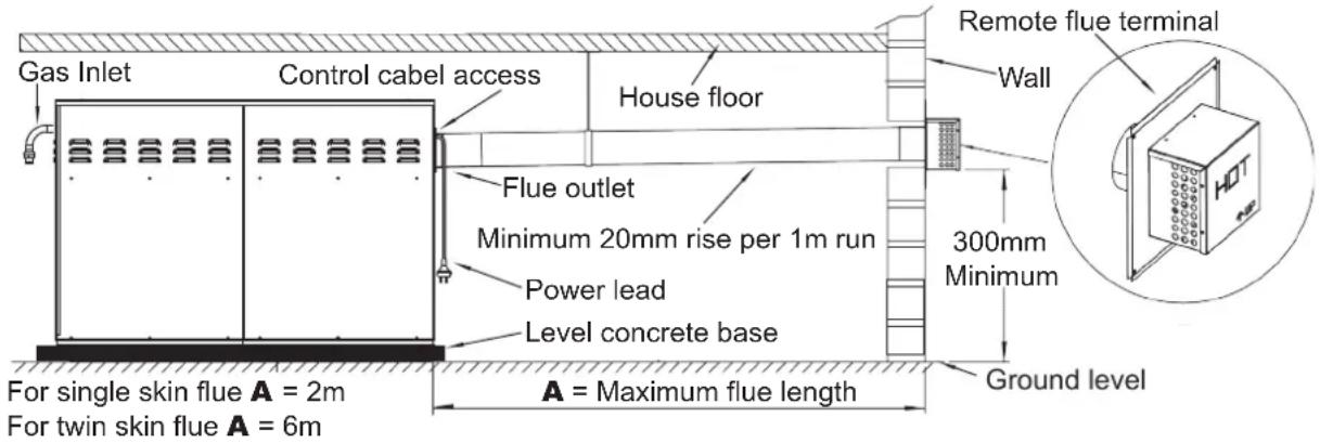
Diagram 4
2.4 EXTERNAL INSTALLATION
2.4.1 Supply Air Overheat Switch Position (KUN530 & KUN330 ONLY)
For external installations of the KUN530 (refer to Diagram 5) and KUN330 (refer to Diagram 6) heaters the supply air overheat switch position must be changed from end discharge to side discharge modify as follows:
2.4.1.1 KUN530
- Disconnect the quick connect terminals (Orange / White) for the overheat switch loom connected from the end discharge overheat switch behind the burners.
- Reconnect the quick connect terminals (Orange / White) to the side discharge overheat switch. These terminals can be identified by the label "SIDE DISCHARGE O/H SWITCH".
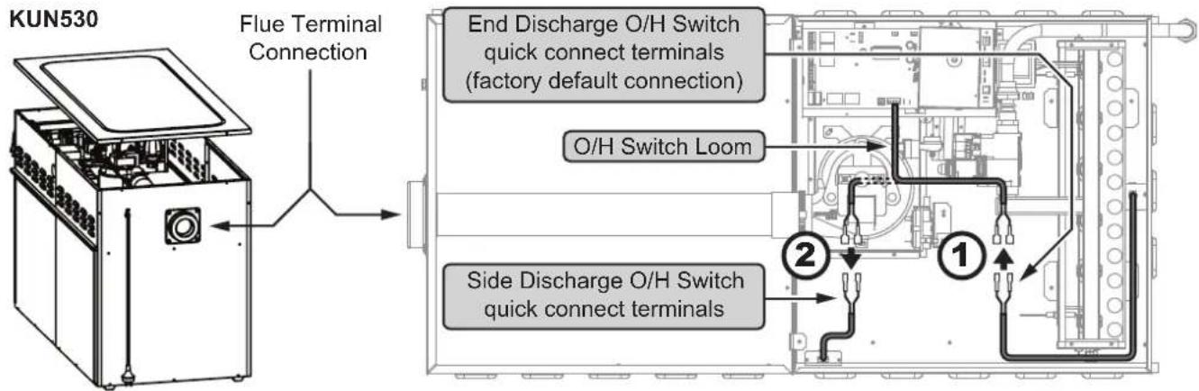
Diagram 5
2.4.1.2 KUN330
- Disconnect the quick connect terminals (Orange / White) for the overheat switch loom connected to the end discharge overheat switch behind the burners.
- The KUN330 is fitted with both left and right side discharge O/H Switches, reconnect the quick connect terminals (Orange / White) to the O/H Switch on the same side the air is supplied from. These terminals can be identified by labels on the sheet metal plate above the burner "LEFT SIDE DISCHARGE O/H SWITCH" or "RIGHT SIDE DISCHARGE O/H SWITCH".
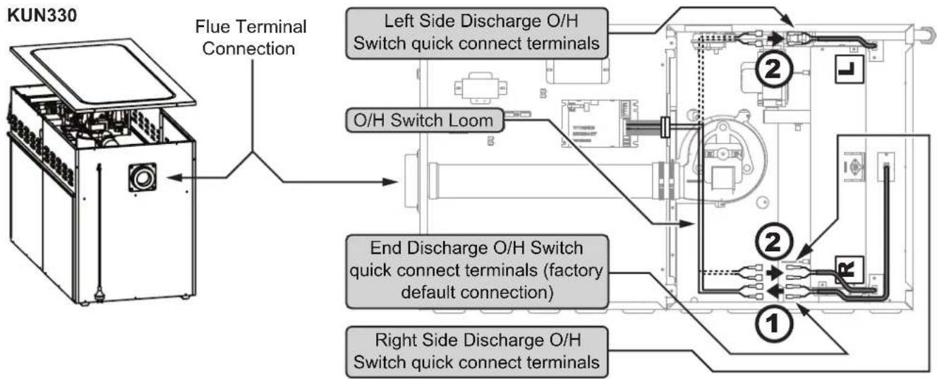
Diagram 6
2.4.2 Modifying KUN Model Duct Orientation
The duct orientation of KUN series heaters can be reversed if the installation requires it. For more information refer to "2.3.3 Return & Supply Air POP Rotation Procedure" on page 13.
2.4.3 Installation of Flue Terminal
The flue terminal for KUN series heaters is not supplied, and MUST BE ordered separately when a KUN series heaters is to be installed externally (KADEN PART NO. 1621303). The flue outlet socket is located on the fan cabinet end of the heater.
- Remove labels and packaging from the flue terminal, thenWall insert into the flue outlet socket.

The flue terminal MUST BE orientated correctly, rotate the flue terminal to ensure that the flue gases are expelled away from the dwelling (refer to Diagram 7).
The flue terminal MUST always be installed before starting the heater.
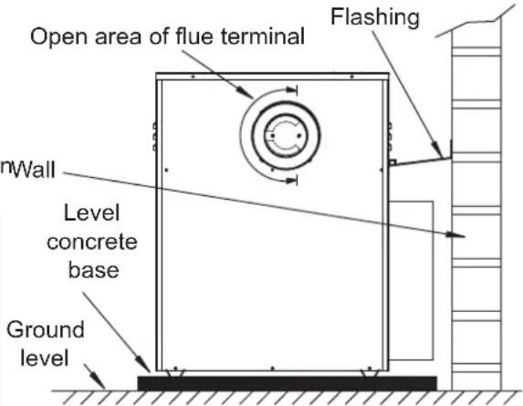
Diagram 7
2.4.4 Flue Terminal Clearances
Heaters should be positioned so that the following minimum clearances exist when measured from the flue edges.
| Clearance | Description |
| 75mm | From the wall against which the heater is mounted.From a drain or soil pipe. |
| 300mm | From a flue terminal, cowl or combustion air intake.Below eaves, balconies or other projections.From the ground, above a balcony or other surface.To a return wall or external corner.Measured horizontally, from an opening window, door, non-mechanical air inlet or any other opening into the building (except sub floor ventilation) or 1500mm in direction of discharge. |
| 500mm | From an electricity meter or fuse box (prohibited area extends to ground level). |
| 1000mm | Measured vertically, from an opening window, door, non-mechanical air inlet or any other opening into the building (except sub floor ventilation).From a gas meter.From a mechanical air inlet, including a spa blower, measured both vertically and horizontally.A flue terminal of this type shall not be located under a roofed area, unless the roofed area is fully open on at least two sides, and a free flow of air at the appliance is achieved. |
Table 3
2.4.4 Area to Cut Out in Wall
When installing the heater at ground level, create two holes to suit the pops all the way to ground level (refer to Diagram 8), or one rectangular hole to cover the distance of both pops ensuring there is no impediment to the structural integrity of the dwelling.
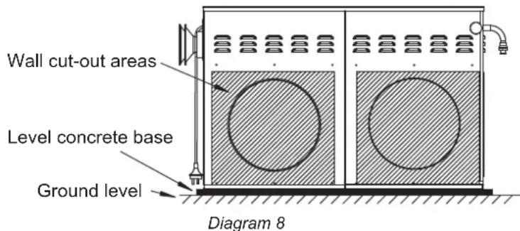

Refer to "2. KUN Universal Model Guidelines" on page 11 to obtain the required dimensions.
2.4.5 Installation of Flashing
2.4.5.1 KUN5 models
Flashing MUST BE fitted to ensure the ductwork is adequately weather protected.

natural_image
Line drawing of a two-door industrial machine with ventilation grilles and door headers (no text or symbols)Step 1. Fit side flashing using existing screws on cabinet sides.

natural_image
Technical line drawing of a mechanical device with two circular components and ventilation grilles (no text or symbols)Step 2. Fit flashing rail using the existing screws from the cabinet.

Step 3. Slide top flashing with fold under flashing rail. Once in place silicone along the upstanding face of top flashing.
natural_image
Line drawing of an industrial machine with control panel and fan (no text or symbols)Step 4. Push the heater up against the wall and secure side flashing to the wall.

It is important to allow for sufficient slack in the ducting connected to the heater's pops, to allow the heater to be moved out from the wall if required for servicing.
2.4.6 KUN3 & KUN4 models

For installation of flashing refer to the instructions provided with the flashing kit.
KUN315, KUN320, KUN325, KUN415, KUN420 & KUN425 use Kaden Part No. 1621299
KUN330 & KUN430 use Kaden Part No. 1621300
2.4.7 Thermistor Installation KUN4 & KUN5
All KUN4 and KUN5 heaters are supplied with a remote thermistor assembly. The thermistor must be installed in the supply air duct, between 1m to 3m away from the heater, but NEVER beyond the first Branch Take Off (BTO) fitting.

Where an Add-On air conditioning indoor evaporator coil is installed, the thermistor MUST BE located in the discharge air POP of the indoor cooling coil.
These installation practices promote more accurate supply air temperature control and optimise heater performance.
- Ensure that there is at least 1 metre of appropriately sized ducting installed between the heater and the first BTO fitting (or evaporator coil).
- Drill a 20mm diameter hole through the top of the inlet end of the first BTO fitting (refer to Diagram 9) or through the top of the evaporator coils discharge POP.
- Carefully insert the thermistor assembly (probe end first) into this hole and secure using the self drilling screw provided. Seal any remaining openings with duct tape.
- Ensure that the thermistor lead is secured to timbers or duct outer casing (refer to Diagram 9) to prevent damage.
Where the first BTO fitting is installed more than 3m away from the heater, an additional duct joiner (installer supplied) will be required so that the thermistor assembly can be fitted correctly. Install the joiner between 1m to 3m away from the heater ensuring that the thermistor can reach this joint. Then follow the steps above as per normal practice.
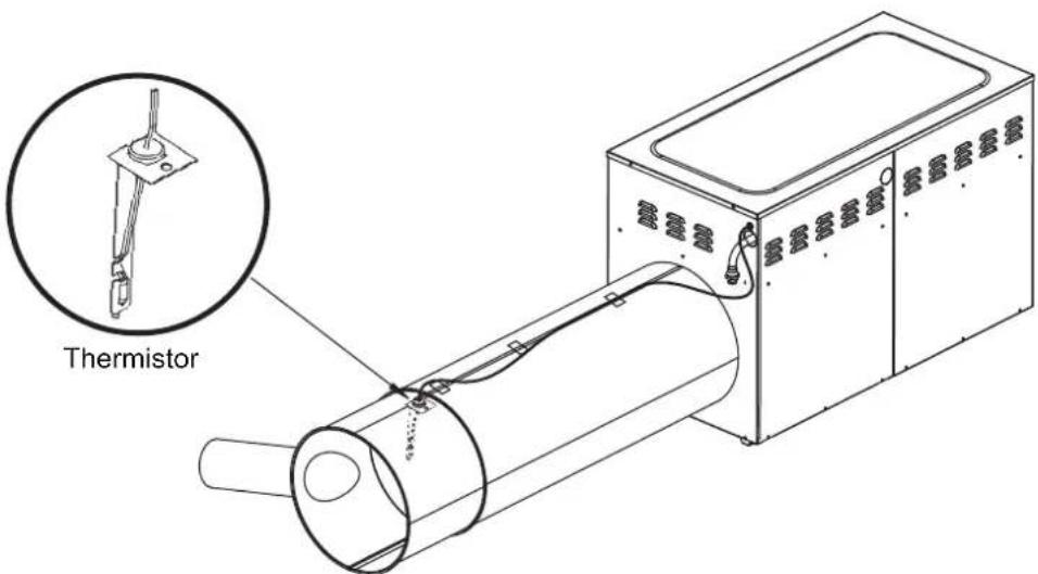
Diagram 9
3. KUN4 & KUN5
KUN4 & KUN5 heaters can be configured for adaptive zoning and / or Add-On Refrigerative Air Conditioning.
There are four 24 VAC relays on the PCB control module, which can be configured either for four zone motors, or for four zone motors and an add-on refrigerative air-conditioning control, refer to Diagram 10 below.
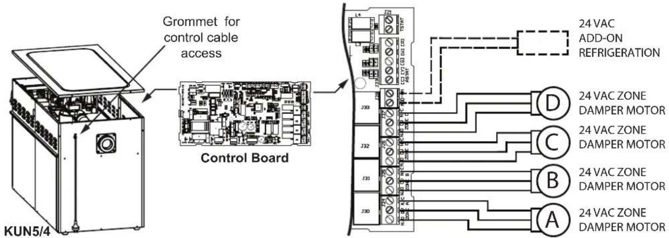
Diagram 10
3.1 WIRING A DAMPER MOTOR TO THE HEATER'S CONTROL MODULE
a. 24 Vac Power Open / Power Close Damper Motor

b. 24 Vac Power Open / Spring Return Damper Motor

c. 240 Vac Power Open / Power Close Damper Motor

Diagram 11
3.1.1 Damper Motor Connections
All KUN4 and KUN5 series gas ducted heaters come with four RJ12 socket connectors preconfigured for Belim® 24V damper motors.
3.1.2 RJ Socket Connections
The plastic cover on the PCB includes moulded cut-outs to enable access to the RJ12 socket. For each socket to be used, press out and remove the cut-out and connect the RJ plug from the Belimo® damper motor.
If not a Belimo damper motor confirm suitability of the terminal on the damper motor before connecting to the RJ12 socket on the heater PCB. The RJ12 socket in Diagram 12 contains six terminal wires, the left two are connected to Normally Open (N/O) on the 3-way terminal block, the middle two are connected to '0V', and the right two are connected to Normally Open (N/C). Check the installation manual accompanying the damper motor to determine if the RJ12 socket on the heater PCB is suitable.
3.1.3 RJ12 socket detail on heater PCB
Diagram 12 details the Normally Open (NO) and Normally Closed (N/C), Zero Volt (OV) and Normally Open (N/O) connections for the RJ12 socket connections for zones A, B, C and D on heater PCB. These connections required to enable the networker outputs to control the damper motors.
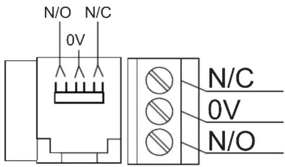
Diagram 12
Note: Ensure that the circuits are correct to Diagram 11 as applicable.
4. KEX EXTERNAL MODEL GUIDELINES
4.1 HEATER DIMENSIONS
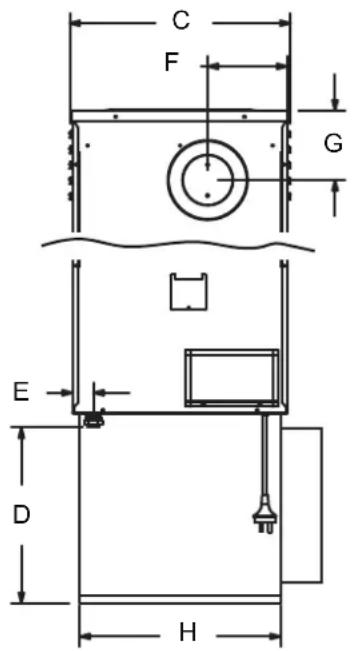
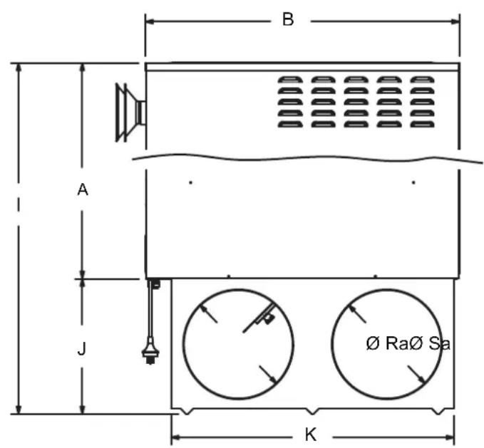
| Model | A | B | C | D | E | F | G | H | I | J | K | |||||||||||||||||||||||||||||||||||||||||||||||||||||||||||||||||||||||||||||||||||||||||||||||||||||||||||||||||||||||||||||||||||||||||||||||||||||||||||||||||||||||||||||||||||||||||||||||||||||||||||||||||||||||||||||||||||||||||||||||||||||||||||||||||||||||||||||||||||||||||||||||||||||||||||||||||||||||||||||||||||||||||||||||||||||||||||||||||||||||||||||||||||||||||||||||||||||||||||||||
| KEX315 | 775 | 850 | 420 | 341 | 41 | 156 | 135 | 391 | 1145 | 370 | 771 | Std | 300 | 300 | ||||||||||||||||||||||||||||||||||||||||||||||||||||||||||||||||||||||||||||||||||||||||||||||||||||||||||||||||||||||||||||||||||||||||||||||||||||||||||||||||||||||||||||||||||||||||||||||||||||||||||||||||||||||||||||||||||||||||||||||||||||||||||||||||||||||||||||||||||||||||||||||||||||||||||||||||||||||||||||||||||||||||||||||||||||||||||||||||||||||||||||||||||||||||||||||||||||||||||||
| KEX320 | 775 | 850 | 420 | 341 | 41 | 156 | 135 | 391 | 1145 | 370 | 771 | 6 | ||||||||||||||||||||||||||||||||||||||||||||||||||||||||||||||||||||||||||||||||||||||||||||||||||||||||||||||||||||||||||||||||||||||||||||||||||||||||||||||||||||||||||||||||||||||||||||||||||||||||||||||||||||||||||||||||||||||||||||||||||||||||||||||||||||||||||||||||||||||||||||||||||||||||||||||||||||||||||||||||||||||||||||||||||||||||||||||||||||||||||||||||||||||||||||||||||||||||||||||
| KEX328 | 894 | 1030 | 579 | 38 | 7 | 41 | 238 | 135 | 55 | 7 | 1280 | 4 | 15 | 951 | Std 350 | 350 | 350 | 6 | 6 | 6 | 6 | 6 | 6 | 6 | 6 | 6 | 6 | 6 | 6 | 6 | 6 | 6 | 6 | 6 | 6 | 6 | 6 | 6 | 6 | 6 | 6 | 6 | 6 | 6 | 6 | 6 | 6 | 6 | 6 | 6 | 6 | 6 | 6 | 6 | 6 | 6 | 6 | 6 | 6 | 6 | 6 | 6 | 6 | 6 | 6 | 6 | 6 | 0 | 0 | 0 | 0 | 0 | 0 | 0 | 0 | 0 | 0 | 0 | 0 | 0 | 0 | 0 | 0 | 0 | 0 | 0 | 0 | 0 | 0 | 0 | 0 | 0 | 0 | 0 | 0 | 0 | 0 | 0 | 0 | 0 | 0 | 0 | 0 | 0 | 0 | 0 | 0 | 0 | 0 | 0 | 0 | 0 | 0 | 0 | 0 | 0 | 0 | 6 | 6 | 6 | 6 | 6 | 6 | 6 | 6 | 6 | 6 | 6 | 6 | 6 | 6 | 6 | 6 | 6 | 6 | 6 | 6 | 6 | 6 | 6 | 6 | 6 | 6 | 6 | 6 | 6 | 6 | 6 | 6 | 6 | 6 | 6 | 6 | 6 | 6 | 6 | 6 | 6 | 6 | 6 | 6 | 6 | 6 | 6 | 6 | 6 | ||||||||||||||||||||||||||||||||||||||||||||||||||||||||||||||||||||||||||||||||||||||||||||||||||||||||||||||||||||||||||||||||||||||||||||||||||||||||||||||||||||||||||||||||||||||||||||||||||||||||||||||||||||||||||||||||||||||||||||||||||||
| KEX415 | 775 | 850 | 420 | 341 | 41 | 156 | 135 | 391 | 1145 | 370 | 771 | Std 300 | 300 | 350 | 350 | 350 | 6 | 6 | 6 | 6 | 6 | 6 | 6 | 6 | 6 | 6 | 6 | 6 | 6 | 6 | 6 | 6 | 6 | 6 | 6 | 6 | 6 | 6 | 6 | 6 | 6 | 6 | 6 | 6 | 6 | 6 | 6 | 6 | 6 | 6 | 6 | 6 | 6 | 6 | 6 | 6 | 6 | 6 | 6 | 6 | ||||||||||||||||||||||||||||||||||||||||||||||||||||||||||||||||||||||||||||||||||||||||||||||||||||||||||||||||||||||||||||||||||||||||||||||||||||||||||||||||||||||||||||||||||||||||||||||||||||||||||||||||||||||||||||||||||||||||||||||||||||||||||||||||||||||||||||||||||||||||||||||||||||||||||||||||||||||||||||||||||||||||||||||||||||||||||||||
| KEX420 | 775 | 850 | 420 | 341 | 41 | 156 | 135 | 391 | 1145 | 370 | 771 | Std 300 | 300 | 300 | 300 | 300 | 300 | 300 | 300 | 300 | 300 | 300 | 300 | 300 | 300 | 300 | 300 | 300 | 300 | 300 | 300 | 300 | 300 | 300 | 300 | 300 | 300 | |||||||||||||||||||||||||||||||||||||||||||||||||||||||||||||||||||||||||||||||||||||||||||||||||||||||||||||||||||||||||||||||||||||||||||||||||||||||||||||||||||||||||||||||||||||||||||||||||||||||||||||||||||||||||||||||||||||||||||||||||||||||||||||||||||||||||||||||||||||||||||||||||||||||||||||||||||||||||||||||||||||||||||||||||||||||||||||||||||||||||||||||||||||
| KEX428 | 894 | 1030 | 579 | 38 | 7 | 41 | 238 | 135 | 55 | 7 | 1280 | 4 | 15 | 951 | Std 350 | 350 | 350 | 350 | 350 | 350 | 350 | 350 | 350 | 350 | 350 | 350 | 350 | 350 | 350 | 350 | 350 | 350 | 350 | 350 | 350 | 350 | 350 | 350 | 350 | 350 | ||||||||||||||||||||||||||||||||||||||||||||||||||||||||||||||||||||||||||||||||||||||||||||||||||||||||||||||||||||||||||||||||||||||||||||||||||||||||||||||||||||||||||||||||||||||||||||||||||||||||||||||||||||||||||||||||||||||||||||||||||||||||||||||||||||||||||||||||||||||||||||||||||||||||||||||||||||||||||||||||||||||||||||||||||||||||||||||||||||||||||||||||||
All dimension in mm
Diagram 13
4.2 SERVICE CLEARANCES
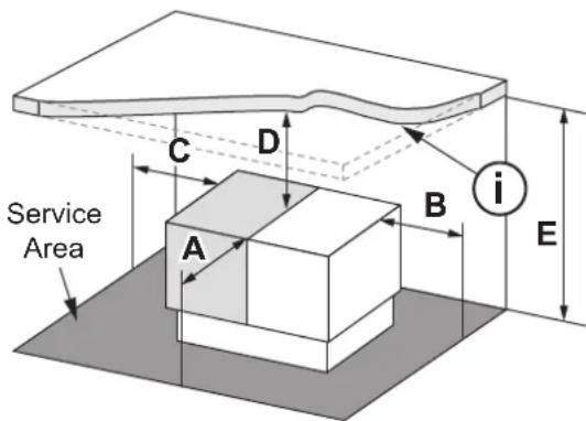
| Minimum Service Clearance | |
| A = Front | 500mm |
| B = End | 300mm |
| C = End | 300mm |
| D = Top | 1000mm |
| E = From Service Area | D + The height of the heater ((Heater height = Diagram 1 dimension I) |
Diagram 14
i. This minimum clearance height (E) must be maintained across the entire Service Area.
4.3 INSTALLATION
4.3.1 Area to Cut Out in Wall
When installing the heater at ground level, create one rectangular hole to suit the total POP width and height, all the way to ground level, (refer to Diagram 15)

Refer to the Base Box for required wall cut out dimensions.

Diagram 15
4.3.2 Installation of Flashing
Flashing MUST BE fitted to ensure the ductwork is adequately weather protected.
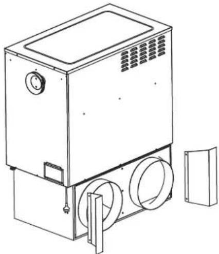
natural_image
Line drawing of a mechanical device with circular components and a side panel (no text or symbols)Step 1. Fit side flashing using existing screws on cabinet sides.
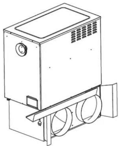
natural_image
Line drawing of a washing machine with two circular fans and ventilation grilles (no text or symbols)Step 2. Slide top flashing under flashing rail on base box
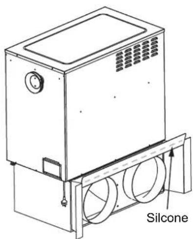
Step 3. Sit top flashing on top of side flashing edges. Once in place silicone along the upstanding face of top flashing.

natural_image
Line drawing of an industrial machine with control panel and door (no text or symbols)Step 4. Push the heater up against the wall and secure side flashing to the wall.
4.3.3 Installation of Flue Terminal
The flue terminal for KEX series heaters is supplied with the heater beneath the lid and above the fan cabinet. Remove and fit to the flue outlet socket located on the fan cabinet end of the heater.

Remove labels and packaging from the flue terminal, then insert into the flue socket outlet
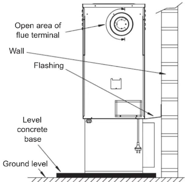
Diagram 16

The flue terminal MUST BE orientated correctly, rotate the flue terminal to ensure that the flue gases are expelled away from the dwelling (refer to Diagram 16).
The flue terminal MUST always be installed before starting the heater.
4.3.4 Flue Terminal Clearances
Heaters should be positioned so that the following minimum clearances exist when measured from the flue edges.
| Clearance Description | |
| 75mm | From the wall against which the heater is mounted.From a drain or soil pipe. |
| 300mm | From a flue terminal, cowl or combustion air intake.Below eaves, balconies or other projections.From the ground, above a balcony or other surface.To a return wall or external corner.Measured horizontally, from an opening window, door, non-mechanical air inlet or any other opening into the building (except sub floor ventilation) or 1500mm in direction of discharge. |
| 500mm From an electricity meter or fuse box (prohibited area extends to ground level). | |
| 1000mm | Measured vertically, from an opening window, door, non-mechanical air inlet or any other opening into the building (except sub floor ventilation).From a gas meter.From a mechanical air inlet, including a spa blower, measured both vertically and horizontally.A flue terminal of this type shall not be located under a roofed area, unless the roofed area is fully open on at least two sides, and a free flow of air at the appliance is achieved. |
Table 4
5. FAN SPEED KUN3, KEX3 & KEX4
5.1 FAN SPEED SETTING FOR KUN3, KEX3 & KEX4 MODELS
There are three fixed fan speed options available on KUN3, KEX3 and KEX4 models, these are:
• High - "HIGH" (Factory Default)
- Medium - "MED"
- Low - "LOW"
5.1.1 To Adjust The Fan Speed
Ensure the power supply to the unit is OFF at the fixed switched socket outlet adjacent to the heater
Access the controls and change as required:
Fan speed high
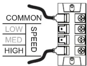
(Factory Default Connections)
Fan speed medium

Fan speed low
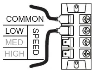
Diagram 17
- For High fan speed do not adjust
- For Medium fan speed move terminal from "HIGH" to "MED"
- For Low fan speed move terminal from "HIGH" to "LOW"
- Turn the power back on once complete

When setting the fan speed ONLY move the HIGH, MED and LOW connection, DO NOT alter the common connection.
6. DUCTING INFORMATION
Good duct design and sizing are essential to every Kaden Central Heating system. Use the Kaden Size Guide and technical data within this manual for the best results and follow these guidelines:
- Ductwork should be well insulated and airtight and have a minimum insulation rating of R1.0 (R1.5 in some areas). Ensure that ducting complies with the Building Code of Australia.
- The ducting should be well fastened to pops, BTO's, outlet boots and neck adapters adequately with duct tape, in accordance with AS 4254 and HB 276.
- It should also be properly sized, and curves and bends should be smooth enough to ensure that the air flows through efficiently, quietly and with minimal resistance.
- The registers and diffusers should be large enough and of good design. They should minimise noise, while providing the correct distribution pattern.
- The positive return air system should be fitted with a grille large enough to accept the full air capacity of the system at low noise levels.
- If the system uses high level outlets (e.g. ceiling diffusers), then the return air inlet should be at a low level. Ceiling systems with a high level return air may result in reduced performance.
- For all Kaden heaters, access to the ductwork must be provided for general maintenance and service to the supply air thermistor sensor where applicable.

It is important that the ducting should be well insulated. It is mandatory under building codes to install insulated, fire rated duct.
If a filter is fitted to the return air grille, it should be easily accessible for regular cleaning. Table 5 gives the minimum recommended return air grille sizes for each model heater to handle the maximum rated airflow.
6.1 MINIMUM RECOMMENDED RETURN AIR GRILLE SELECTION CHART
| Model | Without Filter With Filter | |||
| Grille Size (m2) | Example of Size (mm) | Grille Size (m2) | Example of Size (mm) | |
| KUN521 0.28 400 x | 700 0.42 400 x 1050 | |||
| KUN530 0.36 400 x | 900 0.54 400 x 1350 | |||
| KUN415 0.26 400 x | 650 0.39 400 x 1000 | |||
| KUN420 0.26 400 x | 650 0.39 400 x 1000 | |||
| KUN425 0.26 400 x | 650 0.39 400 x 1000 | |||
| KUN430 0.31 400 x | 800 0.47 400 x 1200 | |||
| KUN315 0.19 400 x | 475 0.28 400 x 700 | |||
| KUN320 0.22 400 x | 550 0.32 400 x 800 | |||
| KUN325 0.24 400 x | 600 0.35 400 x 875 | |||
| KUN330 0.35 400 x | 1000 0.51 400 x 1275 | |||
| KEX415 0.19 400 x | 475 0.28 400 x 700 | |||
| KEX420 0.22 400 x | 550 0.32 400 x 800 | |||
| KEX420XA* | 0.24 400 x 6 | 00 0.35 400 x 875 | ||
| KEX428 0.32 400 x | 800 0.46 | 400 x 1150 | ||
| KEX428XA* | 0.35 400 x 8 | 75 0.54 400 x 1350 | ||
| KEX315 0.19 400 x | 475 0.51 400 x 700 | |||
| KEX320 0.22 400 x | 550 0.32 400 x 800 | |||
| KEX320XA* | 0.24 400 x 6 | 00 0.35 400 x 875 | ||
| KEX328 0.32 400 x | 800 0.46 400 x 1350 | |||
| KEX328XA* | 0.35 400 x 8 | 75 0.51 400 x 1275 | ||
* XA is based on base box POP sizes.
Table 5

Grille sizes are based on maximum airflow with typical Egg-Crate Grille type. For all other types, consult grille manufacturer's specifications. For example a grille with a free ventilation opening measuring 400mm x 750mm, the grille size is 0.4m x 0.75m = 0.3m ^2 . This grille would be suitable for a KUN521 heater provided the grille does not have a filter fitted.
7. OUTLET GUIDE
The "Outlet Register Chart" Table 6 located on page 27 is a guide only and the system's minimum airflow requirements shall be met to ensure reliable operation. The figures are based on using the Kaden Sizing Guide or a system designed using accepted design principles. These figures also relate to typical size registers and diffusers used on domestic heating systems i.e. 300 mm x 100 mm floor registers and 150 mm round ceiling diffusers, with 150 mm ductwork connection.
For all systems, a minimum number of outlets (columns B & C) MUST remain fully open (this includes both the outlet grille and the damper in the duct) to achieve the optimum turn down performance and system reliability without overheating. Similarly, ceiling outlet systems have a maximum number of outlets that can remain fully open, to ensure that the velocity through each outlet is sufficient. These maximum ceiling outlet figures relate to fully open outlets, however, the system will operate efficiently with more outlets open, if it's been properly balanced.
The outlet chart has been divided up into three columns as follows:
A) The maximum number of outlets that should remain fully open for a ceiling outlet system.
B) The minimum number of outlets that should remain fully open for floor/ceiling systems where the system does not have zone dampers installed or, where there are zone dampers but these zones are not operated from a Networker wall control (e.g. wall switches).
C) The minimum number of outlets that should be fully open for floor/ceiling systems where the system has zone dampers installed, and these zones are being operated from a Networker wall control using the heater's onboard zone relays or a zone module. Systems fitting this description are deemed to have Adaptive Zoning active, hence minimum outlet numbers are reduced. Where it shows half figures such as 1.5, it is possible to operate with 1 outlet fully open, and another outlet half closed (such as a bathroom).

There is no maximum number for floor outlets.
Column C only applies to Kaden KUN4 & KUN5 heaters and should not be used unless the Networker has been configured for Adaptive Zoning only. Refer to Column B instead.
If you wish to fit air filters then consult your installer to ensure compatibility with airflow requirements. Ensure that these filters are regularly cleaned and maintained.

RETURN AIR CONNECTION AT MOTOR SIDE OF THE UNIT
On applicable models, connecting the Return Air duct to motor side of the unit will result in reduced air flow. In this situation:
- The total number of outlets normally permitted for a heating system shall be reduced by 2 (refer to the 7.1 Outlet Register Chart - Table 6 located on page 27).
- DO NOT USE this configuration in Add-On Cooling applications, unless you ensure Minimum Recommended Airflow required for the cooling is maintained.
7.1 OUTLET REGISTER CHART
| System Model | Airflow Rate (L/s) | A B C | ||||
| Recommended Maximum Ceiling | Min' Floor / Ceiling | Min' Floor / Ceiling (Adaptive Zoning Only) | ||||
| Universal Heaters | KUN5 | KUN521 785 12 5 1.5 | ||||
| KUN530 1000 17 7 2 | ||||||
| KUN4 | KUN415 620 10 6 2 | |||||
| KUN420 620 10 6 2 | ||||||
| KUN425 630 10 6 2 | ||||||
| KUN430 895 16 7 2 | ||||||
| KUN3 | KUN315 475 10 5 N/A | |||||
| KUN320 540 10 5 N/A | ||||||
| KUN325 650 11 6 N/A | ||||||
| KUN330 895 13 8 N/A | ||||||
| External Heaters | KEX4 | KEX415 (300mm)** 498 N/A 4 N/A | ||||
| KEX420 (300mm)** 581 N/A 5 N/A | ||||||
| KEX420XA (350mm)** 622 N/A 5 N/A | ||||||
| KEX428 (350mm)** 896 N/A 8 N/A | ||||||
| KEX428XA (400mm)** 1012 N/A 8 N/A | ||||||
| KEX3 | KEX315 (300mm)** 498 N/A 4 N/A | |||||
| KEX320 (300mm)** 581 N/A 5 N/A | ||||||
| KEX320XA (350mm)** 622 N/A 5 N/A | ||||||
| KEX328 (350mm)** 896 N/A 8 N/A | ||||||
| KEX328XA (400mm)** 1012 N/A 8 N/A | ||||||
** Model and base box duct size.
Table 6

Airflow figures are based on a total static pressure of 125 Pa for 30 & 35 models and 50 Pa for other models.
Kaden Network 516 modules can only be used on KUN4 and KUN5 model heaters for adaptive zoning.
8. WALL CONTROL INSTALLATION
Kaden heating systems can be controlled by various Kaden Wall Controls. The Wall Control is located inside the house and is wired directly to the heater. The wall control monitors the house temperature, and switches the system ON and OFF to maintain a set temperature. So it MUST BE positioned correctly.
- Install in the living area: It is important that the Wall Control is placed in a position that will provide the most accurate reading of the temperature, i.e. in the area most often used for family living.
- Attach on an internal wall: The temperature difference on an external wall can also affect it, so always mount it on an internal wall. Keep the hole in the wall for the wiring as small as possible to prevent draughts from within the wall cavity affecting the temperature setting.
- Get the height right: The Wall Control should be approximately 1500mm above floor level.
- Avoid hot spots: Keep the Wall Control as far away as possible from warm air outlets, radiation from the sun, fireplaces, radio and television sets or warm pipes and duct running in the wall behind it.
- Avoid cold spots: Keep it as far away as possible from draughts caused by doorways, stairwells, windows or return air inlets.
- Avoid dead spots: Keep it away from areas of less than normal air circulation e.g. behind doors, in alcoves or corners.
- Interference from other electrical connections: Ensure the Wall Control and wiring are kept away from other electrical, data and antenna cables. This includes keeping the Wall Control's wiring away from the spark igniter loom within the heater's cabinet.
- Use the right cable: Use a cable of 0.75mm^2 in cross section and less than 100m in length.

DO NOT install the wiring with the power turned on, as the fuse may blow, which would not be covered under warranty.
ONLY use Kaden Wall Controls, as any failure relating to a non-Kaden Wall Control will not be covered under warranty.
ONLY use alkaline batteries in a manual Wall Control. Other types can cause unwanted operation of the heater when the batteries reach the end of their life.

The Kaden Networker controller is used as a Wired Wall Thermostat and is also the interface to set Installer Parameters and obtain diagnostic information on the Kaden KUN4 and KUN5 Ducted Gas Heaters. A spare Networker should be kept on hand for such purposes.
8.1 NETWORKER INSTALLATION KUN4 & KUN5
8.1.1 Wiring the Networker to a KUN4 & KUN5 Heater

The Kaden Networker backing plate has 4 terminal points for the connection of control wires. When connecting, use ONLY the two top terminals marked TW1 and TW2 or ONLY the two bottom terminals also marked TW1 and TW2. NEVER use a combination of top and bottom terminals when connecting to a single appliance.
For example, a Kaden Networker operating a Kaden cooler and a Kaden heater would have the two bottom terminals connected to the heater and the two top terminals connected to the cooler. When there is more than one Kaden appliance connected to a Kaden Networker, always ensure that the TW1 and TW2 polarity is correct at both ends of the wire cable.
Networkers can be wired directly to KUN4 and KUN5 heaters as follows:
- Run a twin wire cable (i.e. figure 8 cable - 0.75mm^2 ) from the heater to the Networker.
- Remove the backing plate from the Kaden Networker by unclipping it at the sides.
- Draw the wires from the wall cavity and feed them through the opening in the backing plate.
- Connect the cable to the terminal connections on the backing plate before mounting it to the wall Diagram 18.
- Mount the backing plate onto the wall and then reassemble the controller.
- Feed the cable through the grommet, located at a cabinet end.
- Connect the other end of the cable to the terminals marked TW1 and TW2 on the heater's electronic control module, refer to Diagram 18.
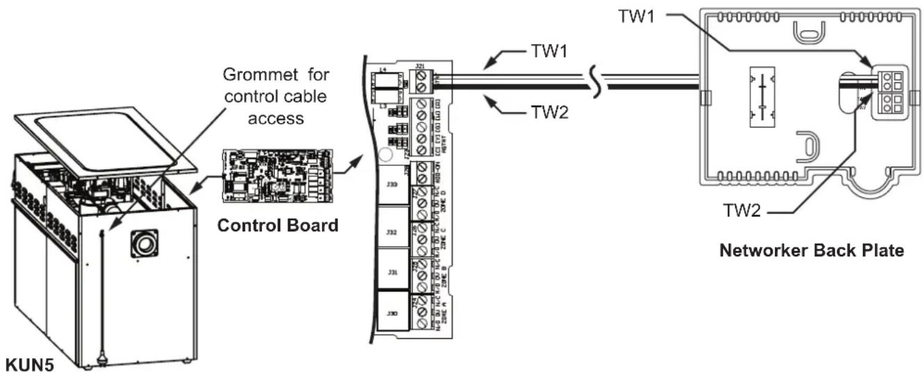
Diagram 18

For Networker connection to KUN3, KEX3 and KEX4 models a Kaden 539 interface is required, Kaden Part No. 1621292
8.2 MANUAL WALL CONTROL INSTALLATION
8.2.1 Wiring the Manual Wall Control to a KUN3 Heater

The Manual control backing plate has 2 terminal points for the connection of control wires. These connections are not polarity sensitive.
A Kaden Manual Wall Control can be wired directly to a Kaden KUN3, KEX3 or KEX4 heater as follows:
- Run a twin wire cable (i.e. figure 8 cable - 0.75mm^2 ) from the heater to the Manual Wall Control.
- Remove the backing plate from the Manual Wall Control by unclipping it from the bottom.
- Draw the wires from the wall cavity and feed them through the opening in the backing plate, remove round knockout.
- Mount the backing plate onto the wall and insert the batteries.
- Connect the cable to the terminal connections to the rear of the thermostat face before mounting it to the backing plate. Refer to Diagram 19.
- Mount the thermostat face onto the backing plate to reassemble the controller.
- Feed the cable through the grommet, located at the end of the heater.
- Connect the other end of the cable to the terminals marked R and W in the heater's electronic control module. Refer to Diagram 19.
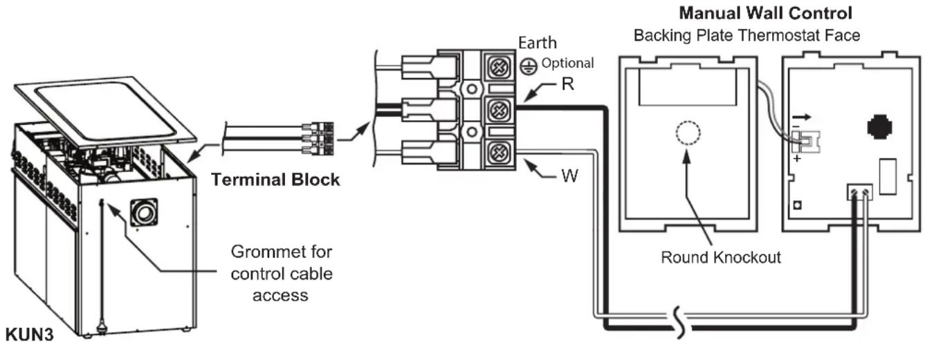
Diagram 19
8.2.2 Wiring the Manual Wall Control to a KEX4 & KEX3 Heaters

The Manual control backing plate has 2 terminal points for the connection of control wires. These connections are not polarity sensitive.
- Run a twin wire cable (i.e. figure 8 cable - 0.75mm^2 ) from the heater to the Manual Wall Control.
- Remove the backing plate from the Manual Wall Control by unclipping it from the bottom.
- Draw the wires from the wall cavity and feed them through the opening in the backing plate, remove round knockout.
- Mount the backing plate onto the wall and insert the batteries.
- Connect the cable to the terminal connections to the rear of the thermostat face before mounting it to the backing plate. Refer to Diagram 20.
-
Mount the thermostat face onto the backing plate to reassemble the controller.
-
Feed your cable through the grommet located at the base of the heater underneath the access panel.
- Connect the other end of the cable to the terminals marked R and W in the heater's electronic control module, refer to Diagram 20.
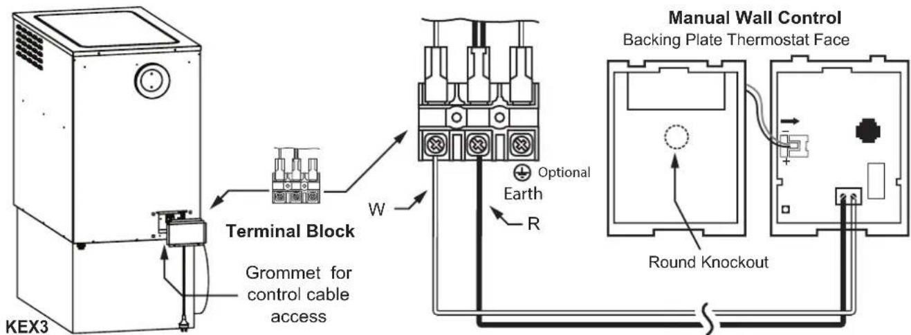
Diagram 20
9. COMMISSIONING KUN4 & KUN5
All Kaden heaters have been factory tested, but should be commissioned and adjusted in accordance with the following instructions to ensure efficient and optimal heating performance.
Remember:
- Switch the mains power OFF before touching any wiring.
- All these steps must be carried out by a qualified trades person.
- If the heater cannot be adjusted to operate in accordance with these instructions, then contact:
1300 4KADEN (1300 452 336) For technical support please call.
9.1 HEATER CONTROL SETTINGS
The NG-3 controller requires a Networker to access and modify installation parameters.
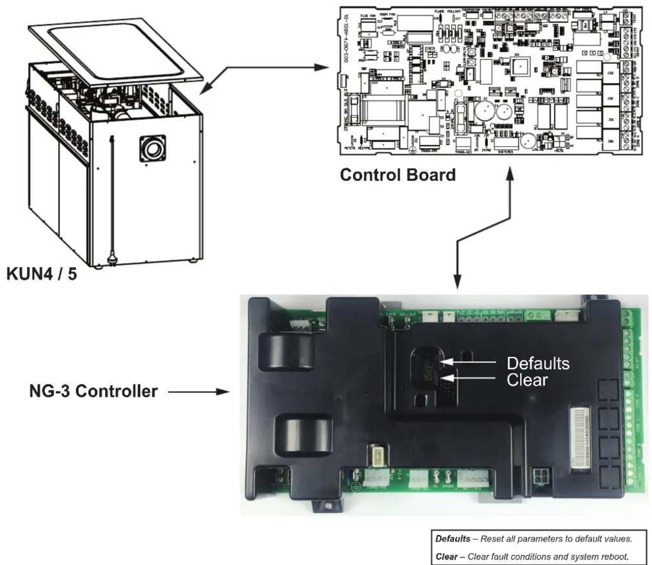
Diagram 21
9.2 INSTALLER PARAMETERS VIA NETWORKER
9.2.1 Networker Installer Parameter KUN4 & KUN5
| No. Display Description | ||||||
| 1 | H01 ID01: 1350 | HEATING: MAXIMUM FAN SPEED SETTINGThe number displayed is the default fan speed setting. That is, the fan RPM setting for normal heating operation. This setting can be adjusted from 500 to 1450 and should be set to meet the installation airflow requirements. It is recommended that a fan speed of at least 1000 be selected as lower speeds are more likely to result in overheating if the system has not been balanced correctly. | ||||
| 2 | H01 ID02: 1350 | COOLING: MAXIMUM FAN SPEED SETTINGThe fan RPM setting for normal cooling operation. This setting can be adjusted from 500 to 1350. | ||||
| 3 | H01 ID03: 950 | HEATING: ZONING MINIMUM FAN SPEED SETTINGThe minimum RPM to which the fan will operate with the maximum number of outlets closed, with the networker zoning in heating mode. This setting can be adjusted from 500 to 1350 (default is 950). | ||||
| 4 | H01 ID04: 1 | HEATER IDENTIFICATION NUMBER(Do not alter unless multiple heaters are installed)In systems with multiple heaters installed, identifies each heater unit in priority order, for example ID04: 1, ID04: 2, ID04: 3. | ||||
| 5 | H01 ID05: 500 | CIRCULATION FAN OPERATIONThe fan RPM setting in circulation mode. That is, fan operation between heating or cooling cycles when the set room temperature has been achieved. | ||||
| 6 | H01 ID06: 65 | SUPPLY AIR THERMISTOR SET POINT TEMPERATUREThe temperature that the heater gas valve modulates to maintain. This setting can be adjusted from 45°C to 70°C (default setting varies between different models) and should be set to provide a comfortable outlet temperature. | ||||
| 7 | H01 ID07: 9 | ZONE/REFRIGERATION /HUMIDIFIER MODE | ||||
| Value | SystemConfiguration | ZoneConnection | Add-OnConnection | HumidifierConnection | ||
| 0 | Heating N/A | N/A N/A | ||||
| 1 | Heating Heater PCB – up to 4 N/A N/A | |||||
| 2 | Heating + Add-On | Heater PCB – up to 4 Heater PCB‘ADD-ON’ terminal | N/A | |||
| 3 | Heating + Humidification | Heater PCB – up to 4 N/A | Heater PCB ‘ADD-ON’ terminal | |||
| 4 | Heating + Humidification + Add-On | Heater PCB – up to 3 (A,B,C)Zone Module – 1 only (D) | Heater PCB ‘ADD-ON’ terminal | N/A | ||
| 5 | Heating Zone Module – up to 4 | N/A N/A | ||||
| 6 | Heating + Add-On | Zone Module – up to 4 | Heater PCB ‘ADD-ON’ terminal | N/A | ||
| 7 | Heating + Add-On | Zone Module – up to 3 | Zone Module ‘ADD-ON’ terminal | N/A | ||
| 8 | H01 ID08: 1000 | COOLING: ZONING MINIMUM FAN SPEED SETTINGThe minimum RPM to which the fan will operate with the maximum number of outlets closed, with the networker zoning in heating mode.DO NOT SET BELOW 1000 | ||||
| 9 | H01 ID09: 0 | DO NOT ADJUST | ||||
| 10 | H01 ID10: 30 | Damper motor Open/Close time can be adjusted between 5 and 240 seconds - factory default 30 seconds | ||||
Table 7

The Kaden Networker controller is used as a Wired Wall Thermostat and is also the interface to set Installer Parameters and obtain diagnostic information on the Kaden KUN4 and KUN5 Ducted Gas Heaters. A spare Networker should be kept on hand for such purposes.
9.2.2 Adjust Networker Parameters
Adjust heater parameters via a networker, as follows:
a. Connect networker, power up unit
b. Press Key 5. 'Clock setting mode' displays. Confirm that the clock display is flashing.
c. Press and hold Key 2 and Key 4 until 'Installer parameter access' displays.
d. After the message clears, press the mode key (M) to toggle between networker parameters (n01), and heater parameters (H01). If more than one networker or heater unit is configured in the system, repeatedly press the mode key until the desired heater unit is selected, e.g. H01 ID01: 1.
e. Press Key 1 or Key 2 to scroll through, and select, the required parameter ID, e.g. H01 ID01: 1 (refer to Table 7 on page 33). (Key 1 = next ID, Key 2 = previous ID.)
f. Turn the rotary dial to adjust the parameter value, e.g. H01 ID01: 1.
g. Press the on/off button to save and exit.

All settings are saved automatically when the on/off button is pressed to exit networker set-up mode.
9.3 KUN4 & KUN5 COMMISSIONING INSTRUCTIONS
With a correctly designed and installed ducted system, generally, the balancing damper in an outlet should be initially set as follows:
• Living areas 100% open
- Bedrooms 50% open
- Bathrooms, ensuite & Laundry: 25% open
9.3.1 Initial Ignition and Gas Inlet Pressure Check
- Disconnect the power supply from the system at the power point.
- Connect a networker to enable access to the heater installation parameters.
- Locate the inlet gas pressure test point and loosen the captive screw three full turns anti-clockwise. DO NOT remove the screw.
- Attach a manometer to the inlet gas pressure test point on the gas valve (refer to the label on the gas valve for the test point location).
- Purge air from the gas piping and turn on the gas at the supply tap.
- Connect and switch on the 240V power supply at the power point.
- Turn on the thermostat and set the temperature to maximum (see the Owner's Manual for operating instructions). Ensure that all zones (if any) are open. It should be possible to see the burners operating at the heater.

If there is air in the gas line, the heater may not ignite on the first attempt. Ignition attempts will occur automatically. Allow time for the heater to rectify itself as it may simply be purging air. If ignition is not successful, the heater will cease ignition attempts and lock out with an error code. If this occurs, take note of the code and reset the heater (refer to the Operation manual).
Initially the fan will run at a low speed (approximately 500 RPM) and then ramp up to the preset fan speed for heating (refer to Table 7, Item 1).
- Wait for the heater to operate for at least 1 minute and then measure the gas inlet pressure. While all other gas appliances are operating at full capacity, the gas pressure must not, at any time, fall below:
• 1.1 kPa for NG models
If the pressure cannot be maintained above these measurements, then the incoming gas supply is inadequate. Check the supply pipe for blockages, and check the gas pipe and meter sizing.
- Switch off the heater, remove the manometer, and tighten the captive screw at the inlet gas pressure test point.

THE GAS VALVE SHOULD NOT BE ADJUSTED UNDER ANY CIRCUMSTANCES.
If everything seems to be functioning correctly up to this point, please continue on with the commissioning procedure. KUN4 & KUN5 heaters will automatically reattempt ignition a few times should the ignition process be unsuccessful, so give the heater time to rectify itself. It may simply be purging any remaining air through the gas components. In any event, the heater will cease ignition re-attempts and lock out with an error code if there is any problem that it can't rectify itself. If the heater does lock out with an error code, please make a note of the code then reset the heater (see the Owner's manual).
9.3.2 Heater Fan Speed and Temperature Settings
The next part of the procedure requires you to set the heating settings to suit the installation. The settings are critical to provide adequate and efficient heating for the installation.
- Ensure that the wall control is still set much higher than the actual room temperature.
- Set the fan speed to suit the installation, adjusting it to provide sufficient but not excessive airflow. Remember, typically the fan speed is less for floor outlet systems than for ceiling outlet systems. With down-vent type ceiling diffusers, airflow in main living areas should be able to be felt down near floor level.
- For new system installations (not changeovers) you should not need to adjust the thermistor set temperature. This setting should only be adjusted if the system is NOT achieving the following temperature rise; ceiling outlets: 25^ to 30^ C and floor outlets: 35^ to 40^ C. This temperature rise is measured from the closest outlet to the heater, minus the return air intake temperature. (i.e. with a return air intake temperature of 20^ C the temperature at the closest floor outlet to the heater should not register more than 60^ C). This temperature rise should never exceed 45^ C.
- For changeovers, commission the new unit to best replicate the original units performance.
If the desired temperature rise is too low or too high the following adjustments may be required.
Increase the room set temperature to maximum to turn the heater on and watch the thermistor temperature until it stabilises.
Ideally, the fan speed setting should be sufficient for the heater to operate at full capacity, when all of the outlets are open and balanced as described previously. The gas rate will then be maintained at the maximum rate during the initial heating cycle, and will only decrease (modulate) the gas rate once the supply air temperature has been reached on subsequent heating cycles. This will initially allow the heater to increase the house temperature at a faster rate to maintain the customer's desired temperature level.
So, with a floor outlet system, which usually requires a low fan speed, you may have to increase the thermistor set temperature to achieve a 35^ to 40^ C rise and avoid modulation. If the heater still reaches the thermistor set temperature or the rise is greater than 40^ C, increase the fan speed.
With a ceiling outlet system, which usually requires a higher fan speed, it is unlikely the heater will reach the thermistor set temperature and modulate. However, if it does, increase the thermistor set temperature and/or increase the fan speed to achieve a 25^ to 30^ C rise and avoid modulation. If the temperature rise is above 40^ C investigate the reason:
- Small number of outlets on the system.
- Restrictive or poorly balanced ductwork.
- Oversized heater for the installation.
- Inadequate fan speed or thermistor set point.
Systems that have zone damper motors that are being operated from the Kaden Networker (Adaptive Zoning) will require the zone minimum fan speed to be set to suit the duct system. This ensures optimum performance from the Adaptive Zoning functions within the heater. To do this:
- Go to the Kaden Networker and close all but one zone. If the system does not have a common zone, leave only the zone key that operates the least number of outlets turned ON (ensure this zone does not have less than the minimum number of outlets required for the heater size). If the system has a common zone then all zone keys can be turned OFF.
- Adjust the fan speed setting to provide the required amount of air from the remaining open outlets. Ensure that the temperature rise does not exceed 45^ C. Do not adjust the thermistor set temperature while setting up the fan speed.
9.3.3 Final Checks
- Check the temperature rise through the heater. The temperature of the warm air at any outlet should not be more than 45^ above the return air temperature. If it is, the heater will be approaching an overheat situation.
- Check that the fan continues to run while the gas burner is operating.
- Check that the fan operates in fan only mode, by operating the Kaden Networker in fan only mode (see Owners Manual).
- Ensure the required gas inlet pressure is supplied at all times during the heater's operation (this should be with all other gas appliances operating at the same time and at their full capacity).
- Go back to the wall control and press the ON/OFF button to turn the heater off.
- Ensure that the burners and fan turn off, then turn off the gas supply at the supply tap and remove the manometer hose from the inlet test point on the gas valve.
- Tighten the inlet test point screw, turn on the gas supply at the supply tap and test for leaks using a soapy water solution or leak detector spray.
- Replace the heater's roof, and then proceed to instruct the customer on the correct operation of the system and assist the customer with filling in the Warranty Card details enclosed in the Owner's Manual.
- Issue any required documentation to the relevant people/authorities in regard to the installation of the heater, the gas connection and power supply. For example, a Certificate of Compliance and Certificate of Electrical Safety.
9.4 FAULT CODE IDENTIFICATION ON HEATER PCB
If the heater fails to start the fault may display on the heater control board with a dual L.E.D flash sequence. The two L.E.D's that display the fault code are 'PRIMARY STATUS L.E.D 1' and 'PRIMARY STATUS L.E.D 2'. Refer to Diagram 22 for location of these status L.E.D's in reference to the 'CLEAR' and 'DEFAULT' buttons on the heater control board cover.
9.4.1 NG-3 L.E.D Identification
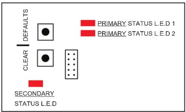
Diagram 22
The ‘PRIMARY STATUS L.E.D 1’ shows the first digit (tens) of the fault code and ‘PRIMARY STATUS L.E.D 2’ shows the second digit (ones), e.g. fault code 35 would display as 3 flashes on ‘PRIMARY STATUS L.E.D 1’ and 5 flashes on ‘PRIMARY STATUS L.E.D 2’.
Both L.E.D's will flash together for the first three flashes and then 'PRIMARY STATUS L.E.D 1' will stop while 'PRIMARY STATUS L.E.D 2' will flash two more times, example flash sequence below.
Primary Status L.E.D 1
Primary Status L.E.D 2

natural_image
Grid of eight red rectangular blocks arranged in two rows and three columns (no text or symbols)Some error codes that may be encountered during installation are detailed in Table 8 below.
9.4.2 Error codes associated with installation
| Fault Code Primary L.E.D 1 Flashes | Primary L.E.D 2 Flashes | Description |
| 30 3 0 Fan Lamp Mode | ||
| 35 3 5 Supply Air Thermistor Fault | ||
| 36 3 6 Bad Supply Air Thermistor Location | ||
| 40 4 0 Return Air Overheat | ||
| 41 4 1 Supply Air Overheat | ||
| 48 4 8 Pressure Lost | ||
| 60 6 0 Motor Open Circuit | ||
| 69 6 9 Fuse Blown 24Vac 2A | ||
| 50 5 0 Ignition Lockout | ||
| 51 5 1 Rollout No Gas | ||
| 54 5 4 Rollout Lockout | ||
| 56 5 6 Pressure Switch Stuck Open | ||
| 57 5 7 Pressure Switch Stuck Closed | ||
| 58 5 8 Pressure Switch Fail |
Table 8
To reset the appliance and clear a lockout fault press and hold the 'CLEAR' button for three seconds on the heater control board or reset through a Networker controller if connected.

The Kaden Networker controller is used as a Wired Wall Thermostat and is also the interface to set Installer Parameters and obtain diagnostic information on the Kaden KUN4 and KUN5 Ducted Gas Heaters. A spare Networker should be kept on hand for such purposes.

Ensure to advise the customer to visit www.metaflex.com.au/kaden and complete the online warranty registration for their appliance.
10. COMMISSIONING KUN3, KEX3 & KEX4
10.1 COMMISSIONING INSTRUCTIONS
With a correctly designed and installed ducted system, generally the balancing damper in an outlet register should be initially set as follows:
• Living areas: 100% open
- Bedrooms: 50% open
- Bathrooms, ensuite & Laundry: 25% open
10.1.1 Start & Check Supply Pressure
- Turn OFF the 240 Volt AC power supply at the fixed switched socket outlet adjacent to the unit.
- Ensure the gas cock adjacent to the heater is in the OFF position.
- Locate gas valve inlet pressure test point, remove the grub screw and insert your test point fitting (hose tail 1/8" NPT).
- Attach a manometer to the test point.
- Ensure that all air has been purged from the gas piping and then turn ON the gas cock adjacent to the unit.
- Turn on the 240 Volt AC power supply adjacent to the unit.
- Go to the wall control, turn it ON and increase the temperature setting so that it calls for heat.
- The unit will now attempt to ignite.
- Once the ignition is successful allow the unit to run for one minute, ensuring the gas supply pressure does not fall to below 1.1kPa while other gas appliances are operating at their full capacity.
- If the reading is below 1.1kPa, then the incoming gas supply is inadequate (check supply pipe for blockage, and check pipe sizing and gas meter sizing).
- Turn the unit OFF at the wall control, isolate the gas and the 240 Volt power supply adjacent to the unit.
- Remove and replace test point with the grub screw.

If the unit does not ignite on the first attempt it may be a result of all air not being purged from the gas supply line. The heater will attempt to ignite up to five times before locking out, after which it will require a power reset.
If the heater does not attempt ignition at all:
- Check the Lighting Procedure again and if it still fails to light, by-pass the wall control by removing cables from the terminal block at the unit and link (bridge) terminals "R" and "W". If it then lights, there is a fault with the wires to the wall control or in the wall control itself. If it does not light, check the overheat switch has not tripped or the 2 amp fuse has not blown.
10.1.2 Start & Check Burner Pressure
- Repeat steps 1 to 7 in Section 9.2. For step 3 relocate the test point fitting from the inlet pressure test point to the burner pressure test point on the gas valve, or if fitted use the test point on the manifold.
- Take a manometer reading of the test point pressure and confirm it is equal to the figure shown on the appliance data label. If the pressure reading is not correct, adjust the gas valve pressure regulator either up or down to match the required test point pressure. If the pressure is lower than the required amount and cannot be adjusted any higher, this indicates that the incoming supply pressure is not sufficient (check supply pipe for blockage, and check pipe and gas meter sizing).
10.1.3 Setting the Fan Speed
- KUN3, KEX3 & KEX4 Heaters are fitted with a single speed room fan with High, Medium and Low fan speed options. Refer to Section 4.0 to change the desired fan speed. Set the fan speed to achieve, as close as possible, a temperature rise at the nearest outlet to the heater above the inlet (Return Air) temperature for the type of system as follows:
- Floor Outlet System: 35^ to 40^ C rise (e.g. Return Air temp at 20^ C plus 35^ C rise equals a 55^ C outlet temperature).
- Ceiling or High Level outlet System: 25^ to 30^ C rise. If the outlet air is hotter than recommended then a higher fan speed should be selected to reduce the outlet temperature. If it is lower, then reduce the fan speed.
- For changeovers, commission the new unit to best replicate the original units performance.

The temperature of the warm air at any outlet should not be more than 45^ C above the return air temperature.
10.1.4 Final Checks
Confirm:
- Minimum flowing gas pressure is 1.1 kPa (NG units) with all other gas appliances in operation.
- The burner pressure is as indicated on the appliance data label.
- The temperature of the warm air at any outlet is not more than 45^ above the return air temperature.
- The fan continues to run while the burners are operating.
Once Confirmed:
- Turn the heater OFF at the wall control.
- Ensure that the burners and fan turn OFF, then turn OFF the gas supply at the supply tap and remove the manometer hose and fitting from the pressure test point.
- Replace and tighten the test point screw, turn ON the gas supply at the supply tap, start up the heater again and test for leaks using a soapy water solution or a leak detector spray.
- Replace controls access panel, then proceed to instruct the customer on correct operation of the system and assist the customer to fill in the Warranty Card details.
- Issue any required documentation to the relevant people/authorities in regard to the installation of the heater, the gas connection and power supply. For example, a Certificate of Compliance and Certificate of Electrical Safety.

Ensure to advise the customer to visit www.metaflex.com.au/kaden and complete the online warranty registration for their appliance.
- TECHNICAL SPECIFICATIONS
| Model | Natural Gas | Duct Connection POP Sizes (mm) | Minimum Recommended Return | Airflow @ Total Static Pressure (L/s) | Net Weight (kg) | Fan motor | Total Maximum Current (A) | Maximum Recommended Add-On Cooling Capacity (kW) | |||||||
| Gas Input | Heat Output | ||||||||||||||
| Maximum Input (MJ/hr) | Maximum Output (kW) | No Filter ( m^2 ) | With Filter ( m^2 ) | 50 (Pa) | 75 (Pa) | 100 (Pa) | 125 (Pa) | Power (W) | Current (A) | ||||||
| KUN521 | 90 21 300 | 0.28 0 | 42 785 7 | 65 740 7 | 15 63 3 | 15 4.2 6 | 13 | ||||||||
| KUN530 | 130 | 30 | 350 | 0.36 | 0.54 | 1085 | 1052 | 1030 | 1000 | 85 | 650 | 4.3 | 6 | 18 | |
| KUN415 | 64 15 300 | 0.26 0 | 39 620 5 | 85 555 5 | 30 55 3 | 15 4.2 6 | 10 | ||||||||
| KUN420 | 85 19 300 | 0.26 0 | 39 620 5 | 85 555 5 | 30 58 3 | 15 4.2 6 | 10 | ||||||||
| KUN425 | 98 23 350 | 0.26 0 | 39 630 5 | 95 565 5 | 35 58 3 | 15 4.2 6 | 10 | ||||||||
| KUN430 | 130 30 350 | 0.31 | 0.47 970 | 948 920 | 895 75 | 650 4.3 6 | 15 | ||||||||
| KUN315 | 70 15 300 | 0.19 0 | 28 475 4 | 53 430 4 | 07 48 2 | 50 3.0 4 | 10 | ||||||||
| KUN320 | 90 19 300 | 0.22 0 | 32 540 5 | 25 505 4 | 85 49 3 | 15 3.0 4 | 10 | ||||||||
| KUN325 | 107 23 350 | 0.24 | 0.35 650 | 625 595 | 565 49 | 315 3.8 4 | 10 | ||||||||
| KUN330 | 133 30 350 | 0.35 | 0.51 970 | 948 920 | 895 68 | 600 6.0 6.5 | 15 | ||||||||
| KEX415 | 62 15.5 | 300 0.19 | 0.28 498 | 480 461 | 443 57 | 250 1.8 4 | N/A | ||||||||
| KEX420 | Std | 82 20 | 300 0.22 | 0.32 581 | 561 541 | 521 58 | 315 2.5 4 | N/A | |||||||
| XA* | 82 20 | 350 0.24 | 0.35 622 | 598 574 | 553 58 | 315 2.5 4 | 10 | ||||||||
| KEX428 | Std | 115 28 | 350 0.32 | 0.46 896 | 873 849 | 819 68 | 600 4.4 6.5 | 13 | |||||||
| XA* | 115 28 | 400 0.35 | 0.51 1012 | 985 957 | 921 68 | 600 4.4 6.5 | 15 | ||||||||
| KEX315 | 66 15.5 | 300 0.19 | 0.28 498 | 480 461 | 443 57 | 250 1.8 4 | N/A | ||||||||
| KEX320 | Std | 87 20 | 300 0.22 | 0.32 581 | 561 540 | 521 58 | 315 2.5 4 | N/A | |||||||
| XA* | 87 20 | 350 0.24 | 0.35 622 | 598 570 | 553 58 | 315 2.5 4 | 10 | ||||||||
| KEX328 | Std | 120 28 | 350 0.32 | 0.46 896 | 873 845 | 819 68 | 600 4.4 6.5 | 13 | |||||||
| XA* | 120 28 | 400 0.35 | 0.51 1012 | 985 955 | 921 68 | 600 4.4 6.5 | 15 | ||||||||
* XA is based on base box POP sizes.
The manufacture reserves the right to change specifications without notice.
Table 9
12. TECHNICAL SUPPORT
For technical support please call
1300 4KADEN (1300 452 336)

Product warranty registration forms can be found online at www.metalflex.com.au/kaden or in the owner's manual.
NOTES
NOTES

natural_image
Exterior view of two industrial air purifiers with ventilation grilles and control panels (no visible text or symbols)
- Models
- Table of Contents
- Warnings and Important Information 4
- Scope 6
- General Guidelines 7
- KUN Universal Model Guidelines 11
- KUN4 & KUN5 19
- KEX External Model Guidelines 21
- Fan Speed KUN3, KEX3 & KEX4 24
- Ducting Information 25
- Outlet Guide 26
- Wall Control Installation 28
- Commissioning KUN4 & KUN5 32
- Commissioning KUN3, KEX3 & KEX4 38
- Technical Specifications 40
- Technical Support 41
- WARNINGS AND IMPORTANT INFORMATION
- READ ALL INSTRUCTIONS BEFORE USING THE APPLIANCE.
- INDICATES A RECOMMENDED REQUIREMENT OF THIS MANUAL.
- REGULATORY / INSTALLATION / SAFETY
- SCOPE
- GENERAL GUIDELINES
- INSPECTION
- UNPACKING THE HEATER
- UNLOADING OR LIFTING THE HEATER
- GAS INLET CONNECTION
- ELECTRICAL POWER SUPPLY
- INSTALLATION OF DUCT CONNECTION POPS
- HEATER POSITIONING
- INSTALLATION OF INTERNAL HEATERS
- Installing in the Roof Space
- Installing Beneath the Floor
- INSTALLATION OF INTERNAL HEATERS - ROOM, ENCLOSURE OR PLANT ROOM
- EXTERNAL INSTALLATIONS
- KUN UNIVERSAL MODEL GUIDELINES
- HEATER DIMENSIONS
- PLATFORM & SERVICE CLEARANCES
- INTERNAL INSTALLATION
- Splitting the Heater
- POP Configuration Installation
- Return & Supply Air POP Rotation Procedure
- All KUN3, KUN4 & KUN5 Models Return Air POP Rotation Procedure
- KUN315, KUN320 & KUN325 Supply Air POP Rotation Procedure
- KUN415, KUN420, KUN425, KUN430, KUN330 Supply Air POP Rotation Procedure
- KUN521 Supply Air POP Rotation Procedure
- KUN530 Supply Air POP Rotation Procedure
- Internal Model Flueing Instructions
- General
- 100mm non-corrosive metal flue.
- Kaden Remote Flue Terminal
- EXTERNAL INSTALLATION
- Supply Air Overheat Switch Position (KUN530 & KUN330 ONLY)
- KUN530
- KUN330
- Modifying KUN Model Duct Orientation
- Installation of Flue Terminal
- Flue Terminal Clearances
- Area to Cut Out in Wall
- Installation of Flashing
- KUN5 models
- KUN3 & KUN4 models
- Thermistor Installation KUN4 & KUN5
- KUN4 & KUN5
- WIRING A DAMPER MOTOR TO THE HEATER'S CONTROL MODULE
- Damper Motor Connections
- RJ Socket Connections
- RJ12 socket detail on heater PCB
- KEX EXTERNAL MODEL GUIDELINES
- HEATER DIMENSIONS
- SERVICE CLEARANCES
- INSTALLATION
- Area to Cut Out in Wall
- Installation of Flashing
- Installation of Flue Terminal
- Flue Terminal Clearances
- FAN SPEED KUN3, KEX3 & KEX4
- FAN SPEED SETTING FOR KUN3, KEX3 & KEX4 MODELS
- To Adjust The Fan Speed
- DUCTING INFORMATION
- OUTLET GUIDE
- RETURN AIR CONNECTION AT MOTOR SIDE OF THE UNIT
- WALL CONTROL INSTALLATION
- NETWORKER INSTALLATION KUN4 & KUN5
- Wiring the Networker to a KUN4 & KUN5 Heater
- MANUAL WALL CONTROL INSTALLATION
- Wiring the Manual Wall Control to a KUN3 Heater
- Wiring the Manual Wall Control to a KEX4 & KEX3 Heaters
- COMMISSIONING KUN4 & KUN5
- Remember:
- HEATER CONTROL SETTINGS
- INSTALLER PARAMETERS VIA NETWORKER
- Adjust Networker Parameters
- KUN4 & KUN5 COMMISSIONING INSTRUCTIONS
- Initial Ignition and Gas Inlet Pressure Check
- THE GAS VALVE SHOULD NOT BE ADJUSTED UNDER ANY CIRCUMSTANCES.
- Heater Fan Speed and Temperature Settings
- Final Checks
- FAULT CODE IDENTIFICATION ON HEATER PCB
- NG-3 L.E.D Identification
- COMMISSIONING KUN3, KEX3 & KEX4
- COMMISSIONING INSTRUCTIONS
- Start & Check Supply Pressure
- Start & Check Burner Pressure
- Setting the Fan Speed
- Final Checks
- Confirm:
- Once Confirmed:
- TECHNICAL SUPPORT
- NOTES
Brand : Kaden
Model : KEX315
Category : Heating