Envelope X3 V2 - Synthesizer ACL - Free user manual and instructions
Find the device manual for free Envelope X3 V2 ACL in PDF.

User questions about Envelope X3 V2 ACL
0 question about this device. Answer the ones you know or ask your own.
Ask a new question about this device
Download the instructions for your Synthesizer in PDF format for free! Find your manual Envelope X3 V2 - ACL and take your electronic device back in hand. On this page are published all the documents necessary for the use of your device. Envelope X3 V2 by ACL.
USER MANUAL Envelope X3 V2 ACL
Musical Instruments Manufacture
ENVELOPE X3
User's Manual
Eurorack Synthesizer Modules

text_image
ENVELOPE X3 ATTACK DECAY SUSTAIN RELEASE 1. 2. 3. GATES EG 1 OUT EG 2 OUT EG 3 OUT 1. 2. 3. NCLTABLE OF CONTENTS
- INTRODUCTION
2.WARRANTY
3.INSTALLATION - FUNCTION OF PANEL COMPONENTS
5.CHARACTERISTICS
6.SPECIFICATIONS
1. INTRODUCTION
Audiophile Circuits League. -ENVELOPE X3 contains 3 very fast independent ADSR-Envelopes.
There are 2 different time ranges that are switchable. Every Envelope has got an inverted output.
The Gate-Inputs 2 and 3 are normalized to Gate 1.
(For details about normalization, see section 5. CHARACTERISTICS)
2. WARRANTY
In the event of a fault in use, we will repair or replace it free of charge under the warranty terms stated below. The warranty period is valid for one year from the day of purchase. If repair is necessary, please ask the dealer you purchased it from.
We can not guarantee the incidental damage caused by the breakdown or damage that occurred during use of this product. In addition, warranty will expire in the following cases:
- Failure / damage caused by use of unspecified power supply / accessories.
- Failure / damage caused by incorrect connection or use of power cable.
- Failure / damage caused by improper handling method.
- Failure / damage caused by natural disasters (fire, flooding etc.) and pollution.
- When the cause of breakdown or damage lies in equipment other than this product.
- Failure / damage caused by improper modification, adjustment, parts replacement.
- Failure / damage when used under particularly severe conditions, when loaned/rental/hired out to 3rd party.
Is it a malfunction?
Please read the user's manual carefully and check again. If you think that there is still a problem, please consult the dealer you purchased from or contact us (English).
support@audiophilecircuitsleague.com
3. INSTALLATION
△WARNING
*Always turn the Eurorack unit off and unplug the power cord before plugging the Eurorack power cable.
*When attaching the Eurorack power cable, please be careful not to touch the terminal part.
Connect to the Eurorack's system power supply (+12V) using the supplied Eurorack power cable.
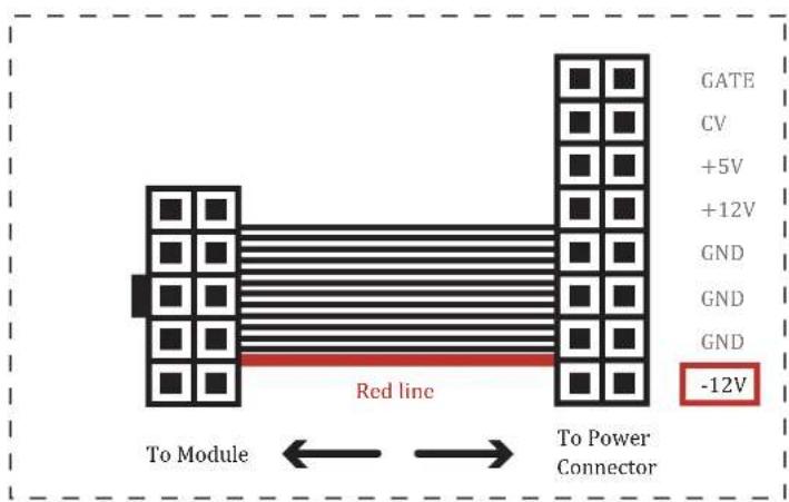
Connect the 16-pin connector to the Eurorack power connector. Connect the red mark on the power cable so that it matches the pin on the (-12 V) side of the power connector.
Connect the 10 pin connector to the shrouded header on the back of the module. The header is protected against reverse-plugging.
text_image
GATE CV +5V +12V GND GND GND -12V Red line To Module → To Power ConnectorFIG.1 : Eurorack power cable
4. FUNCTION OF PANEL COMPONENTS
text_image
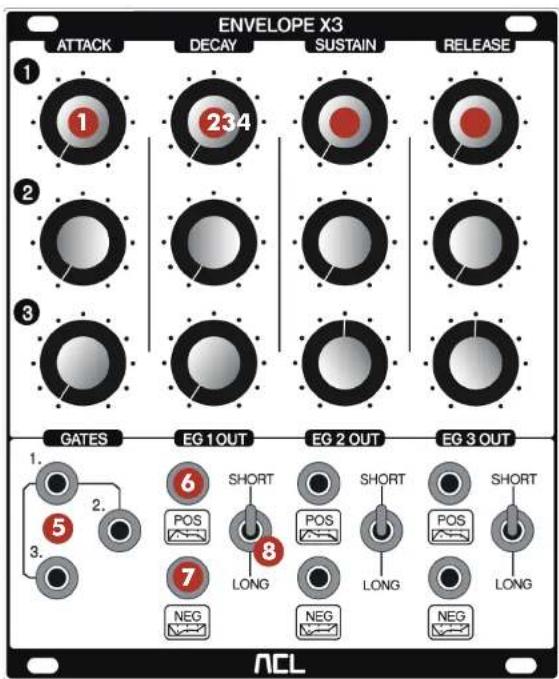
ENVELOPE X3 ATTACK DECAY SUSTAIN RELEASE 1 234 2 3 GATES EG 1 OUT EG 2 OUT EG 3 OUT 1. 2. 3. 6 SHORT SHORT SHORT POS POS POS LONG LONG NEG NEG NEG NCLFIG.2 : Front Panel
① "ATTACK" knob
Adjust the attack time.
② "DECAY" knob
Adjust the decay time.
③ "SUSTAIN" knob
Adjust the sustain time.
④ "RELEASE" knob
Adjust the release time.
⑤ "GATE" input jack
Inputs a GATE signal. When using only GATE 1, it is possible to control EG 1, 2, 3 using one GATE signal without inserting cables into GATE 2, 3 (Normalize). (For details, see section 5.CHARACTERISTIC)
⑥ "EG/POS" output jack
It outputs standard envelope.
⑦ "EG/NEG" output jack
It outputs inverted envelope.
⑧ "SHORT/LONG" switch
It is possible to select the operation speed of the envelope from two ranges.
5. CHARACTERISTIC
GATE input 1 is normalized (internally connected) to GATE 2, 3. "Normalization" means that if you are not using GATE 2 and 3, the input to GATE 1 will be automatically duplicated to GATE 2 and 3. In other words, you can control three ADSR from one cable input(See FIG. 3). This feature economizes the need to duplicate signals using external multiple modules.

flowchart
graph TD
    A["GATE 1."] --> B(( ))
    B --> C["EG 1"]
    B --> D["EG 2"]
    B --> E["EG 3"]
FIG.3: When using only GATE 1 input (Normalized)
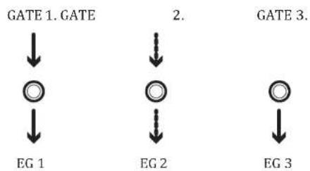
Conversely, when inputs of GATE 1, 2 and 3 are individually plugged in, it is possible to control EG 1, 2, 3 by an independent GATE signal (See FIG. 4).

flowchart
graph TD
    A["GATE 1. GATE"] --> B["EG 1"]
    C["2."] --> D["EG 2"]
    E["GATE 3."] --> F["EG 3"]
FIG.4: When using GATE 1,2,3 inputs (not Normalized)
flowchart
graph TD
    A["GATE 1. GATE"] --> B["EG 1"]
    C["2."] --> D["EG 2"]
    E["GATE 3."] --> F["EG 3"]
FIG.5. When using GATE 1&2 Input, GATE 3 Input is still Normalized to Input 1.
6. SPECIFICATIONS
Power
Eurorack system power supply
Width
21 HP
Depth
22 mm
Power consumption
36mA on +12V / 23mA on -12V
Accessories
- Eurorack power cable x1
- Mounting screws x4