RFYXZ-RSW16 - Speaker Rockford Fosgate - Free user manual and instructions
Find the device manual for free RFYXZ-RSW16 Rockford Fosgate in PDF.

User questions about RFYXZ-RSW16 Rockford Fosgate
0 question about this device. Answer the ones you know or ask your own.
Ask a new question about this device
Download the instructions for your Speaker in PDF format for free! Find your manual RFYXZ-RSW16 - Rockford Fosgate and take your electronic device back in hand. On this page are published all the documents necessary for the use of your device. RFYXZ-RSW16 by Rockford Fosgate.
USER MANUAL RFYXZ-RSW16 Rockford Fosgate
www.rockfordfosgate.com/rtech
Dear Customer,
Congratulations on your purchase of the world's finest brand of audio products. At Rockford Fosgate we are fanatics about musical reproduction at its best, and we are pleased you chose our product. Through years of engineering expertise, hand craftsmanship and critical testing procedures, we have created a wide range of products that reproduce music with all the clarity and richness you deserve.
For maximum performance we recommend you have your new Rockford Fosgate product installed by an Authorized Rockford Fosgate Dealer, as we provide specialized training through Rockford Technical Training Institute (RTTI). Please read your warranty and retain your receipt and original carton for possible future use.
Great product and competent installations are only a piece of the puzzle when it comes to your system. Make sure that your installer is using 100% authentic installation accessories from Rockford Fosgate in your installation. Rockford Fosgate has everything from RCA cables and speaker wire to power wire and battery connectors. Insist on it! After all, your new system deserves nothing but the best.
To add the finishing touch to your new Rockford Fosgate image order your Rockford accessories, which include everything from T-shirts to hats.
Visit our web site for the latest information on all Rockford products;
www.rockfordfosgate.com
or, in the U.S. call 1-800-669-9899 or FAX 1-800-398-3985. For all other countries, call +001-480-967-3565 or FAX +001-480-966-3983.
Table of Contents
2 Introduction
3-9 Installation
12 Warranty
If, after reading your manual, you still have questions regarding this product, we recommend that you see your Rockford Fosgate dealer. If you need further assistance, you can call us direct at 1-800-669-9899. Be sure to have your serial number, model number and date of purchase available when you call.
PRACTICE SAFE SOUND
Continuous exposure to sound pressure levels over 100dB may cause permanent hearing loss. High powered auto sound systems may produce sound pressure levels well over 130dB. Use common sense and practice safe sound.
Safety
This symbol with "WARNING" is intended to alert the user to the presence of important instructions. Failure to heed the instructions will result in severe injury or death.

WARNING
This symbol with "CAUTION" is intended to alert the user to the presence of important instructions. Failure to heed the instructions can result in injury or unit damage.

CAUTION
- To prevent injury and damage to the unit, please read and follow the instructions in this manual. We want you to enjoy this system, not get a headache.
- If you feel unsure about installing this system yourself, have it installed by a qualified Rockford Fosgate technician.
- Before installation, disconnect the battery negative (-) terminal to prevent damage to the unit, fire and/or possible injury.
Contents
• (2) Rear Speaker Wire Harnesses
- Plastic Wire Tie Wraps
Installation Tools
The following is a list of suggested tools needed for installation:
• Security Torx (supplied with Wake Cans)
• Medium Flat Blade Screwdriver
- Ratchet
- 10mm & 12mm Socket
- 4mm Allen Wrench
- Wire Cutters
- Panel Tool
Installation Considerations
This section focuses on some considerations for installing your Yamaha YXZ rear speaker kit. This manual will illustrate the installation process with a 2017 Yamaha YXZ1000R SS with a RFYXZ-RSW16 wiring kit.
If you feel unsure about installing this system yourself, have it installed by a qualified technician.

WARNING
When drilling holes, make sure what is on the other side. Be sure that any electrical, fuel lines or any other important components are free and clear from the area.

CAUTION
Before installation, disconnect the battery negative (-) terminal to prevent damage to the unit, fire and/or possible injury.

CAUTION
Before beginning any installation, follow these simple rules:
- Be sure to carefully read and understand the instructions before attempting to install this wiring kit.
- Consult your UTV's service manual for model specific information. Models may differ from year to year depending on factory options and aftermarket accessories added.
- This wiring kit is specifically designed to work with Rockford Fosgate's PM and RM series of mini wake cans.
- With the addition of an amplifier or source unit, be sure that your current charging system is in proper working order.
- Visit rockfordfosgate.com for more comprehensive product information.
- Visit our YouTube channel for comprehensive installation videos.
Installation Videos

Applicable Models:
2016 & Up YXZ1000R/YXZ1000R SS
This rear speaker wire kit is designed to work with Rockford Fosgate's RFYXZ-K8 and RFYXZ-PMXDK audio kits. The wire harnesses plug directly into PM2652W-MB and RM1652W-MB wake tower speaker enclosures.
NOTE: Some additional interior pieces were removed to make photography easier for documenting the installation process.
natural_image
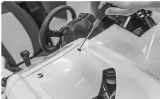
Close-up of a hand using a screwdriver to adjust or install a white vehicle's wheel (no visible text or symbols)Step 1 - Remove Hood
Using a 4mm allen wrench, loosen the screws holding the hood in place and remove the hood from the vehicle.

natural_image
Close-up of a car seatbelt mechanism with a hand adjusting the seat (no visible text or symbols)Step 2 - Remove Passenger Seat
Lift up on the front of the seat to expose the seat mounting bolts.

natural_image
Close-up of a hand using a tool to adjust or install a mechanical component, no visible text or symbolsThere are (4) mounting bolts holding the seat frame in place. Remove these bolts using a 12mm socket and ratchet. Then, lift the seat assembly out.
natural_image
Close-up of a hand adjusting a vehicle chassis component (no visible text or symbols)Step 3 - Center Console Removal
Using your hand, pull up on the backside of the center console to release it.
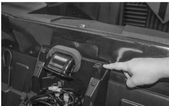
natural_image
Close-up of a hand pointing at a component inside a vehicle's door frame, with visible wiring and components (no text or symbols)NOTE: When removing, be sure to make sure the rubber grommets are in good condition and inserted correctly. If they are not installed properly, the center console will not engage the correct way or attach securely.
natural_image
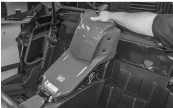
Interior view of an automotive battery pack with visible wiring and components (no text or symbols)Step 4 - Remove Passenger Side Panel
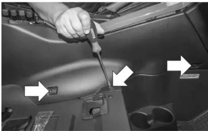
After the center console is out of the way, remove these (5) plastic rivets with a flat blade screwdriver.
natural_image
Close-up of a hand adjusting a car's front panel with sensors and buttons (no visible text or symbols)Once the plastic rivets are removed, lift up on the shifter surround plastic to expose (2) more rivets needed for the removal of the plastic side panel.

natural_image
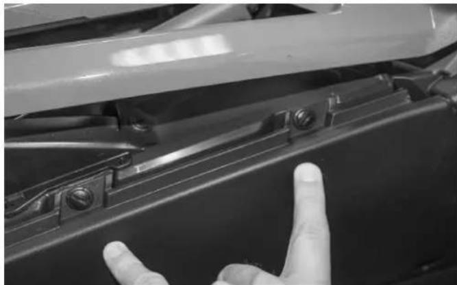
Close-up of a hand adjusting a car seatbelt switch, with two white arrows pointing to the buttons (no text or symbols visible)The passenger side transmission tunnel plastic panel has (3) bolts and (5) plastic rivets securing it to the chassis.
natural_image
Close-up of a hand using a screwdriver to adjust or install a car body panel, with arrows pointing to specific components (no visible text or symbols)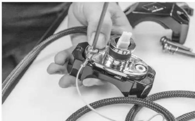
natural_image
Close-up of hands using a tool to adjust or install a mechanical component with coiled cables (no visible text or symbols)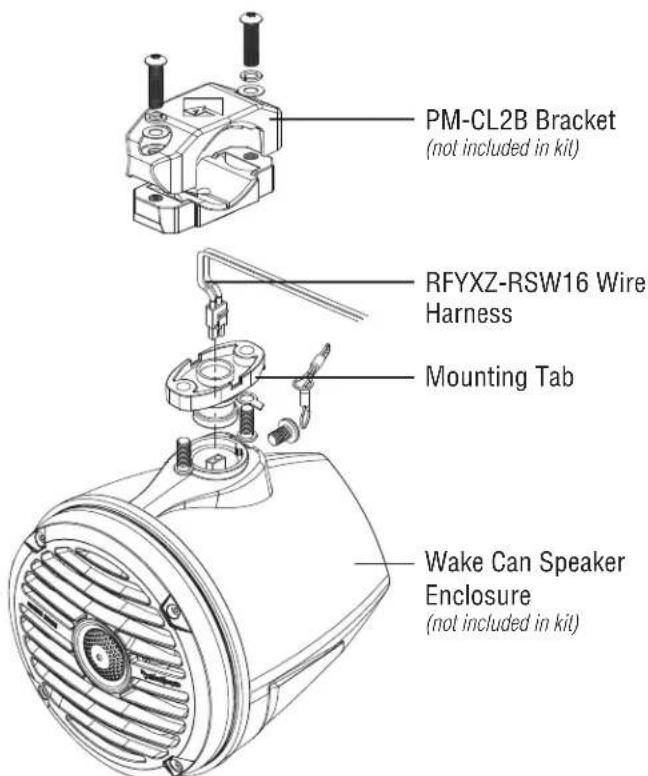
text_image
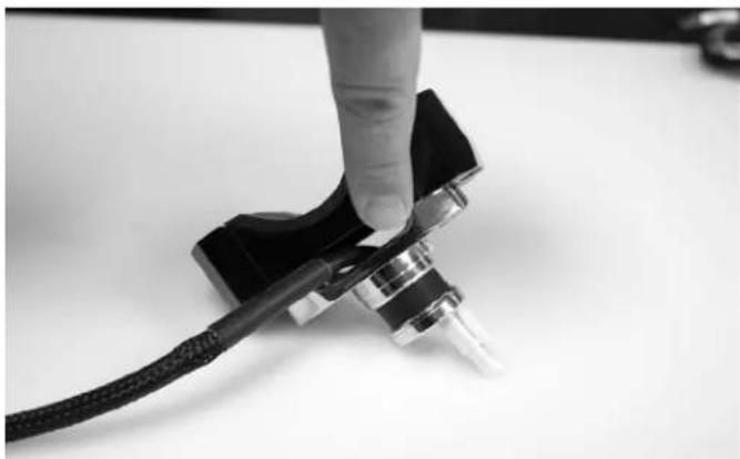
PM-CL2B Bracket (not included in kit) RFYXZ-RSW16 Wire Harness Mounting Tab Wake Can Speaker Enclosure (not included in kit)Step 5 - Assemble Mini Wake Can Speaker Bracket
You will need to assemble the bottom half of the PM-CL2B to the wake can mount first. Start by passing the speaker plug through the T-yoke and assembling it to the lower clamp half with the supplied hardware.
natural_image
Close-up of a hand holding a black cable with a metallic connector, against a plain white background (no text or symbols visible)Place the wire in the notch on the side of the clamp before tightening so the wire does not pinch.
NOTE: Be sure to leave enough slack so you can connect the speaker to the connector.
natural_image
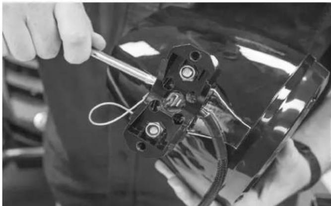
Close-up of hands assembling a mechanical component with wires (no visible text or symbols)Step 6 - Attach Wake Can Speaker Enclosure to Bracket
Align the two pin harness with the connector on the speaker and connect the two together. The wire assembly should be positioned so it exits the clamp from the front side as shown.
Once the wire harness is connected to the wake can, slide the enclosure over the mounting post and secure it with using the security Torx wrench that came with the enclosures.
NOTE: A safety lanyard is supplied with the wake cans for additional safety. Refer to wake can instructions for a more detailed installation guide.
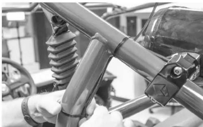
natural_image
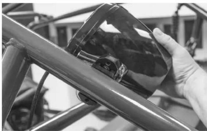
Close-up of a hand holding a transparent plastic object against a blurred background (no visible text or symbols)Step 7 - Mounting Wake Can Enclosure to Roll Cage
Position the speaker/clamp assembly with the speaker to the inside of the roll cage and approximately 4-5 inches behind the rear down tube.
NOTE: There is enough supplied wire length to mount the speaker cans anywhere on the rear down bars.
natural_image
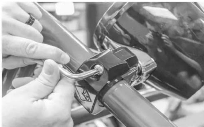
Close-up of hands adjusting a mechanical component with a key inserted (no visible text or symbols)Install the upper clamps assembly using the supplied hardware and security Torx wrench. At this point, position the speaker to its final mounting alignment and tighten the bolts securing it in place.
NOTE: Refer to the PM-CL2B manual for proper torque specs for the clamp bolts to avoid damaging the clamp assembly
natural_image
Close-up of hands installing or adjusting a bicycle wheel assembly with visible insulator and bracket (no text or symbols)Step 8 - Route Speaker Wire Harness
Route the harness down the cage and secure in place with the supplied plastic wire ties.

natural_image
Close-up of a hand inserting cable into a car's seat panel (no visible text or symbols)Continue to route the harness down the rear tube through the panel opening.

natural_image
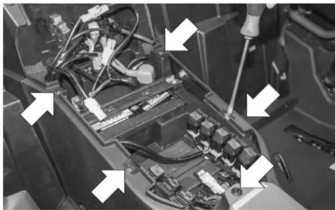
Close-up of a car's engine compartment showing wiring and mechanical components (no visible text or symbols)Route the harness toward the center of the vehicle to the center console.

natural_image
Close-up of a hand holding a cable connector with attached electrical components (no visible text or symbols)NOTE: Be sure to keep away from exhaust and moving components when routing toward the center of the vehicle.
Installation

natural_image
Interior view of a vehicle chassis with visible engine, motors, and wiring (no text or symbols)Be sure that enough of the center console is removed to gain access to the wire harness.

natural_image
Close-up of a car's internal battery compartment showing wiring and components (no readable text or symbols)With both left and right speaker harnesses now pulled through, continue to run down the center console them toward the front of the vehicle.

natural_image
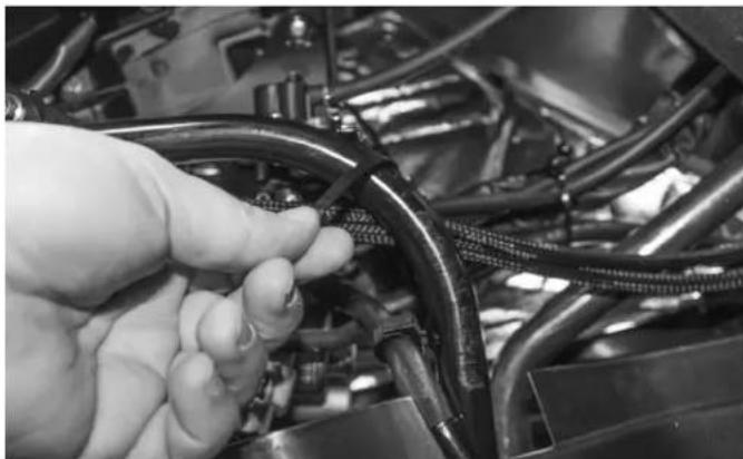
Close-up of electrical wiring and connectors in a mechanical or electrical enclosure (no visible text or symbols)Feed the harness between the panels making sure to pull all available slack through to the center console area.

natural_image
Close-up of a hand holding a cable connector into a vehicle engine compartment (no visible text or symbols)Run the harnesses along the main vehicle wire bundle and secure with supplied plastic wire ties.

natural_image
Close-up of a car engine bay with visible hoses, sensors, and a CPU socket (no text or symbols)Once the slack is pulled through install wire ties to secure the harness in place with the supplied plastic wire ties.
NOTE: Route the harnesses along the back side of the main harness to avoid bulging of the side panel upon reinstallation.
natural_image
Close-up of a hand adjusting automotive engine components with visible wiring and hoses (no text or symbols)Route the harnesses behind the shifter support tube and secure with the supplied wire ties.
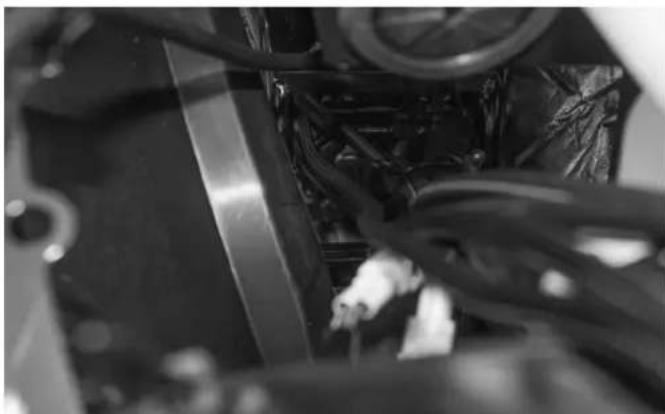
natural_image
Close-up of mechanical components with visible wiring and a central component (no text or symbols)Feed the harnesses up through the transmission tunnel into the hood compartment area.
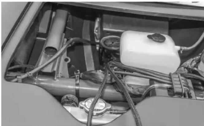
natural_image
Interior view of a vehicle showing internal components like fuel tanks, hoses, and a white plastic tank (no visible text or symbols)Once there, the harnesses are now ready for connection to the RFYXZ-DK radio harness or the RFYXZ-K8 amplifier installation kit harness. Refer to the appropriate installation manual for more information on making these connections.
Rockford Corporation offers a limited warranty on Rockford Fosgate products on the following terms:
Length of Warranty
POWER Amplifiers – 2 Years
BMW® Direct Fit Speakers – 2 Years
PUNCH® & PRIME® Amplifiers – 1 Year
Speakers, Signal Processors, Accessories and Capacitors – 1 Year
All marine, motorcycle, motorsport products - 2 Years
Any Factory Refurbished Product – 90 Days (receipt required)
What is Covered
This warranty applies only to Rockford Fosgate products sold to consumers by authorized Rockford Fosgate dealers in the United States of America. Products purchased by consumers from an Authorized Rockford Fosgate Dealer in another country are covered only by that country's Distributor and not by Rockford Corporation.
Who is Covered
This warranty covers only the original purchaser of Rockford product purchased from an authorized Rockford Fosgate dealer in the United States. In order to receive service, the purchaser must provide Rockford with a copy of the receipt stating the customer name, dealer name, product purchased and date of purchase.
Products found to be defective during the warranty period will be repaired or replaced (with a product deemed to be equivalent) at Rockford's discretion.
What is Not Covered
- Damage caused by accident, abuse, improper installation, operations, theft, water (on non-Element Ready products).
- Any cost or expense related to the removal or reinstallation of product.
- Service performed by anyone other than Rockford or an authorized Rockford Fosgate service center.
- Any product which has had the serial number defaced, altered, or removed.
- Subsequent damage to other components.
- Any product purchased outside the U.S.
- Any product not purchased from an authorized Rockford Fosgate dealer. Refer to rockfordfosgate.com dealer locator for more detail.
Limit on Implied Warranties
Any implied warranties including warranties of fitness for use and merchantability are limited in duration to the period of the express warranty set forth above. Some states do not allow limitations on the length of an implied warranty, so this limitation may not apply. No person is authorized to assume for Rockford Fosgate any other liability in connection with the sale of the product.
How to Obtain Service
Please call 1-800-669-9899 for Rockford Customer Service. You must obtain an RA# (Return Authorization number) to return any product to Rockford Fosgate. You are responsible for shipment of product to Rockford.
EU Warranty
This product meets the current EU warranty requirements, see your Authorized dealer for details.