
MBQX-STG2-RAD-1 - Loudspeaker MB QUART - Free user manual and instructions
Find the device manual for free MBQX-STG2-RAD-1 MB QUART in PDF.

| Product Type | UTV-Tuned Audio Package (Stage 2) |
| Brand & Model | MB Quart MBQX-STG2-RAD-1 |
| Compatible Vehicle | Can-Am Maverick X3 (2017 and up) |
| System Power | 400 Watts Peak, 2-channel Class D amplifier |
| Source Unit | AM/FM/WB, Bluetooth, USB, AUX input, 4x40W peak, 4V preamp outputs |
| Speakers | Two 6.5" coaxial speakers in vehicle-specific dash panels |
| Amplifier Model | NA2-400.2 (2-channel, 400W) |
| Frequency Response | 20Hz - 20kHz (source unit) |
| Audio Features | 8-band graphic EQ, independent subwoofer level & crossover, dual zone, Bluetooth A2DP streaming |
| Radio Bands | AM/FM (USA/Europe), NOAA Weather Band (7 channels) |
| Inputs | USB (charging & audio), AUX (RCA), composite camera input |
| Outputs | Front/Rear/Sub preamp RCA, composite video output |
| Power Supply | 12V DC (vehicle battery), 70A MAXI fuse |
| Installation Time | Approximately 2.5 hours (unmodified vehicle) |
| Weather Resistance | Source unit IPX67 (marine certified) |
| Warranty | 1 year from date of purchase (parts & labor) |
| What's Included | Source unit, mounting panel, wiring harness, amplifier, mounting plate, two speakers in panels, hardware, zip ties |
| Optional Add-ons | Rear speaker pods, 10" subwoofer kit (MBQX-SUB-2), illuminated speaker rings |
| Cutout Diameter (Source Unit) | 3" (76.2mm) |
| Mounting Depth (Source Unit) | 4" (100mm) with bracket |
Frequently Asked Questions - MBQX-STG2-RAD-1 MB QUART
User questions about MBQX-STG2-RAD-1 MB QUART
0 question about this device. Answer the ones you know or ask your own.
Ask a new question about this device
Download the instructions for your Loudspeaker in PDF format for free! Find your manual MBQX-STG2-RAD-1 - MB QUART and take your electronic device back in hand. On this page are published all the documents necessary for the use of your device. MBQX-STG2-RAD-1 by MB QUART.
USER MANUAL MBQX-STG2-RAD-1 MB QUART
natural_image
Black automotive fan assembly with visible motors and control panel (no text or symbols)MBQX-STG2-RAD-1
CAN-AM MAVERICK X3 STAGE 2 / 400 WATT / TWO SPEAKER UTV-TUNED AUDIO PACKAGE
Thanks for choosing MB QUART! The UTV-Tuned Stage 2 Audio System for applicable Can-Am Maverick X3 vehicles (2017 and up) has been meticulously engineered for your vehicle. The process is simple and straightforward. Installation following these detailed instructions can be completed in about 2.5 hours.

INSTALLATION OVERVIEW VIDEO
Many of our vehicle-specific products feature a "how to" install video with additional details on making your installation successful.
Where available, locate your specific video on the website. Type your model number (MBQX-STG2-RAD-1) into the search box, then click on the INSTALL & SUPPORT tab.
WHAT'S INCLUDED
As you unpackage the MBQX-STG2-RAD-1 system, account for all components before attempting installation. Please note some components are included that may not apply to your specific model.
What's In The Box?
- AM/FM/WB, Bluetooth, USB Source Unit with Vehicle-Specific Mounting Panel
- Source Unit Wiring Harness
- Compact 2 channel, Class D 400 Watt Amplifier
- Dual Amplifier Power and Speaker Harness (subwoofer and rear speaker pre-wire included for optional add-on subwoofer and rear speaker kit*)
- Two RCA Audio Patch Cables
- Dual Amplifier Vehicle-Specific Mounting Plate with Hardware
- Two Dash Panel-Mounted 6.5 inch Coaxial Speakers in Vehicle-Specific Replacement Panels
- Power Harness for (optional) Add-On (Second) Subwoofer Amplifier
- One RCA audio extension cable and two RCA "Y" splitters for (optional) Second Subwoofer Amplifier
- Rear Speaker Extension Harness (intended for 4-Door X3 Models and optional rear speaker kit)
- Zip Ties for Securing Audio System Wiring to Vehicle Harnesses
*Optional Rear Speaker Pods and Add-On 10" Subwoofer Kits are found at MBQuart.com
NOTE – Hardware for mounting components (where not reusing OEM hardware) and other installation-related items you will need are contained within the packaging for each piece. Do not dispose of any packaging until you have completely installed your system and are certain you have accounted for every piece. If you feel something is missing, please contact Maxxsonics directly via email – support@maxxsonics.com.
WARRANTY
Your audio system is covered by a 1 year warranty from the date of invoice. It is important to retain your sales receipt. Furthermore, it is crucial that you record and store a record of the serial numbers for each of the components that are included in your system. In the rare instance that a warranty claim is needed both proof of purchase and serial numbers are required. Additional information on the back page.
TECHNICAL SUPPORT
For additional technical information, go to the "SUPPORT" tab at MBQUART.com. There you will find helpful, FAQ, TEQ Tips and you can contact Technical Support via email.
INSTALLATION TIME
About 2.5 hours are required to complete this installation (assuming unmodified vehicle).
TOOLS AND SUPPLIES NEEDED
- Wire Strippers and Crimpers
- Phillips Screwdriver
- Flush Cut Wire Cutters (for trimming zip ties) - Small, Straight (Jeweler's) Screwdriver
● High-Quality Electrical Tape ● Heat Gun or Lighter - Hand-Held Battery-Powered Drill, 9/64" & 1/8" Drill Bits
- Bojo Tools (Non-Marring Pry Tools)
- Ratchet, 8mm Socket
- 10mm Socket (Gauge Cluster/Battery)
- 13mm Socket and 13mm Box Wrench (Seat Removal) - 18mm Socket (Seat Removal)
- 1/2" Socket (Subwoofer Enclosure Front Brackets) - 7/16" Socket (Optional 3rd Amp Plate)
- T-25 and T-27 Torx Drivers (Dash & Housing Hardware) • T-30 Torx Driver (Dash/Console)
Depending on which vehicle-specific UTV-tuned audio system you are installing, you may or may not need all of the tools listed above. You may also own more specialized tools to complete the installation. Share the pics of your installation on our social media channels to help others.
In addition to the tools listed, have music ready for INITIAL TESTING and FINE TUNING steps.
- USB thumb drive with music pre-loaded
- Bluetooth device such as a smartphone with music or a music app
SAFETY PRECAUTIONS
Safely prepare your vehicle for the installation before proceeding.
- Turn the ignition off and remove the key
- Use a packing blanket other soft material to protect your machine
- Safety Glasses - always wear eye protection
- Once all of the seats are removed, disconnect the negative battery cable before proceeding
PREPARATION FOR INSTALLATION & DISASSEMBLY
Before fully dismantling your vehicle, we suggest you prepare all your components, enclosures and wiring harnesses. It increases efficiency to have everything ready when each component is installed. Please note some models with seat belts will require seat belt attachment point removal to remove the whole seat.
REMOVE SEATS - DISCONNECT BATTERY

natural_image
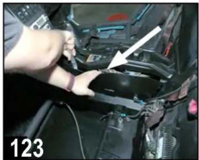
Close-up of a mechanical component with a white arrow pointing to a circular feature, labeled '123' at bottom left (no readable text or symbols beyond label)Slide driver's seat forward and remove two 18mm bolts securing the rear of the seat frame. If the vehicle has factory-installed seats, you can also access these bolts by flipping up the seat cushion (a socket extension is required).

natural_image
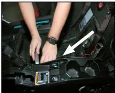
Interior view of a car showing a hand adjusting a seatbelt mechanism (no text or symbols visible)Slide driver's seat back to access front 13mm through-bolts and nuts. Using a socket and box wrench, remove inner and outer front seat hardware. Unplug seat belt sensor.
Remove front driver's seat and set aside with all hardware.

natural_image
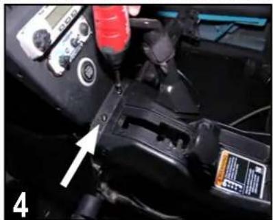
Close-up of a hand using a tool to adjust or install a mechanical component, with no visible text or symbols.Repeat seat removal on front passenger's side (and rear seats - if present). Once passenger seat near battery is removed, disconnect (black) negative battery cable by removing a 10mm bolt and set the negative cable aside.
VEHICLE DISASSEMBLY
This section covers console and dash component removal.
REMOVE CONSOLE SIDES
natural_image
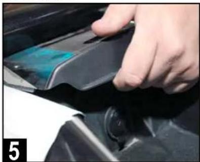
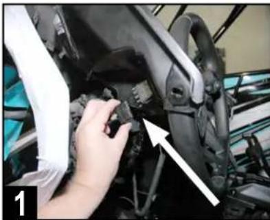
Close-up of hands installing or adjusting a component in a car, with a white arrow pointing to a component (no visible text or symbols)Remove driver's side console side panel using a pry tool from the top to gently release the pressure-fit clips.
natural_image
Close-up of hands installing or adjusting a car engine compartment with a white arrow pointing to a component (no visible text or symbols)Remove passenger's side console side panel using a pry tool from the top to gently release the pressure-fit clips.

natural_image
Close-up of hands installing or adjusting a black plastic component with a white arrow pointing to it (no visible text or symbols)Remove front of center console side panel on passenger's side (footwell area) using a pry tool to gently release the pressure-fit clips.
REMOVE CENTER DASH HARDWARE & CLIPS
natural_image
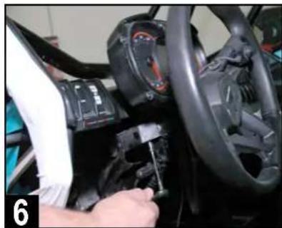
Close-up of a mechanical device with a digital multimeter and labeled component (no readable text or symbols)Move gear selector all the way back (away from the dash). Remove two T-30 screws from the area just forward of the gear selector when in park.
natural_image
Close-up of a hand pressing down on a black mechanical component (no visible text or symbols)Remove top center plastic cover above dash pocket by pushing up on the front pocket edge above the lighter socket, then pulling toward you.

natural_image
Close-up of a hand pressing down on a car tire component (no visible text or symbols)Next, remove two additional T-30 screws located beneath the forward edge of the top center plastic cover location, just forward of fuse box.

natural_image
Interior view of a car showing battery pack, intake manifold, and structural components (no visible text or symbols)Identify four visible push pin clips on the outer edges of the center pocket. These secure the flanges of the left and right side dash speaker panels.

natural_image
Close-up of a mechanical assembly with a white plastic sheet being handled by a metal clamp (no visible text or symbols)Gently remove the four visible push pin clips with a panel removal tool or special panel clip pliers (not needle nose) as shown.
natural_image
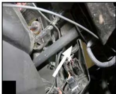
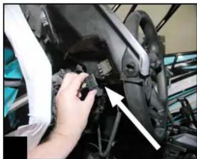
Close-up of a mechanical component with visible wiring and a white arrow pointing to a component (no text or symbols)Remove one additional hidden push pin under the driver's side dash, between the steering wheel and console, just forward of the tubular chassis support.
VEHICLE DISASSEMBLY
This section covers left and right side top dash speaker panels and gauge cluster removal.
REMOVE PASSENGER & DRIVER TOP DASH PANELS

natural_image
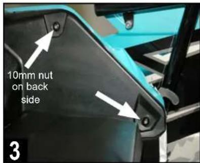
Close-up of a blue car dashboard with a hand adjusting the wheel (no visible text or symbols)Remove gas filler access door on passenger side. Note above the grommet for the retainer clip, there is a 10mm nut attaching a mounting screw.
natural_image
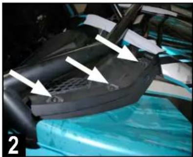
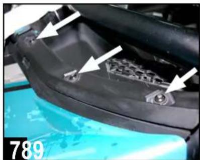
Close-up of a car interior showing a mesh seat and dashboard, with white arrows pointing to specific components (no text or symbols visible)Remove three T-30 screws from the top edge of the passenger's side dash where the hood line meets the dash as indicated.
Remove the remaining two T-30 screws on the side edge of the panel. The top screw requires the 10mm nut loosened with a 10mm socket.
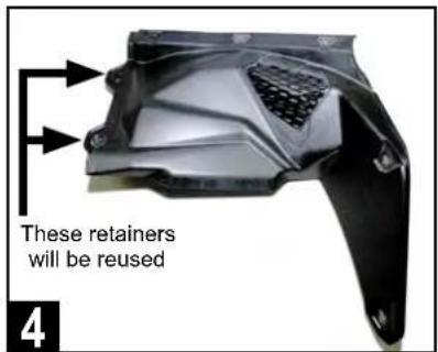
Gently remove passenger side speaker panel and set aside. The center push pin retainer clips will eventually need to be transferred to the new panel.

natural_image
Close-up of a black automotive engine compartment with white arrows pointing to specific components (no visible text or symbols)Drop steering wheel position to access two T-30 gauge cluster screws. Cluster removal helps removal of the panel and access for amplifier installation.
natural_image
Close-up of a car's steering wheel and dashboard with a hand adjusting the gear (no visible text or symbols)Remove two T-30 screws holding the gauge cluster with a 10mm socket (below) and T-30 driver (above). Set gauge cluster aside when done.
natural_image
Close-up of a car's head panel with white arrows pointing to internal components, no visible text or symbolsRemove three T-30 screws from the top edge of the driver's side dash where the hood line meets the dash as indicated.
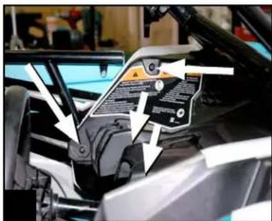
Remove two T-30 screws on the side edge of the panel. Next, remove two remaining T-30 screws behind gauge cluster area as indicated.
natural_image
Close-up of a hand adjusting a mechanical component with an arrow pointing to it (no visible text or symbols)Pull panel* carefully to access switches and unplug them to fully remove driver's side panel. Set aside as with passenger dash panel for later reuse.
*Note: If equipped with Smart-Lok differential feature, remove the module with four 8mm screws from underside of driver's dash panel.
VEHICLE DISASSEMBLY
Removal of the center console inner cover facilitates routing wire harness from bus bar into the dash area.
INNER COVER OF CENTER CONSOLE

Prepare to remove forward inner cover of the center console. Note - some modified vehicles may have aftermarket console electronics present.
natural_image
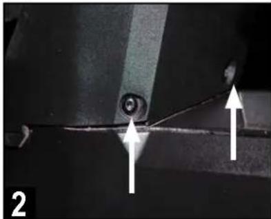
Close-up of a mechanical component with two white arrows pointing to a circular feature, labeled '2' (no text or symbols on the main subject)Remove two T-30 screws on the lower front of center console.
natural_image
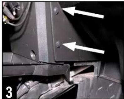
Close-up of a mechanical component with two white arrows pointing to specific features (no text or symbols visible)Finally, remove two push pins on passenger's side of cover panel.
DISASSEMBLY IS COMPLETE!
WIRING HARNESS PREP
The next steps are going to be running the wiring harnesses throughout the console and dash area.
Be sure to lay every harness and cable out to ensure you have identified each one and nothing is missing.
For safety precautions, remove the main 70a MAXI fuse from the black fuseholder in the main power harness at this time. This will prevent the wiring from shorting during the installation work after connecting power at the bus bar in the passenger side center console.

natural_image
Collection of various black and red electrical cable assemblies with connectors, arranged in a grid (no text or symbols visible)The main wiring harness has small red and black wires with mated connectors that enable illumination at the speaker location using optional illuminated speaker rings (not included with this kit). Both the front and rear speaker locations are pre-wired for this feature in the harness to facilitate an easier installation of the illuminated rings. Simply make sure the red and black wires with mated connectors are connected to the front and rear speaker harnesses during the installation of the main wiring harness.
Please check www.MBQuart.com for options if you wish to purchase and install these illuminated speaker rings.
ROUTE WIRING HARNESS
This section covers connecting the main harness to the bus bar in the passenger side center console (toward the back section) and running the various breakout harness sections to their respective locations.
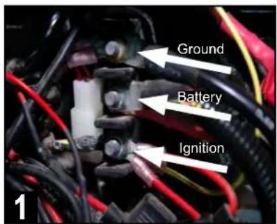
Identify bus bar in passenger side center console. Top is chassis ground, middle is constant +12v power (battery) and bottom is +12v accessory.
natural_image
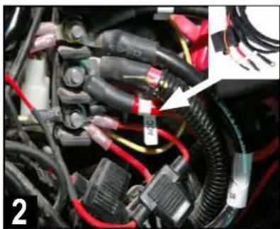
Close-up of automotive electrical connectors and wiring (no visible text or symbols)Connect the ground (black), +12v constant (large red with fuseholder) and +12v ACC (orange) on the audio system harness to bus bar locations.
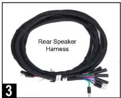
Locate rear speaker harness and lay out next to main harness. Route this harness with the others even if no rear speakers are used at this time.
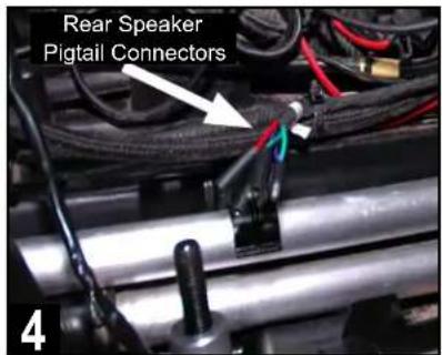
Place the rear speaker harness pigtail connectors just behind the bus bar (about where the rear seat bolt is located) and zip tie in place.
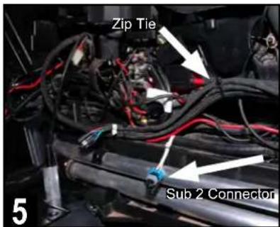
Next, route the rear speaker harness up to join the main & subwoofer harnesses and zip tie in place. Note the "Sub 2" connector stays in that area.
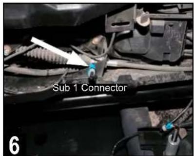
Route the "Sub 1" connector through the console wiring to exit on the driver's side in about the same mid-console location as "Sub 2" connector.
natural_image
Interior view of a vehicle showing wiring and mechanical components (no visible text or symbols)Begin routing the main, subwoofer and rear speaker harnesses along the passenger side console and zip tie to factory wiring.
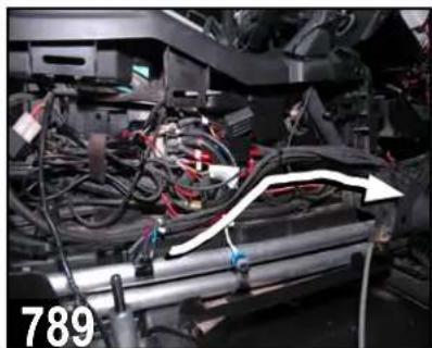
natural_image
Close-up of automotive engine components with a white arrow indicating upward motion (no text or symbols visible)Route the harnesses upward behind the center dash where the panel was removed for easier access. Secure with zip ties to factory wiring.

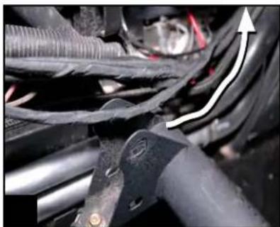
natural_image
Interior view of a car showing exposed electrical components and wiring (no visible text or symbols)Route harnesses up to steering column support bar. Finally, route passenger speaker harness from right speaker location to left harness area.
SOURCE UNIT PREPARATION AND WIRING
This section covers the preparation steps necessary to wire and pre-drill mounting for the source unit.

Remove power plug to facilitate source unit wiring passage by pressing in on the top and bottom retention clips. Or, drill a 1" hole on left side of plug.

Route source unit wiring pigtail and two RCA audio cables to the area where the other harnesses have been routed on the driver's side. Note knotted RCA to designate SUB.

natural_image
Close-up of hands using pliers to adjust cable colors into a car engine (no visible text or symbols)Make four (4) crimped source unit wiring connections by matching wire colors as shown. Tape unused wires.
• RED - +12v Battery (Constant)
• ORANGE - +12v Accessory (ACC)
■ BLUE - Amplifier Turn On
■ BLACK - Chassis Ground
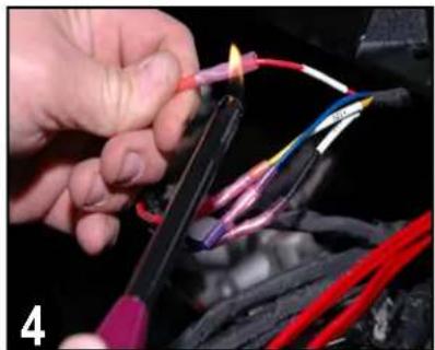
natural_image
Close-up of hands using a tool to wire electrical wires with colored wires (no visible text or symbols)Use a lighter or heat gun to heat shrink and seal the crimped connections. This ensures no moisture will penetrate the wiring.
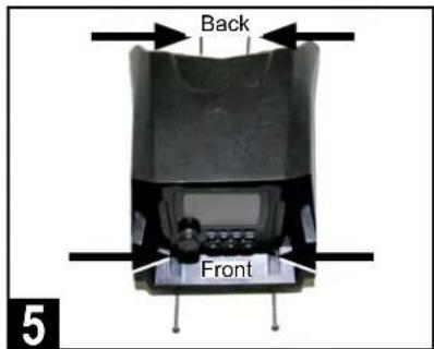
Take note of required drilling holes for mounting of the source unit's housing as shown. Two (2) in front and two (2) at the back.
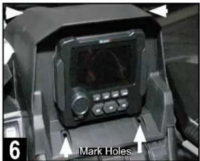
Set source unit housing in place to locate four (4) mounting holes required for final mounting. Locate and mark dimples for verification.
natural_image
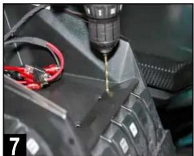
Close-up of a robotic arm with a drill bit and red wiring, no visible text or symbolsUsing a 9/64" drill bit, drill two (2) mounting holes in the dimpled areas as indicated. As the material is plastic, there is very little pressure needed.

natural_image
Close-up of a mechanical device with a drill bit and two cylindrical components, no visible text or symbolsDrill the remaining two (2) mounting holes at the back of the housing as indicated. Again, as the material is plastic very little pressure is needed.
Set the source unit and housing aside until the installation is ready for connections, testing the audio system and final fitting.
Note: If you are adding an optional USB and Auxiliary input accessory plug (model PSAP-2 or PSAP-2S) to the installation, complete that mounting wire run at this time so that upon final installation all wiring is ready to connect to the source unit.
AMPLIFIER INSTALLATION
This section covers installation of the 400.2 amplifier included with the Stage 2 kit, as well as the optional 400.1 subwoofer amplifier in the MBQX-SUB2 add-on subwoofer kit. See page 13 for more details on initial amplifier settings (steps 2 and 3 below).
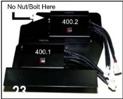
Attach amplifier(s)* to mounting plate with included hardware as indicated. Use only three nuts/bolts on 400.2 (2-ch) amplifier due to tube frame clearance.
*Note: Amplifiers appear upside down, which allows for easier access to adjustments of gain, crossover, etc.
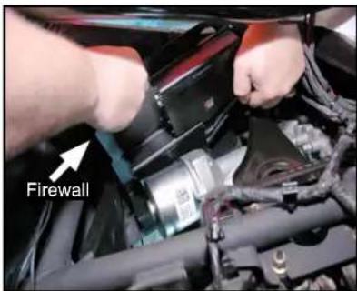
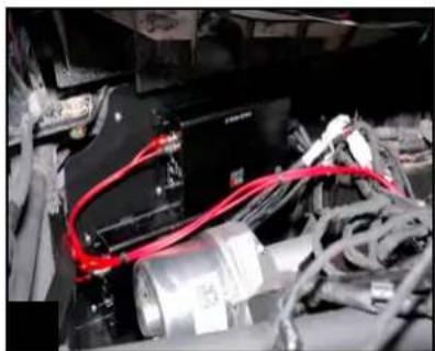
From the top side, place amplifier plate in the intended location behind silver brake booster against the driver's side firewall for test fitting.

Make initial LEVEL and HP crossover settings as indicated on the 400.2 amplifier. Stage 2 kit contains only this amplifier.
• XOVER SWITCH - High Pass (HP)
- LEVEL DIAL - 1/2 of the way up from 9V
■ HP DIAL - Approximately 80Hz
• LP DIAL - Unused in this application

Using a felt marker or punch, mark mounting holes for drilling. There are three holes to mark and drill. Two at the bottom, one at the top corner.
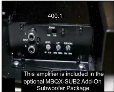
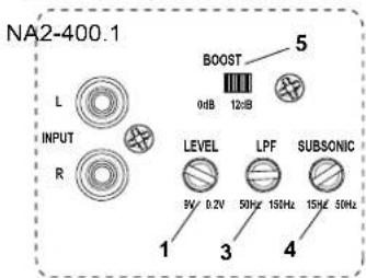
If installing the optional SUB2 add-on, make initial LEVEL, LPF crossover and SUBSONIC filter settings on the 400.1 amp.
- BOOST SWITCH - 0dB Position
- LEVEL DIAL - 3/4 of the way up from 9V
• LPF DIAL - Approximately 100Hz
• SUBSONIC DIAL - Approximately 31Hz

natural_image
Close-up of a hand using a power drill on a car engine component (no visible text or symbols)Drill mounting holes in the marked locations using a 1/8" drill bit. You may wish to remove the amp plate before drilling to avoid scratch marks.

natural_image
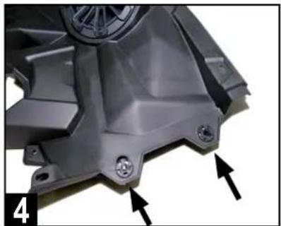
Close-up of a mechanical component with visible internal structure and metal fittings (no text or symbols)Mount amplifier plate in place using the supplied 1/2" length Phillips head sheet metal screws.
natural_image
Close-up of electronic components with red and gray wires, no visible text or symbolsConnect RCA audio cables to the appropriate amplifier according to your designation at the source unit (knotted, labeled, etc.).

Connect the electrical and speaker plugs for each amplifier as labeled*. Tie up excess wiring to factory wires and avoid any moving parts.
*Note: There is a third electrical connector and a "SUB 2" speaker connector intended for the optional second subwoofer option.
OPTIONAL SUBWOOFER INSTALLATION
This section covers the installation of an optional MBQX-SUB-2 add-on 10" subwoofer kit. MB Quart recommends this is installed under the driver's seat, although it can fit under either front seat.
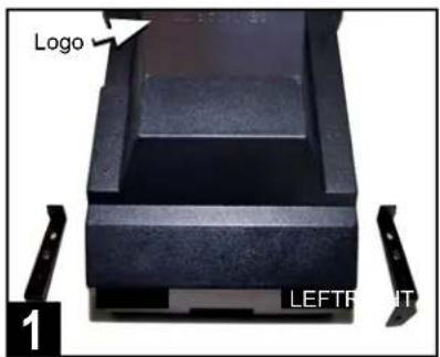
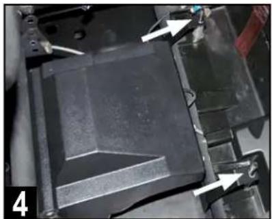
Identify front enclosure brackets. Orientation is referenced to the logo. Left and right are stamped "L" and "R" on the bracket and enclosure.
natural_image
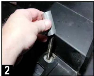
Close-up of a hand inserting a metallic clip into a black mechanical component (no text or symbols visible)Remove the factory-supplied aluminum spacers from rear bolts of seat mounts*. Replace with supplied MB Quart spacers for bracket tolerance.
*Note: If installing into a 4-seat model, these instructions are intended for the front seats only.

natural_image
Close-up of hands installing or adjusting a black electronic component on a car engine (no visible text or symbols)Load subwoofer enclosure into under seat position by angling the front under the support bar for clearance of the brake line and to sit level.
natural_image
Close-up of a mechanical component with arrows pointing to features, no visible text or symbolsAlign rear enclosure brackets over threaded seat mounts so they sit atop the aluminum spacers. Route wiring toward center console area.
Attach front left side mounting brackets to the subwoofer enclosure using two 1/2" bolts and a lock washer on each.
Attach front right side mounting brackets to the subwoofer enclosure using two 1/2" bolts and a lock washer on each.

natural_image
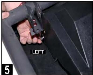
Close-up of a mechanical clamp or bracket component with a white arrow pointing to a specific part, no visible text or symbols.Attach a 1/2" bolt, lock washer and flat (black) washer through the left side seat mount bracket to the threaded insert of the left enclosure bracket.

natural_image
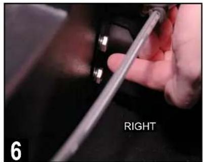
Close-up of a mechanical assembly with a metallic component and a white arrow pointing to a component labeled 'RIGHTLEP' (no readable text beyond label)Attach a 1/2" bolt, lock washer and flat (black) washer through the right side seat mount bracket to the threaded insert of the right enclosure bracket.
natural_image
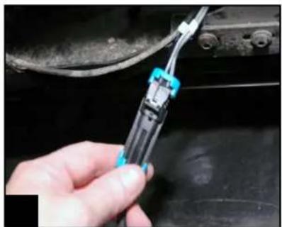
Close-up of a hand using a screwdriver to adjust cable or wire on a black vehicle (no visible text or symbols)Connect the enclosure's wiring pigtail to the connector at the side of the console labeled "Sub 1."
FRONT SPEAKER INSTALLATION
This section covers final installation of the passenger's side front speaker panel and temporary installation of the driver's side speaker panel. Final installation of the driver's side speaker panel occurs after the system is tested and gone through a thorough inspection prior to reassembly.
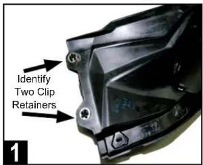
Locate the factory front left and right speaker panels and identify two mounting clip retainers and washers that need to be removed on each.
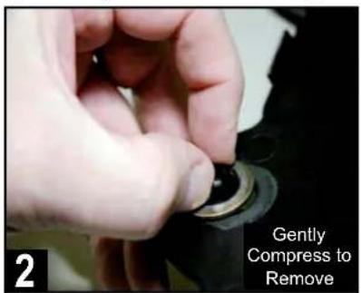
From bottom side, gently remove mounting clip retainers as indicated. This can be done with your fingers. Do this for both passenger and driver side.
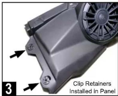
Replace these mounting clip retainers and washers in the same locations of both MB Quart speaker panels in your Can-Am X3 kit. It's a direct fit.

natural_image
Close-up of a hand using a tool to adjust or install electronic components on a mechanical component (no visible text or symbols)Connect passenger side speaker to gray wiring routed earlier to speaker area. Red/black wires are for optional illuminated speaker rings.

natural_image
Person installing or adjusting a black plastic fan on a vehicle chassis (no visible text or symbols)Begin to set passenger side speaker panel in place by loading the edge nearest the center with the clip retainers into position as shown.

natural_image
Close-up of a car hood with blue accents and white arrows pointing to components (no visible text or symbols)Pull center edge of panel up to align clips with the respective dash receiver holes. This is a crucial step to facilitate the correct overall panel fit.
• SOLID GRAY - Right Front Speaker (+)
- GRAY/BLACK - Right Front Speaker (-)

Next, drop the speaker edge of panel into place*. Attach lowest T-30 screw into place to allow check of final panel fit and to ensure all clip holes align.

Secure the front speaker panel by reinstalling all the remaining clips and hardware in the same locations removed during the disassembly process.
\*AFTERMARKET ROLL CAGES
Although MB Quart front speakers come pre-installed in the Can-Am replacement panels, they may require removal from the panel to fit low-slung aftermarket roll cages that fit close to the hood area.
In these cases where fit is tight or would damage the speaker due to the roll cage position, remove the speaker from the panel first, install the panel in the vehicle, then connect and install the speaker into the panel.
FRONT SPEAKER INSTALLATION (Continued)
This section continues front speaker installation focusing on the driver's side.

Remove switches on lower left of original driver's side dash panel by depressing the tabs on the top and bottom of the back of switch.
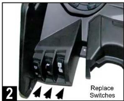
Replace switches in the same locations within the new MB Quart driver's side dash panel by simply pushing each into its mounting opening.

If the vehicle has the Smart-Lok differential control module, attach to the underside of the new dash panel with the original four 8mm screws.
natural_image
Close-up of a metallic mechanical component with mounting holes and a central hub, marked with arrows (no text or symbols visible)Ensure the clip retainers and washers from the original dash panel have been reinstalled correctly before proceeding.

natural_image
Close-up of hands installing or adjusting a mechanical component with visible wiring and components (no text or symbols)Connect driver's side speaker to white speaker wiring near the amplifier harness area. Red/black wires are for optional illuminated speaker rings.
• SOLID WHITE - Left Front Speaker (+)
- WHITE/BLACK - Left Front Speaker (-)
- RED - Illumination + (Optional Grille Required)
- BLACK - Illumination -

natural_image
Close-up of a car's internal components including steering wheel, dashboard, and steering wheel (no visible text or symbols)Set panel temporarily in place without attaching any hardware or clips. Do not yet plug in switches in case amplifier adjustments are needed.
DOUBLE CHECK INSTALLATION STEPS TO THIS POINT
Take a few minutes to double check all of the installation steps to this point ensuring the amplifiers, speakers and wiring has all been connected as shown in these instructions.
PROCEED TO THE NEXT PAGES TO CONFIRM SETTINGS AND BEGIN TESTING THE SYSTEM.
AMPLIFIER SETTINGS
Before source unit and dash reassembly, make (or verify) the following settings the amplifiers. See the INITIAL TESTING and FINE TUNING sections for additional information on final system adjustments and personalized settings. The chart below provides general crossover filter and bass boost switch settings depending on the Can-Am X3 UTV-Tuned Audio package you have.
TUNED PACKAGE TWO-CHANNEL AMPLIFIER MONO AMPLIFIER
| MBQX-STG5-1 HP-OFF-LP/BPSwitch to HP - High Pass (80Hz) | Bass Boost to 0dBLPF at 100Hz |
| MBQX-STG3-1 HP-OFF-LP/BPSwitch to HP - High Pass (80Hz) | Bass Boost to 0dBLPF at 100Hz |
| MBQX-STG2-RAD-1 HP-OFF-LP/BPSwitch to – High Pass (80Hz) | N/A |
| MBQX-STG2-1 HP-OFF-LP/BPSwitch to – High Pass (80Hz) | N/A |
| MBQX-SUB-2 N/A BassBoost to 0dB | LPF at 100Hz |
This manual assumes the full Stage 5 System and provides the information for initial settings accordingly.
STEP 1 - ADJUST TWO-CHANNEL AMPLIFIER
Make the following initial adjustments to the NA2-400.2 shown at right:
• X-OVER - Switch to "HP" position.
- LEVEL - Rotate control to halfway starting at 9V (dial pointing up). This represents an input level that will closely match the source unit's output at full volume allowing the amplifier to achieve full power without notable distortion.
- HP - Rotate control to halfway from 15 Hz (pointing up). This is approximately 80HZ.
- LP - Not used in this application (position does not matter).

STEP 2 - ADJUST MONO AMPLIFIER
Make the following initial adjustments to the NA2-400.1 shown at right:
- BOOST - Switch to "0dB" position.
- LEVEL - Rotate control to 3/4 of the rotation starting at 9v (dial pointing side to side). This represents an input level to match the source unit's output at full volume allowing the full power without notable distortion. Note source unit's "SUB OUT" level setting on next page (35dB) to correlate with this recommendation.

- LPF - Rotate control to 1/4 turn starting at 50 Hz (dial pointing diagonal as shown). This is approximately 100Hz. Note that the source unit's SUB OUT frequency setting on the next page is also set to 100Hz to correlate with this recommendation.
- SUBSONIC - A subsonic filter protects the subwoofer from over excursion. Rotate control to 1/4 turn starting at 15Hz (dial pointing diagonal) as shown. This is approximately 31Hz.
INITIAL TESTING
Confirm that everything is working as intended before final tuning, fitting and reassembly.
STEP 1 - RECONNECT THE BATTERY
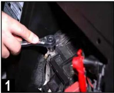
First, ensure the battery is fully charged. Using a 10mm socket, then reconnect the negative terminal of the negative battery cable as indicated.
STEP 2 - CONNECT SOURCE UNIT
Connect the electrical plug and two RCA audio cables to the source unit. The "FRONT" RCA outputs connect to the high frequency (400.2) amplifier. The green "SUB" RCA outputs connect to the subwoofer (400.1) amplifier if add-on sub kit is used. Temporarily set housing in place. Do not yet attach mounting screws. This will allow for any corrections of wiring if needed.
STEP 3 - INSERT MAIN FUSE AT BUS BAR
With the source unit connected, place the 70a MAXI fuse in the fuseholder near the bus bar main harness connection.
STEP 4 - TURN ON IGNITION
Turn the ignition key to the ACC position.
STEP 5 - INITIAL CHECKS
The following instructions are for confirming connectivity and basic functionality. Refer to the full manual for the GMR-LED source unit to use features like Bluetooth® pairing, adjusting treble and bass or working with the EQ. Push the PWR button on the source unit and check the system for all of the following:
- POWER ON - Source unit lights up and responds to button presses.
- USB INPUT (if used) responds when selected.
- AUX 3.5mm INPUT (if used) responds when selected.
- BT MUSIC - Follow the pairing instructions for source unit and test a Bluetooth ^ source.
- AM/FM RADIO - Unless you have installed and AM/FM antenna, you will only hear static.
- SPEAKERS - Confirm all speakers play the correct range of frequencies (lows coming from the subwoofer, mid to high coming from front and rear speakers).
- CORRECT LEFT/RIGHT BALANCE - Make sure you are using the controls on the source unit to confirm "LEFT" is the left-side channel and "RIGHT" is the right-side channel. There will be no change on the fader front/rear speakers as all speakers are on the same two-channel (400.2) amplifier and "FRONT" output.
- SUB FREQUENCY and LEVEL SETTING (if optional subwoofer and amplifier are installed) - In the settings menu, set the source unit's SUB OUT (Low Pass) crossover at 100Hz. Next, set the source unit's SUB OUT level at 35dB for the initial testing. A level setting of 35dB will allow the recommended gain control settings on the subwoofer amplifier to perform distortion-free, while also allowing you to fine tune any bass-heavy music by easily reducing the sub level setting from the source unit.
- AMPLIFIER(S) - If the speakers are playing, the amplifiers are on. Confirm settings are correct if something doesn't sound exactly right. CONFIRM ALL SPEAKERS ARE CONNECTED TO THE CORRECT AMPLIFIER before making any further adjustments. Refer to page 9 and 13 for initial amplifier settings during the amplifier plate installation. If everything is working and producing sound, proceed to the next section - Fine Tuning.
natural_image
Close-up of a hand using a tool to adjust or repair a mechanical component, no visible text or symbols
natural_image
Close-up of a car's engine compartment with visible wiring and components (no text or symbols)
natural_image
Close-up of a hand holding a small electrical plug with black and red wires, no visible text or symbolsFINE TUNING
After you have confirmed and tested that all components are working, you can fine tune the amplifier settings. Through hundreds of installations we have determined the following settings are ideal for the Can-Am X3 UTV-Tuned Audio Packages. Reference source unit volume level for these settings is 30-35 with no boost in bass, treble or EQ settings.
NOTE – Gain control, it is important to adjust each amplifier gain as described in the manual. Remember, these settings are NOT volume controls. Gain controls, properly adjusted help properly balance the system sound between lows, highs and minimize distortion that comes from the source unit. Listen for a clear, crisp audio sound. The ideal gain setting should allow full volume from the source unit without audible distortion.
A Settings
The illustrations below describe the various controls. Refer to the illustration that matches your amplifier.
① GAIN Adjustment
The gain control purpose is to match the output of your source signal to the amplifier. Refer to the section B below for detailed instructions.
② X-OVER Switch
This switch will set the amplifier to have a full frequency output or to filter out high or low frequencies. The NA2-400.2 offers either a low pass (LP) or high pass (HP) filter.
③ Frequencies Adjustment
The Low Pass Filter will cut off the frequencies above the setting. The High Pass Filter will cut off the frequencies below the setting.
④ SUBSONIC Adjustment
The Subsonic Filter will cut off the frequencies below the setting. If using with a subwoofer, the setting should be set between 15-25Hz.
⑤ BOOST Switch

The Boost Switch will increase the signal 12dB at 45Hz. Be aware this setting can cause distortion if the gain is not set properly.
Two Channel Amplifier

Mono (Subwoofer) Amplifier
B Level Setting
This is a critical step to insure your amplifier is properly adjusted to match the signal output level of your source unit.
THIS IS NOT A VOLUME CONTROL!

- If possible, with the source unit off, confirm that the primary volume control is turned down (counter clockwise).
- Turn on the source unit (CD, or MP3 player). Re-confirm that the volume is turned down. Make sure the source unit controls; balance, fader, bass and treble are all set to center or "0" adjustment. Make sure that the green LED on the end of the amplifier is illuminated.
- Play a clean musical selection of which you are very familiar. CD is preferred. Do not use radio signals for level setting. Hit play and start turning the volume of the source unit up.
- Stop increasing the source unit volume when you reach 3/4 (about 75%) or until you hear speakers begin to slightly start producing distortion.
- Increase the amplifier gain (clockwise) until distortion is heard, then back the level down (counter clockwise) until the distortion is eliminated. Small adjustments may need to be made to balance the levels of multiple amplifiers.
VEHICLE REASSEMBLY
As you begin reassembly, take the time to ensure no fastener, screw or clip is excluded. Review any prior disassembly steps to ensure you don't miss any hardware during reassembly.
natural_image
Close-up of a hand adjusting a mechanical component with an arrow pointing to a detail (no visible text or symbols)Plug in all switch wiring on back of the driver side front speaker panel. Test switch functions to ensure they are correctly connected.
natural_image
Interior view of a car cockpit with dashboard and steering wheel (no visible text or symbols)Place driver side speaker panel into its final position*. Check fit so that all open hardware and clip holes are aligned properly.
\*AFTERMARKET ROLL CAGES
Although MB Quart front speakers come pre-installed in the Can-Am replacement panels, they may require removal from the panel to fit low-slung aftermarket roll cages that fit close to the hood area.
In these cases where fit is tight or would damage the speaker due to the roll cage position, remove the speaker from the panel first, install the panel in the vehicle, then connect and install the speaker into the panel.
3 Secure the front speaker panel by reinstalling all the remaining clips and T-30 hardware in the same locations removed during the disassembly process. Do not forget about reinstalling the additional hidden push pin under the driver's side dash, between the steering wheel and console, just forward of the tubular chassis support.
4 Reinstall the gauge panel with the two T-30 screws and two 10mm nuts. With this step completed, the driver side front speaker panel installation should be complete.
5 Follow the main harness from the bus bar and ensure the nuts on the connections are tight. Ensure the harnesses are secured to factory wiring with the included zip ties. Do not zip tie any part of the audio harness or the RCA audio cables to any heat or moisture sources, or to any moving parts.
6 Reinstall lower center console cover with two T-30 screws and two push pins. Refer to the top of page 6 for disassembly steps and simply do these in reverse.
7 Place the source unit's housing in the final center dash installation location with wiring neatly secured and zip tied in place. Attach the four included T-25 Torx screws through the housing's mounting holes into each of the four locations drilled out earlier. Two T-25 32mm screws in the front of the housing and the shorter two T-25 24mm screws in back.
8 Reinstall four T-30 screws in the center dash. Two forward of the gear selector and two additional in the upper center dash forward of the fuse panel. Once complete, reinstall the upper center dash access cover behind source unit housing. Refer to page 4 for disassembly steps and simply do these in reverse.
9 Reinstall driver and passenger center console side panels by gently snapping back into place. Ensure no wiring is exposed or pinched. Refer to page 4 for disassembly steps and simply do these in reverse.
10 Reinstall driver and passenger seats with the original 18mm bolts in the rear and 13mm bolts/nuts in the front. Refer to page 3 for disassembly steps and simply do these in reverse.
FINAL INSPECTION
Here is a check list to make sure your vehicle is ready to hit the trails. You should pull & tighten everything so that you know your Can-Am X3 and your audio equipment are secure.
- BATTERY IS FULLY CHARGED, ESPECIALLY AFTER TESTING AND FINE TUNING
- NEGATIVE BATTERY TERMINAL IS TIGHT AND SECURE
• NUTS WERE TIGHT ON HARNESS CONNECTION AT THE BUS BAR IN CENTER CONSOLE - ALL POWER/SPEAKER HARNESSES IN CENTER CONSOLE ARE SECURED SO NOTHING IS LOOSE
- AMPLIFIER(S) MOUNTED AND ALL 7 NUTS WERE SECURED TO DUAL AMPLIFIER PLATE (3 NUTS IF ONLY THE 400.2 AMPLIFIER IS USED)
- RIGHT FRONT SPEAKER PANEL FINAL MOUNTING FITS PROPERLY
- LEFT FRONT SPEAKER PANEL FINAL MOUNTING FITS PROPERLY
- ALL CENTER DASH AND CENTER CONSOLE PANELS ARE SECURED AND FITTED PROPERLY
- SUBWOOFER MOUNTS UNDER FRONT SEAT(S) ARE SECURE WITH SEATS REINSTALLED - IF ADD-ON SUBWOOFER KIT WAS INSTALLED
- ALL SEATS MOVE PROPERLY FORWARD AND BACKWARD
- ENSURE NO LEFTOVER ORIGINAL HARDWARE - EVERY CLIP, SCREW & FASTENER IS IN PLACE
- ACCOUNT FOR ALL YOUR TOOLS SO NOTHING IS MISSING
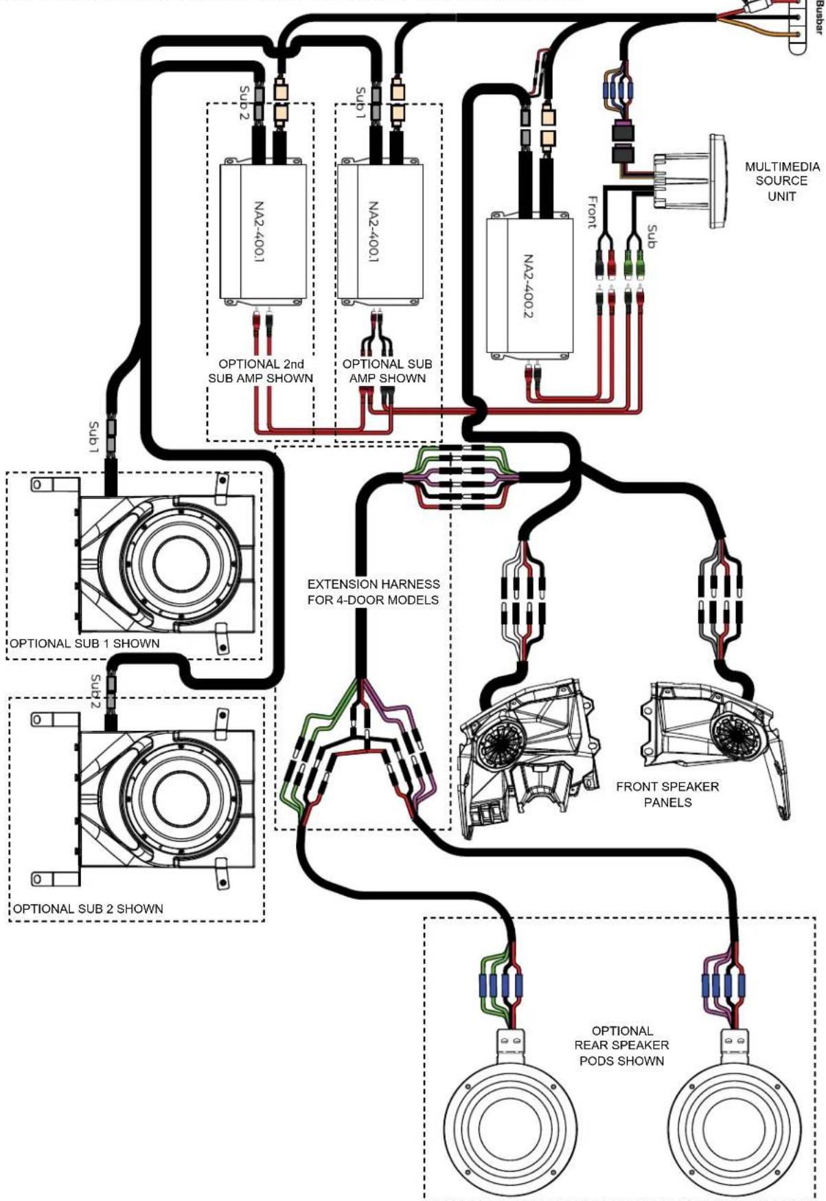
COMPLETE WIRING LAYOUT
This is a complete wiring harness layout diagram, including optional equipment.
BUS BAR (CENTER CONSOLE)
NOTES
Use this section to record serial numbers of each product, final gain and crossover settings of amplifiers or any other wiring or installation-related details that will be helpful if you need to add on to the system or troubleshoot any unforeseen issues.


MBQuart.com #MUSIC DEFINED
FCC Notice
This equipment has been tested and found to comply with the limits for a Class B digital device, pursuant to part 15 of the FCC Rules. These limits are designed to provide reasonable protection against harmful interference in a mobile installation. This equipment generates, uses and can radiate radio frequency energy and, if not installed and used in accordance with the instructions, may cause harmful interference to radio communications. However, there is no guarantee that interference will not occur in a particular installation.
WARNING: Changes or modifications not expressly approved by the party responsible for compliance could void the user's authority to operate the equipment.
This equipment complied with FCC radiation exposure limits set forth for an uncontrolled environment. This equipment should be installed and operated with minimum distance 20cm between the radiator & your body.
WARRANTY
Maxxsonics USA Inc. warrants this product, to the original consumer purchaser, to be free from defects in material and workmanship for a period of one (1) year from the date of purchase. Maxxsonics USA Inc. will, at its discretion, repair or replace defective products during the warranty period. Components that prove to be defective in materials and workmanship under proper installation and use must be returned to the original authorized Maxxsonics USA Inc. retailer from where it was purchased. A photocopy of the original receipt must accompany the product being returned. The costs associated with removal, re-installation and freight are not the responsibility of Maxxsonics USA Inc. This warranty is limited to defective parts and specifically excludes any incidental or consequential damages connected therewith. To view the full warranty, please visit the website.
The Bluetooth ^® word mark and logos are registered trademarks owned by the Bluetooth SIG, Inc. and any use such marks by MB Quart is under license.
All product names, logos, and brands are property of their respective owners. All company, product and service names used in this literature are for identification purposes only. Use of these names, logos, and brands does not imply endorsement.
MBQuart products are designed and engineered in the USA by

MAXXSONICS®
www.maxxsonics.com
MBQUARTI® MUSIC. DEFINED.
GMR-LED
AM/FM/USB/Bluetooth®
Multimedia Controller
for Off-Road and Marine

Operator's Guide and Installation Instructions
Congratulations for choosing the AM/FM/USB Bluetooth Multimedia Controller by MB Quart. For more detailed information about the product, please visit MBQuart.com

CAUTION

Always consider consulting a professional audio installation technician before installing any mobile audio components. Be careful and take your time. Do not let wires make contact with metal edges, sources of moisture or hot engine components.
General Information
Powersports and Marine Multimedia Source Unit
AM/FM, Weather Band Radio, USB, Bluetooth® and AUX sources 160 Watts Peak Power with Pre Amplifier Line Outputs Marine Certified to IPX67 for Water and Dust Intrusion
Auxiliary A/V Sources
Quick Connect Bluetooth Audio USB Audio Input w/Charging Auxiliary RCA Stereo Preamp Input Weather Band Radio Composite Video Camera Input Composite Video Output
AM / FM / Weather band Section
USA Frequency: FM87.9 – 107.9MHz / AM530-1710kHz Europe Frequency: FM87.5 – 108MHz / AM522 – 1620kHz NOAA NWR Weather Band Frequency: 162.400-162.550MHz Intermediate AM/FM Frequency: 10.7MHz Intermediate Frequency Rejection: 50dB Noise Limit Sensitivity: >5uV
USB / AUX / Bluetooth Audio Section
RCA S/N: >81dB Powered Outputs S/N: >74dB USB A/D Conversion: 16bit Frequency Response: 20Hz – 20KHz
Audio Section & Other Features
Power Output: 4 x 40 Watts Max (160 Watts Peak Power) Load Impedance: 4 - 8 Ohms / Channel Preamp Output Voltage: 4 volts Dual Zone Capability between Preamp Outputs and Built-in Power Independent Subwoofer Level Control with Selectable Low Pass Filter 8-Band Graphic EQ (62, 125, 250, 500, 1K, 4K, 10K and 16K)
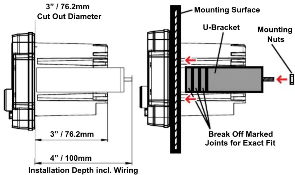
Installation Specifications
4" / 100mm - Total Mounting Depth Required (Incl. U-Bracket) 3" / 76.2mm - Cut Out Diameter
Water Tight Plug Face Shown (Wires to Connect Exit Rear)

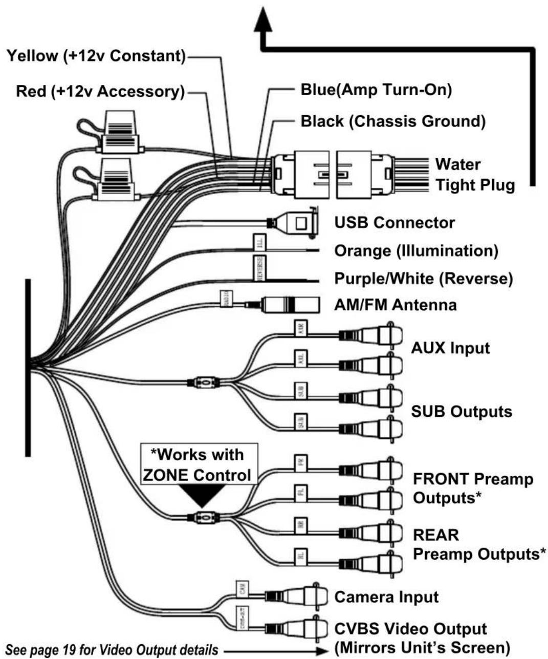
flowchart
graph TD
    A["Yellow (+12v Constant)"] --> B["Red (+12v Accessory)"]
    C["Blue(Amp Turn-On)"] --> D["Black (Chassis Ground)"]
    E["Water Tight Plug"] --> F["USB Connector"]
    G["Orange (Illumination)"] --> H["Purple/White (Reverse)"]
    I["AM/FM Antenna"] --> J["AUX Input"]
    K["AUX Inputs"] --> L["SUB Outputs"]
    M["FRONT Preamp Outputs*"] --> N["REAR Preamp Outputs*"]
    O["Camera Input"] --> P["CVBS Video Output (Mirrors Unit's Screen)"]
    Q["*Works with ZONE Control"] --> R["Sub Inputs"]
    S["See page 19 for Video Output details"] --> T["Sub Inputs"]
    U["Sub Inputs"] --> V["Sub Outputs"]
    W["Sub Outputs"] --> X["FRONT Preamp Outputs*"]
    Y["Sub Outputs"] --> Z["REAR Preamp Outputs*"]
Note: See wiring chart on next page for connection tips, wire colors and functions. Also note preamp level output connections if using external amplifiers and ZONE control capability.
Wiring and Connections
- We recommend wire-to-wire connections such as power, ground and speaker wiring are soldered and protected with either heat shrink tubing or high quality electrical tape.
- The main (yellow) power wire should be connected to a source with at least 10 amps of additional current capability to support the unit.
| Wire Color Location Function | ||
| Black Plug Pin A | Negative Chassis Ground (-) | |
| Blue Plug Pin B | Amp Turn-On (+12v Output) | |
| Green Plug Pin C | Left Rear Speaker (+) | |
| Green/Black Plug Pin D | Left Rear Speaker (-) | |
| Gray/Black Plug Pin E | Right Front Speaker (+) | |
| Gray Plug Pin F | Right Front Speaker (-) | |
| Purple Plug Pin G | Right Rear Speaker (+) | |
| Purple/Black Plug Pin H | Right Rear Speaker (-) | |
| Red Plug Pin J | +12 volt Accessory | |
| White Plug Pin K | Left Front Speaker (+) | |
| White/Black Plug Pin L | Left Front Speaker (-) | |
| Yellow | Plug Pin M | +12 volt Constant (>10a) |
| Purple/White | Harness | Reverse Camera +12v Input |
| Orange | Harness | +12 volt Illumination |
Preamp Level Audio Connections
- Front and rear RCA preamp outputs are labeled as such. These are intended to be connected to external amplifiers, not included.
- Subwoofer RCA outputs (green RCAs) are mono and paralleled. They are identical subwoofer audio signals. Their frequency range is controlled by the low pass crossover and the subwoofer level control. Both are found in SETTINGS. See Page 18. We recommend starting with 100Hz for the low pass crossover point.
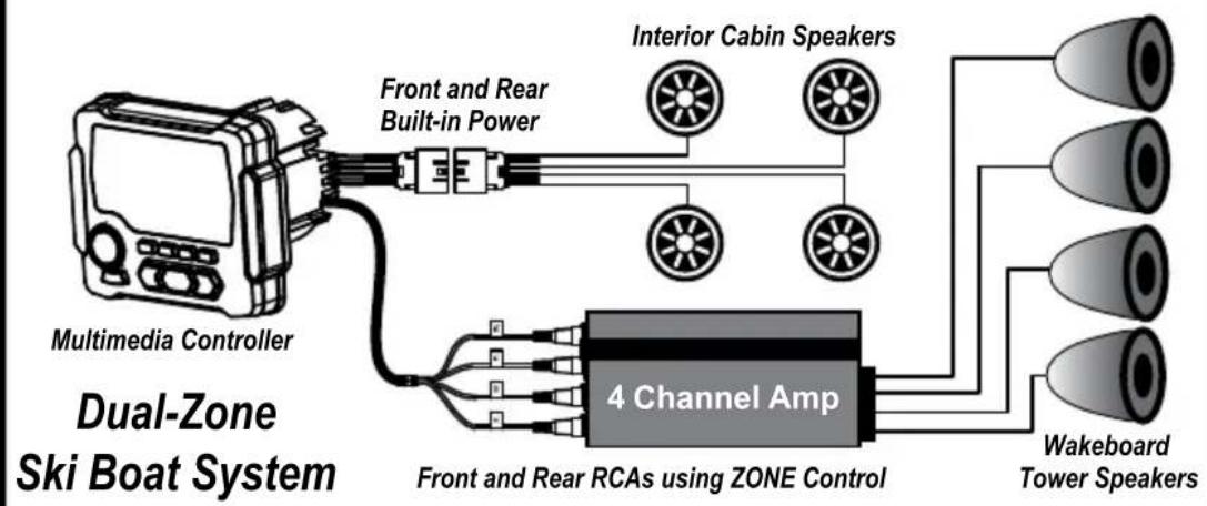
- The unit offers a zone control feature to balance sound levels between different zones. The front and/or rear RCA outputs (using external amplifiers) are one zone. The source unit's built-in power is the other zone. An example is a boat having separate volume control of amplified wakeboard tower speakers versus cabin speakers positioned closer to listeners using the unit's built-in power. Zone level control is found in SETTINGS. See page 18. Subwoofer RCA outputs or speaker-level outputs are unaffected by the zone level control. All work with the main volume.
Rear Mounting Instructions
- Check for appropriate mounting depth and mechanical or electrical obstacles behind the mounting panel BEFORE any cutting. Including the “U”-shaped aluminum mounting bracket, at least 4” (100mm) depth is required.
- Using a 3" hole saw or air saw, cut a 3" (76.2mm) diameter hole in the mounting panel. Use a file or sandpaper to smooth out any rough edges after the cut is complete.
- Thread the two supplied bolts into the back of the multimedia controller using a 9/32" nut driver or deep socket. The threaded holes are located just above the wiring harness in the heatsink.
- Thread two of the supplied 9/32" mounting nuts upside down on the bolts. The flat surface of the nut will sit flush with the inside of the mounting bracket to allow spacing (if needed).
- Insert the source unit through the mounting hole opening. Be sure to allow enough depth for wiring to be securely tied up once the installation is complete.
- Attach the aluminum mounting bracket to gauge the sizing and that it will fit over the supplied threaded bolts. If necessary, use pliers to break away the marked sections until the bracket fits snugly against the mounting panel. Be sure the bracket clears the wiring on the back of the unit without rubbing or heavily bending the wires.
- Attach the remaining supplied 9/32" mounting nuts on the threaded bolts to secure the mounting bracket.
Installation Opening & Depths Mounting Bracket Details
Front Mounting Instructions
- Check for appropriate mounting depth and mechanical or electrical obstacles behind the mounting panel BEFORE any cutting. At least 3.75" (95.25mm) depth is required.
- Using a 3" hole saw or air saw, cut a 3" (76.2mm) diameter hole in the mounting panel. Use a file or sandpaper to smooth out any rough edges after the cut is complete.
- Remove the snap-in covers on the front panel hiding the mounting holes. Use a small flat head screw driver in the two small indents on each cover to gently pry open.
- Insert the source unit through the mounting hole opening. Be sure to allow enough depth for wiring to be securely tied up once the installation is complete. Ensure the source unit is level.
- Mark four (4) holes using an awl, straight pick tool or 1/16" (1.5mm) drill bit to make the markings. DO NOT DRILL THROUGH WITH THE SOURCE UNIT IN PLACE.
- Remove the source unit and gently drill the four (4) marked locations for mounting holes using a drill with a 1/16" (1.5mm) drill bit.
- Re-insert the source unit in the opening. Gently install the four supplied screws in each of the mounting holes with a handheld screwdriver. Do not use drills or battery-powered screw guns for this step.
- Replace the snap-in covers on the source unit's front panel.
Installation Opening & Depths Front Mounting Details
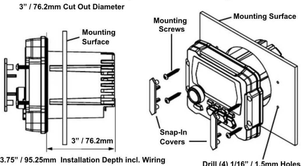
Drill (4) 1/16" / 1.5mm Holes
Front Panel Controls
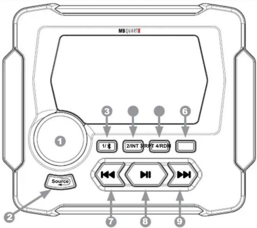
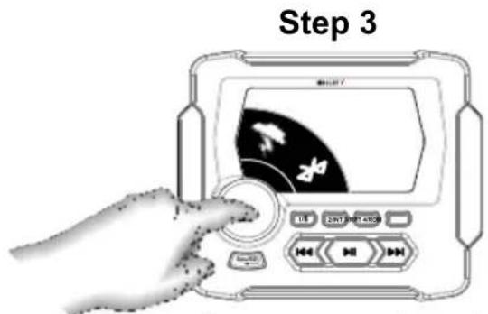
1 POWER/Selector and Volume Knob
- Press the POWER/Selector Knob to power on the unit.
- Rotate the POWER/Selector Knob to view sources when source selection menu wheel is displayed. To select a source, press and release the POWER/Selector Knob.
- Rotate the POWER/Selector and Volume Knob to increase or decrease sound levels once a source is selected.
- Press and hold the POWER/Selector Knob for 5 seconds to power the unit off.
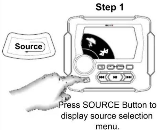
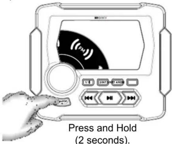
2 SOURCE Button
- Press the SOURCE button to display the source selection menu wheel. See next page for details. Also functions as the "back" button in a SETTINGS menu (such as EQ, Audio, Zone Volume, Clock Adjust, Backlight, etc.)
3 1/ ✱ Button
- Preset 1 for AM/FM, pairing on Bluetooth source.
4 2/INT Button
- Preset 2 for AM/FM. No other function.
5 3/RPT Button
- Preset 3 for AM/FM. Repeat play (1 or all) on USB source.
6 4/RDM Button
- Preset 4 for AM/FM. Random play (Shuffle) on USB source
7 Scan Down for AM/FM or Track Back for USB/Bluetooth source.
8 Mute for AM/FM and AUX or Play/Pause for USB/Bluetooth source.
9 Scan Up for AM/FM or Track Up for USB/Bluetooth source.
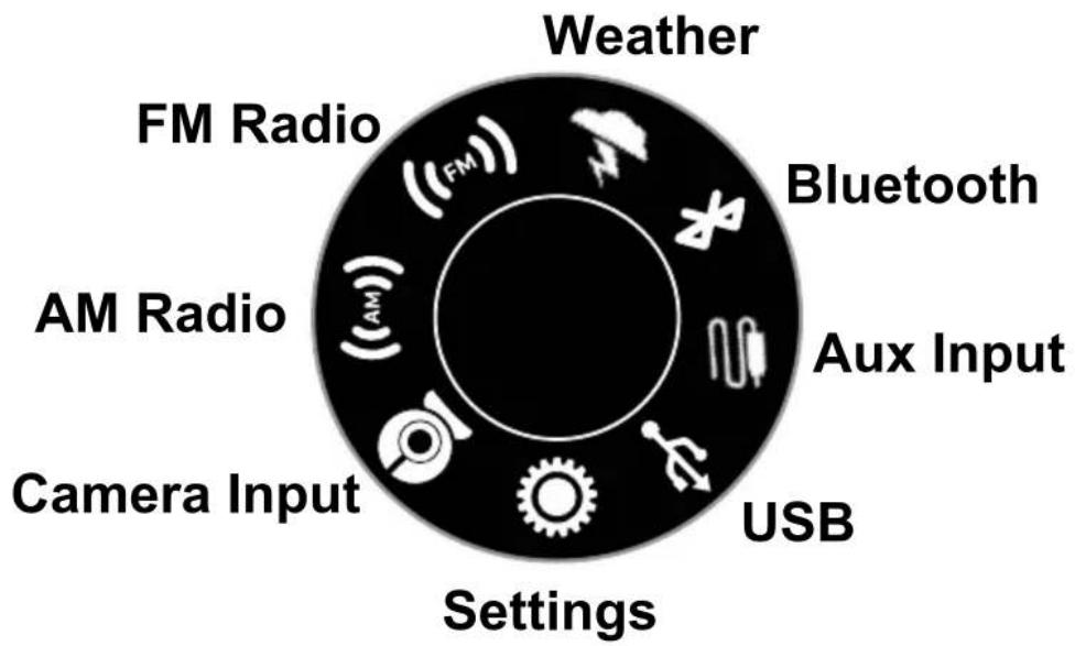

Press Selector Knob (once) to complete source selection menu.
Note: On USB source, the unit "auto selects" USB input whenever a device is plugged in. All other sources must be selected by the user. When selecting Bluetooth, a device must be first paired to playback audio.
AM/FM Configuration
Several configurable AM/FM radio parameters are available.
- Select between AM or FM on the Source Menu wheel. Each has its own menu.
- Once the chosen source is selected, press and hold the SOURCE button for 2 seconds. The AM or FM menu will appear (whichever source is selected).
- Use the source menu selector knob to scroll to the chosen parameter. Press the center of the knob to either adjust the parameter directly, or enter the sub-menu and adjust by scrolling and pressing the center of the knob again.
- A complete list of each parameter and its variables is listed on the following page.
After selecting AM or FM source, press and hold SOURCE button for 2 seconds to enter the AM or FM Settings menu. Use the Menu Selector Knob to navigate the menu items.

- Use the SOURCE button to go back to the previous screen.
- Continue using the SOURCE button to exit AM or FM setup.
Settings Choices for AM
- PRESETS - This function shows stored AM presets 1-6 on AM1 or AM2. Only presets 1-4 have front panel quick access buttons without using this menu.
- SAVE PRESETS - This function stores AM presets in spaces 1-6. Only presets 1-4 have front panel quick access buttons.
- RADIO REGION - This function specifies the region: EUROPE, USA1, USA 2, JAPAN or RUSSIA. This function also controls FM RADIO REGION setting simultaneously and will reset the clock. USA1 is recommended for USA.
- LOCAL - This function filters out weaker signals when ON to limit only strong stations in seek feature. Choose OFF when signals have with adequate reception. Also controls FM LOCAL setting.
- AM BAND - This function selects AM1 or AM2 bands. Choose and store and recall AM presets. 6 on AM1, 6 on AM2.
- AUTO STORE - Automatically searches and stores presets in memory.
- STEREO - Choose STEREO or MONO. Recommended to set to MONO for AM as AM radio signal is broadcast in mono.
Settings Choices for FM
- PRESETS - This function shows stored FM presets 1-6 on FM1, FM2 or FM3. Only presets 1-4 have front panel quick access buttons without using this menu.
- SAVE PRESETS - This function stores FM presets in spaces 1-6. Only presets 1-4 have front panel quick access buttons.
- RADIO REGION - This function specifies the region: EUROPE, USA1, USA 2, JAPAN or RUSSIA. This function also controls AM RADIO REGION setting simultaneously and will reset the clock. USA1 is recommended for USA.
- LOCAL - This function filters out weaker signals when ON to limit only strong stations in seek feature. Also controls AM LOCAL setting.
- FM BAND - This function selects between FM1, FM2 or FM3 bands. Choose and store and recall FM presets. 6 each on FM1, FM2 & FM3.
- AUTO STORE - Automatically searches and stores presets in memory.
- STEREO - Choose STEREO or MONO. Recommended to set to STEREO for FM as FM radio signal is broadcast in stereo.
Once setup is complete, select between AM or FM icons on the Source Menu wheel or simply press the SOURCE button to back up to the source screen showing the current AM or FM frequency.
- Press the ◀◀◀ or ▶▶buttons less than 1 second to manually seek radio stations one frequency at a time.
- Press the ◀◀◀ or ▶▶buttons more than 1 second to automatically seek the next / previous radio stations with strong reception.
- Press and hold buttons 1-4 below the screen to store a preset. Four AM and four FM preset locations are available on the front panel.
Note: Two more AM and FM presets (5 and 6) are located in the AM and FM setup menus, but note that 5 and 6 are only accessible through the menu, not the front panel buttons.
- Press the center ▶■ button to mute the AM or FM source. Press ▶■ again to unmute or simply rotate the volume control knob.


FM Screen Example AM Screen Example
Weather Band Operation
Select the Weather icon on the Source Menu wheel.
- Press the ◀◀◀ or ▶buttons less than 1 second to manually seek weather band stations one frequency step at a time.
- Press the ◀◀◀ or ▶▶buttons more than 1 second to automatically seek the next / previous weather band stations with strong reception.
- Press the center ▶|| button to mute the weather band source. Press ▶|| again to unmute or simply rotate the volume control knob.
- Press and hold buttons 1-4 below the screen to store a preset. Four weather band preset locations are available.

Weather Band Screen Example
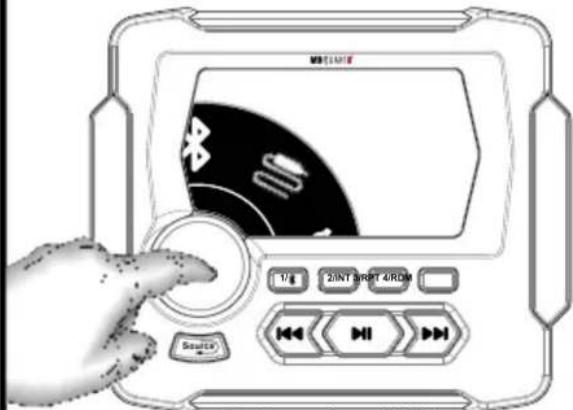
Bluetooth Pairing
The multimedia controller supports Bluetooth A2DP for wireless music streaming from a mobile device, such as a smartphone or streaming music source component. The unit does not support the HF (Hands-Free) or PBAP (Phone Book Access for Contacts) profiles. No calling features are available, only Bluetooth music streaming.
Pairing a Bluetooth device:
- Ensure the multimedia controller is on and Bluetooth is the selected source. The screen will show "BT Disconnected!"

BT Disconnected Screen
- Ensure the Bluetooth functionality on the mobile device is enabled and supports A2DP audio streaming.
- Scan for "MB QUART" in the Bluetooth list on the mobile device.
- Select "MB QUART" and the connection will then be made automatically.
- A "BLUETOOTH Loading" screen will appear briefly as the mobile device's song info and album art are transferred to the multimedia source unit.
Included in Bluetooth Play Screen:
Album Art (or Music Note Icon)
Song Title and Artist Info
Time Elapsed in Song Play
Play or Pause Status

BT Connected Screen
See next page if a pin code is required to pair.
If a PIN Code is Required:
- Some Bluetooth devices require inputting a pass code for connection. Please input code "0000" and the connection will be made automatically.
Automatically Connecting:
- Once the multimedia controller has made a connection with the Bluetooth mobile device for the first time, the unit can then connect to the Bluetooth mobile device automatically within a valid range.
Manually Disconnecting:
- To disconnect temporarily, for example to take a phone call, press and hold the 1 button for 3 seconds and the mobile device will disconnect. If no phone call is in progress, it will automatically reconnect to the unit in about 15 seconds.
- To disconnect and allow another user to connect, use the mobile device to forget the "MB QUART" connection entirely.
Once a Bluetooth device is paired and recognized:
- Be sure the multimedia controller has the Bluetooth source selected. The multimedia controller should automatically begin playing where the mobile device last left off of the music player's song or playlist.
- If the unit does not automatically begin playing, press the center ▶■ button to play the Bluetooth source. The play (▶) symbol will display when music is playing. The time elapsed in the song play is also displayed on the screen.
- Press ▶■ again to mute and pause the song. The pause (I) symbol will display when music is paused.
- Press ▶II again to resume playback or simply rotate the volume control knob.
- Press the ◀◀◀ or ▶buttons more than 1 second to manually fast forward or rewind within a song. Press the same button again to stop the fast forward or rewind function.
- Press the ◀◀◀ or ▶buttons less than 1 second to automatically fast forward or rewind the next / previous song.
Note: Functions such as "Repeat" and "Random Play" (a.k.a "Shuffle") must be controlled at the mobile device directly.
See the USB Input section for smartphones connected via USB and the capability for Repeat and Random (Shuffle) functionality.
The multimedia controller supports MP3, WMA, and WAV audio files with a USB thumb drive connected. Additionally, M4A or Apple Lossless file types are supported if the user connects an iPhone® using iTunes as the music player.
Most smartphones with a USB-based charging connector and USB thumb drives easily connect to the multimedia controller. Many smartphones include album art through the phone's music player. Some USB thumb drive files may not include album art, only song information.

To begin, connect a USB device and the unit reads the music files automatically.
- A "USB Loading" screen appears as the device's song info and album art (if present) transfer to the unit. Smartphones take a few seconds longer than a USB thumb drive.
- If the unit does not automatically begin playing, press the center ▶|| button to play the USB source. Press ▶|| again to mute and pause the song. Press ▶|| again to resume playback or simply rotate the volume control knob.
- Press the ◀◀◀ or ▶▶buttons more than 1 second to manually fast forward or rewind within a song. Press the same button again to stop the fast forward or rewind function.
- Press the ◄◀◀ or ▶▶buttons less than 1 second to automatically fast forward or rewind the next / previous song.
Read about Repeat (RPT) and Random (RDM) modes and controls on the following page. Smartphones behave differently than USB drives.
USB Thumb Drive Screen:
Album Art (or Music Note Icon)
Song Title and Artist Info
Time Elapsed in Song Play
Play or Pause Status
Status of RPT (even when OFF)
Status of RDM (only when ON)

USB Thumb Drive Screen
USB Smartphone Screen:
Album Art (or Music Note Icon)
Song Title and Artist Info
Time Elapsed in Song Play
Play or Pause Status
Status of RPT & RDM (only when ON)

USB Smartphone Screen
USB RPT and RDM Functionality
The multimedia controller has two modes of making a USB-connected music library more interesting with Repeat (RPT) and Random (RDM) functions. Random play is also called "Shuffle" on some mobile devices.
USB Thumb Drive RPT and RDM
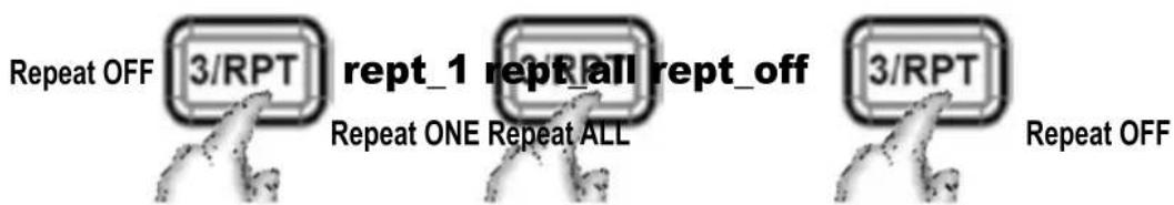
With a thumb drive connected to the USB input, users see an icon on the right side of the screen (centered) that indicates the status of the RPT mode. The default status is off. RDM (Shuffle) default status is off and no icon shows until it is engaged.

natural_image
Abstract black-and-white graphic of a stylized loop or chain link (no text or symbols)Repeat OFF
- The RPT sequence of button presses is as follows:

flowchart
graph LR
    A["Start"] --> B["3/RPT"]
    B --> C["Reset"]
    C --> D["3/RPT"]
    D --> E["Reset"]
    E --> F["3/RPT"]
    F --> G["End"]
- The RDM (Shuffle) sequence of button presses is as follows:

USB Smartphone RPT and RDM
With a smartphone connected to the USB input, users see no icons. When a function is active, the screen displays a text message of the mode above 3/RPT button. The default status of RPT and RDM (Shuffle) are both off.
- The RPT sequence of button presses is as follows:
- The RDM (Shuffle) sequence of button presses is as follows:

Auxiliary (AUX) Input and Camera
The multimedia controller has right and left preamp level RCA connections for the Auxiliary Input. If a portable device with a headphone jack is used, a 3.5mm (male) to RCA (male) adapter cable is required and not included.
Select the AUX icon on the Source Menu wheel.
- Press play on the auxiliary device and turn up its volume. Volume is controlled from the Selector/Volume Knob on the unit.
- Press the center ▶|| to mute. This only mutes the input. It does not pause the song. Press ▶|| again to unmute or simply rotate the volume control knob.
Select the AUX icon in the menu.

After selecting AUX in the source menu, begin paying the music on the auxiliary device. Turn its volume up. Main volume can then be controlled via the unit along with muting audio.
Camera Operation
- Connect the yellow RCA "Camera Input" to the installed camera's composite video output.
- Connect the camera per the camera manufacturers recommendations
- Connect a +12 volt trigger, typically a reverse gear signal, to the unit's purple/white wire. This automatically triggers the camera screen when active. It should supply +12 volts to trigger.
- User can also manually select the "Camera" source from the menu.

Manually select the Camera icon or trigger automatically w/reverse input.
natural_image
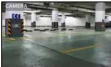
Interior view of a modern parking garage with visible signage and parking areas (no readable text or symbols)The unit displays a clear picture of whatever view the camera views. This could be used for a front thermal imaging UTV camera or boat docking camera depending on the application.
SETTINGS Menu
To access SETTINGS, press Selector/Volume knob in any source. The "SETTINGS" menu appears immediately. Alternatively, select "SOURCE" and navigate to the SETTINGS icon ("Gear" icon), then press the Selector/Volume knob to access the menu.
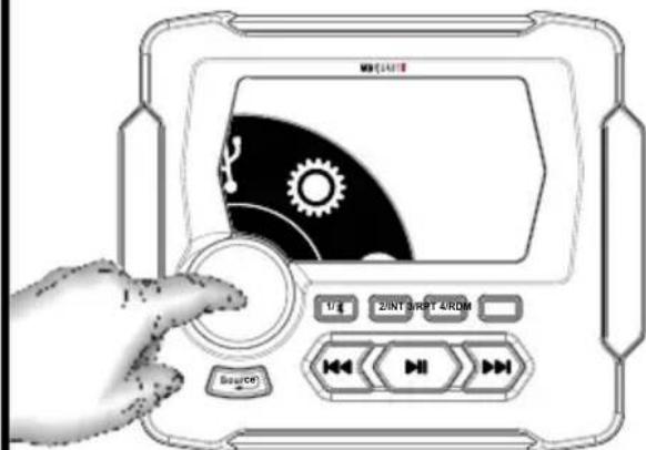
Press the Selector/Volume knob in any source, or select the "Gear" icon.
Use the Selector/Volume knob to navigate the main menu by turning to scroll and pressing to enter a specific feature or sub-menu.
- Use the Selector/Volume knob to navigate the menu items. When the gray highlighted bar is on the chosen parameter, press the Selector/Volume knob to go into that menu (or sub-menu). This is similar to an "Enter" command. Use the Selector/Volume knob to navigate parameters within the menu. Once the parameter is set, use the SOURCE button to go back to the previous screen.
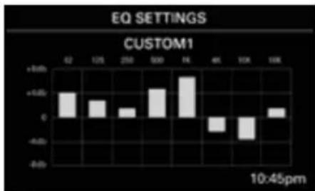
Equalization (EQ)
- Use the Selector/Volume knob to select the 8-band graphic EQ.
- Navigate each EQ band by turning the knob and select the band by pushing the knob.
- Adjust each band as desired, then push the knob again to move to another band.
- Use the SOURCE button to close the EQ screen when complete and return to the main menu.
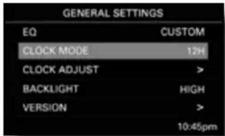
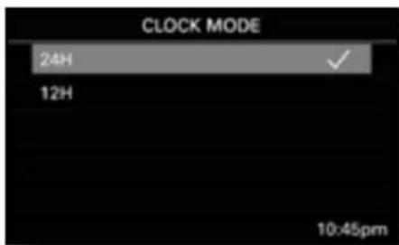
Clock Mode
- Access the clock mode menu to adjust 12 hour (USA) and 24 hour (Europe/World) clock.
- Verify preferred setting with the check marked choice.
- Use the SOURCE button to close the clock mode screen when complete and return to the main menu.
bar
EQ SETTINGS CUSTOM1 | Time | Value | | :--- | :--- | | 62 | +3.0 | | 125 | +2.0 | | 250 | +1.0 | | 500 | +4.0 | | 76 | +8.0 | | 41 | -3.0 | | 10K | -5.0 | | 14K | +1.0 | 10:45pm8 EQ Bands: 62Hz, 125Hz, 250Hz, 500Hz, 1KHz, 4KHz, 10KHz and 16KHz
SETTINGS Menu (Continued)
Clock Adjust
- Access the clock adjust mode menu to change the time displayed on the unit's main screen.
- Navigate each time parameter (hour, then minute) by turning the knob and select by pushing the knob.
- Adjust the hour parameter as desired, then push the knob again to move to minutes.
- AM or PM settings are automatically determined by the clock mode settings (12 or 24 hour format).
- Use the SOURCE button to close the clock adjust screen when complete and return to the main menu.

Clock Adjust Screen
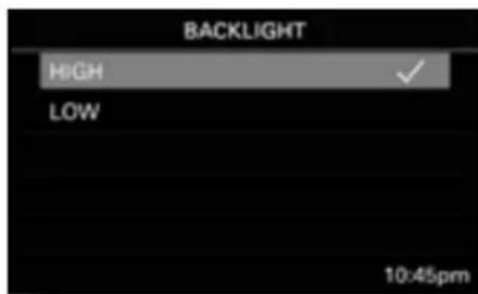
Backlight
- Access the backlight menu to adjust the brightness of the screen lighting.
- Verify preferred setting with the check marked choice.
- Use the SOURCE button to close the backlight screen when complete and return to the main menu.
Backlight Adjust Screen
Version
- This menu reports the software version in the unit. No settings or changes are available to the user.
AUDIO Settings Sub-Menu
Access the "Audio" menu and the following adjustments are available:
SUB Frequency
- Adjust the low pass crossover for the SUB preamp (green) RCA outputs. The choices are 80Hz, 100Hz and 120Hz.
SUB Level
- Adjust the relative volume level for the SUB preamp (green) RCA outputs in a range of 0 (fully attenuated) to 40 (fully open).
ZONE Level
- Adjust the relative volume level for the front/rear preamp RCA outputs in a range of 0 (fully attenuated) to 40 (fully open). The unit's built-in power and SUB levels are unaffected by this adjustment. Only the front/rear preamp outputs are controlled by the zone volume. See page 20-21 for example system diagrams utilizing zone control.
BASS Level
- Adjust the bass from -7 to +7. Default setting is "0." Center frequency is 100Hz.
TREBLE Level
- Adjust the treble range from -7 to +7. Default setting is "0." Center frequency is 10KHz.
BALANCE Control
- Adjust the balance between the left and right speakers using the grid on the screen and the Selector/Volume knob to move the dot. Equal balance (center dot) is the default setting.
- Use the SOURCE button to close the balance screen when complete and return to the main menu.
FADER Control
- Adjust the fader between the front and rear speakers using the grid on the screen and the Selector/Volume knob to move the dot. Equal fader position between front/rear (center dot) is the default setting.
- Use the SOURCE button to close the fader screen when complete and return to the main menu.
Although the balance and fader adjustments are two separate screens, for purposes of easy understanding they are shown here in the same screen. Left and right of the grid represent the balance. Top (front) and bottom (rear) of the grid represent the fader.

Factory Reset
- This setting resets the unit to its factory defaults. Be cautious when entering this menu if you don't want to manually reset all your preferences such as radio presets, EQ, sub level/crossover, backlighting, etc.
Video Output Feature
- The multimedia controller features a composite video output that mirrors the same information on the unit's screen. This is a useful feature to provide a secondary screen for passengers or in other zones within a larger space, such as a boat or RV.
- Simply connect the unit's "CVBS-OUT" to the composite video input of a secondary screen.

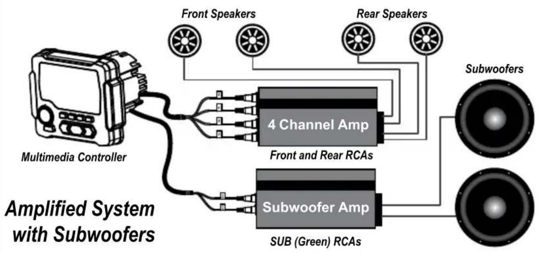
Audio System Design Ideas
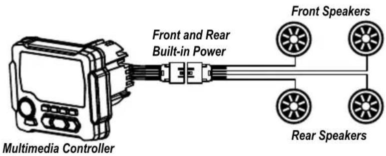
4-Speaker System using Built-in Power
flowchart
graph TD
    A["Multimedia Controller"] --> B["4 Channel Amp"]
    A --> C["Subwoofer Amp"]
    B --> D["Front and Rear RCAs"]
    C --> E["Sub (Green) RCAs"]
    D --> F["Rear Speakers"]
    E --> G["Subwoofers"]
    style A fill:#f9f,stroke:#333
    style B fill:#ccf,stroke:#333
    style C fill:#ccf,stroke:#333
    style D fill:#cfc,stroke:#333
    style E fill:#cfc,stroke:#333
    style F fill:#fcc,stroke:#333
    style G fill:#fcc,stroke:#333
flowchart
graph TD
    A["Multimedia Controller"] -->|Front and Rear Built-in Power| B["4 Channel Amp"]
    B --> C["Interior Cabin Speakers"]
    B --> D["Wakeboard Tower Speakers"]
    B --> E["Front and Rear RCAs using ZONE Control"]
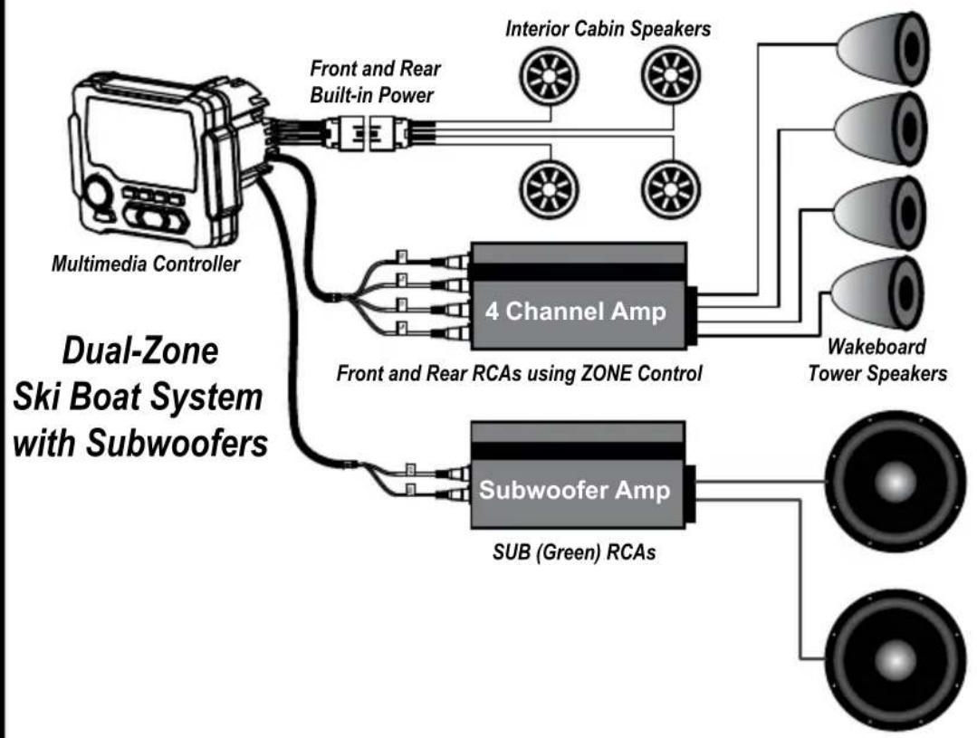
flowchart
graph TD
    A["Multimedia Controller"] --> B["Front and Rear Built-in Power"]
    B --> C["Interior Cabin Speakers"]
    C --> D["4 Channel Amp"]
    D --> E["Wakeboard Tower Speakers"]
    D --> F["Subwoofer Amp"]
    F --> G["SUB (Green) RCAs"]
    G --> H["Speaker"]
    style A fill:#f9f,stroke:#333
    style B fill:#ccf,stroke:#333
    style C fill:#cfc,stroke:#333
    style D fill:#fcc,stroke:#333
    style E fill:#cff,stroke:#333
    style F fill:#ffc,stroke:#333
    style G fill:#cfc,stroke:#333
    style H fill:#fcc,stroke:#333
Problem Cause Solution
| No power(Unit does not turn on) | 1. Incorrect wiring2. Fuse is blown3. Wiring harness is not connected | 1. Re-check wiring2. Replace fuse3. Re-check wiring harness connection |
| No sound(Only with built-in power used) | 1. Volume is too low2. Speaker wire connection loose or wired incorrectly | 1. Increase volume2. Double check connection and re-attach |
| No sound(Only on external amplifiers) | 1. Amplifiers not connected to power2. Amplifiers not turning on | 1. Check amplifier power/ground connections2. Connect blue remote turn on wire |
| No AM/FM reception | 1. Antenna cable is not connected2. The signals are too weak | 1. Insert the antenna cable securely2. Select a station manually |
| AUX Input or RCA output distortion | 1. Volume may be up too much on external device | 1. Lower volume on external device until distortion goes away |
| External amplifiers have low signal input. Gain too high (hiss) | 1. Zone control is turned down too far | 1. Increase zone control level to provide more signal level to amplifiers |
| Bluetooth can't/won't connect | 1. Mobile device has BT switched off2. Mobile device is not discoverable | 1. Enable the Bluetooth function2. Make the device discoverable |
| USB thumb drive not reading | 1. Music file is not MP3, WAV or WMA format | 1. Convert music file format into MP3, WAV or WMA format |
| Camera does not display in reverse, only in camera source menu | 1. Purple/white reverse trigger wire not powered | 1. Power the purple/ white wire on the back of the unit with +12v trigger |
If you have problem or question that was not mentioned here, please visit MBQuart.com and go to the TEQ Support section or the Frequently Asked Questions.
Notes
FCC Notice
This equipment has been tested and found to comply with the limits for a Class B digital device, pursuant to part 15 of the FCC Rules. These limits are designed to provide reasonable protection against harmful interference in a mobile installation. This equipment generates, uses and can radiate radio frequency energy and, if not installed and used in accordance with the instructions, may cause harmful interference to radio communications. However, there is no guarantee that interference will not occur in a particular installation.
WARNING: Changes or modifications not expressly approved by the party responsible for compliance could void the user's authority to operate the equipment.
This equipment complied with FCC radiation exposure limits set forth for an uncontrolled environment. This equipment should be installed and operated with minimum distance 20cm between the radiator & your body.


MBQuart.com
#MUSIC DEFINED
WARRANTY
Maxxsonics USA Inc. warrants this product, to the original consumer purchaser, to be free from defects in material and workmanship for a period of one (1) year from the date of purchase. Maxxsonics USA Inc. will, at its discretion, repair or replace defective products during the warranty period. Components that prove to be defective in materials and workmanship under proper installation and use must be returned to the original authorized Maxxsonics USA Inc. retailer from where it was purchased. A photocopy of the original receipt must accompany the product being returned. The costs associated with removal, re-installation and freight are not the responsibility of Maxxsonics USA Inc. This warranty is limited to defective parts and specifically excludes any incidental or consequential damages connected therewith. To view the full warranty, please visit the website.
The Bluetooth ^® word mark and logos are registered trademarks owned by the Bluetooth SIG, Inc. and any use such marks by MB Quart is under license.
All product names, logos, and brands are property of their respective owners. All company, product and service names used in this literature are for identification purposes only. Use of these names, logos, and brands does not imply endorsement.
MBQuart products are designed and engineered in the USA by
MAXXSONICS®
MBQUARTI® MUSIC. DEFINED.

natural_image
Exterior view of a black automotive fan assembly with visible motors and control panel (no text or symbols)MBQX-STG2-RAD-1
STAGE 2 / 400 WATT / TWO SPEAKER UTV-Tuned Audio Package for Can-Am Maverick X3 Vehicles
Please visit https://mbquart.com/product-manuals or use your smartphone's camera to capture the QR code to download or view the complete MBQX-STG2-RAD-1 installation instructions.


https://mbquart.com/product-manuals
MBQUARTI® MUSIC. DEFINED.
Quick Start Installation Guide
NA2-400.2
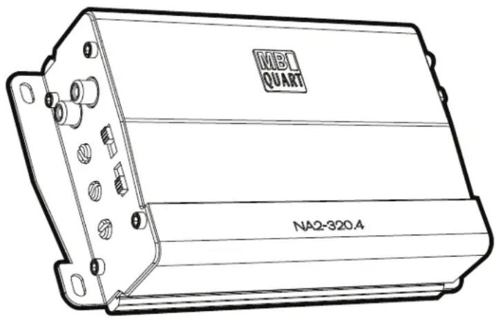
NA2-320.4
NA2-400.11
NA2-500.5
Congratulations on your choice of a MBQuart amplifier. This “Quick Start Installation” guide is meant to help you “hook up” and play music. For more detailed information, on system setting, speaker and subwoofer configuration and full specifications by model visit the website, http://mbquart.com/manuals.html
Before you start

CAUTION

Many new and factory radios require a reset code when disconnected from battery power. This is an anti-theft feature. Before unplugging power, you must determine if your radio/source unit requires a reset code. Check the operation manual for your vehicle or contact the dealer.
Power cable size and fusing
It is critical to use the proper power and ground cable. Select the size listed here for your amplifier model. Always use high quality copper cable. Visit our website for multi amp system cable recommendations.
Be sure to use the proper fuse size for each model. Some models require an external fuse.
Model
Fuse Size
Cable Size
NA2-400.2
1-30A atc
NA2-320.4
1-30A atc
NA2-400.1
1-30A atc
NA2-500.5
1-40A atc
10ga
For power cable runs over 20 feet, 8ga is recommended.
Installation

Disconnect Negative Battery Terminal
Place terminal in a secure position so that it won't accidentally contact the negative battery post
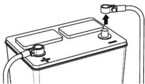
natural_image
Line drawing of a battery with two terminals and a switch, connected to wires (no text or symbols)
Run Cables
Properly route power, speaker and RCA cables through the vehicle.
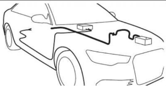
natural_image
Line drawing of a car with visible battery pack and wiring (no text or symbols)
Mount Amplifier
Choose a mounting location that will provide adequate air ventilation. Mount the amplifier to a secure surface. Do not mount the amplifier upside down.
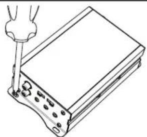
natural_image
Line drawing of a handheld electronic device with a screwdriver inserted (no text or symbols)
Chassis Ground

The chassis ground connection is critical to the performance of the amplifier. Choose a location that is close to the amplifier. Completely scrape away the paint and use a nut and bolt if possible. DO NOT USE AN EXISTING FACTORY BOLT!
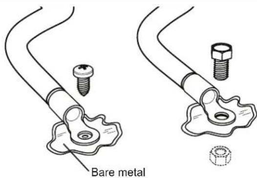

Power Connection
Attach the chassis ground, +12V and remote wire. It is important to make sure these connections are very secure.
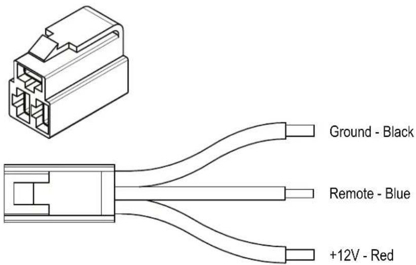

Signal Input Connection
Connect the RCA cables to the INPUT connectors. The OUTPUT can be used to provide input for a second amplifier.

natural_image
Technical line drawing of a coaxial cable with two separate labeled components (L and R), no text or symbols present.
Gain Control

Turn the GAIN control completely counter-clockwise to minimum.

8
Speaker Connections
Connect the speaker cables to the speaker output connectors. Follow the diagram below that best fits your speaker configuration.
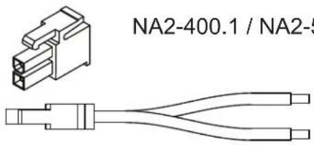
Speaker Positive - Gray Speaker Negative - Gray / Black
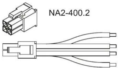
Left Positive - White Left Negative - White / Black
Right Positive - Gray Right Negative - Gray / Black
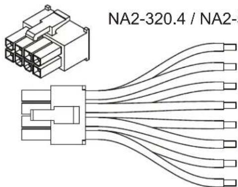
Left Front Positive - White Left Front Negative - White / Black
Right Front Positive - Gray Right Front Negative - Gray / Black
Left Rear Positive - Green Left Rear Negative - Green / Black
Right Rear Positive - Purple Right Rear Negative - Purple / Black
9
Positive Battery Connection
Connect the power cable to the positive battery terminal. The power cable must be fused within 18 inches of the battery terminal.
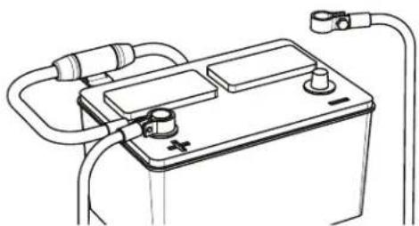
natural_image
Line drawing of a battery with two leads and a terminal connector (no text or symbols)
Be prepared to disarm your vehicle's alarm and to enter your radio / source unit code.

10
Re-connect
Negative Battery
Terminal
Re-connect the negative battery terminal making sure it is securely tightened.
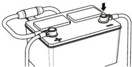
natural_image
Line drawing of a battery with two plates and connecting tubing (no text or symbols)
Settings
The illustrations below describe the various controls. Refer to the illustration that matches your amplifier.
① GAIN Adjustment
The gain control purpose is to match the output of your source signal to the amplifier. Refer to the section B below for detailed instructions.
②X-OVER Switch
This switch will set the amplifier to have a full frequency output or to filter out high or low frequencies. The NA1-400.2 offers either a bandpass or a high pass filter.
③ Frequencies Adjustment
The Low Pass Filter will cut off the frequencies above the setting. The High Pass Filter will cut off the frequencies below the setting.
④ SUBSONIC Adjustment
The Subsonic Filter will cut off the frequencies below the setting. If using with a subwoofer the settin should be kept between 15-25Hz.
⑤ BOOST Switch

The Boost Switch will increase the signal 12dB at 45Hz. Be aware this setting can cause distortion if the gain is not set properly.
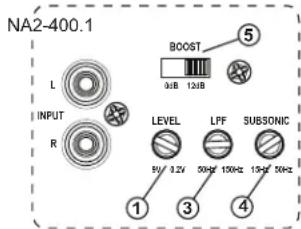
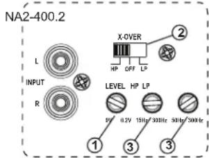


Level Setting

This is a critical step to insure your amplifier is properly adjusted to match the signal output level of your source unit.
THIS IS NOT A VOLUME CONTROL!
GAIN

MINMAX
- If possible, with the source unit off, confirm that the primary volume control is turned down (counter clockwise).
- Turn on the source unit (CD, or MP3 player). Re-confirm that the volume is turned down. Make sure the source unit controls; balance, fader, bass and treble are all set to center or "0" adjustment. Make sure that the green LED on the end of the amplifier is illuminated.
- Play a clean musical selection of which you are very familiar. CD is preferred. Do not use radio signals for level setting. Hit play and start turning the volume of the source unit up.
- Stop increasing the source unit volume when you reach 3/4 (about 75%) or until you hear speakers begin to slightly start producing distortion.
- Increase the amplifier gain (clockwise) until distortion is heard, then back the level down (counter clockwise) until the distortion is eliminated. Small adjustments may need to be made to balance the levels of multiple amplifiers.

Remote Level Control
Some models include a bass remote. Avoid adjusting the bass remote while operating vehicle.

natural_image
Pure electrical circuit lines without any symbols


MBQuart.com
#MUSIC DEFINED
The information contained within this document is intended to offer some basic guidelines for a few of the most common installations. More complex audio systems should be installed by a competent professional. Additional installation information available at www.maxxsonics.com
WARRANTY
Maxxsonics USA Inc. warrants this product, to the original consumer purchaser, to be free from defects in material and workmanship for a period of one (1) year from the date of purchase. Maxxsonics USA Inc. will, at its discretion, repair or replace defective products during the warranty period. Components that prove to be defective in materials and workmanship under proper installation and use must be returned to the original authorized Maxxsonics USA Inc. retailer from where it was purchased. A photocopy of the original receipt must accompany the product being returned. The costs associated with removal, re-installation and freight are not the responsibility of Maxxsonics USA Inc. This warranty is limited to defective parts and specifically excludes consequential damages connected therewith. To view the full warranty, please visit the website.
any incidental or
MBQuart products are designed and engineered in the USA by
MAXXSONICS®
- MBQX-STG2-RAD-1
- CAN-AM MAVERICK X3 STAGE 2 / 400 WATT / TWO SPEAKER UTV-TUNED AUDIO PACKAGE
- INSTALLATION OVERVIEW VIDEO
- WHAT'S INCLUDED
- What's In The Box?
- WARRANTY
- TECHNICAL SUPPORT
- INSTALLATION TIME
- TOOLS AND SUPPLIES NEEDED
- SAFETY PRECAUTIONS
- PREPARATION FOR INSTALLATION & DISASSEMBLY
- REMOVE SEATS - DISCONNECT BATTERY
- VEHICLE DISASSEMBLY
- DISASSEMBLY IS COMPLETE!
- WIRING HARNESS PREP
- ROUTE WIRING HARNESS
- SOURCE UNIT PREPARATION AND WIRING
- AMPLIFIER INSTALLATION
- OPTIONAL SUBWOOFER INSTALLATION
- FRONT SPEAKER INSTALLATION
- \*AFTERMARKET ROLL CAGES
- FRONT SPEAKER INSTALLATION (Continued)
- DOUBLE CHECK INSTALLATION STEPS TO THIS POINT
- AMPLIFIER SETTINGS
- STEP 1 - ADJUST TWO-CHANNEL AMPLIFIER
- STEP 2 - ADJUST MONO AMPLIFIER
- INITIAL TESTING
- STEP 1 - RECONNECT THE BATTERY
- STEP 2 - CONNECT SOURCE UNIT
- STEP 3 - INSERT MAIN FUSE AT BUS BAR
- STEP 4 - TURN ON IGNITION
- STEP 5 - INITIAL CHECKS
- FINE TUNING
- A Settings
- ① GAIN Adjustment
- ② X-OVER Switch
- ③ Frequencies Adjustment
- ④ SUBSONIC Adjustment
- ⑤ BOOST Switch
- B Level Setting
- THIS IS NOT A VOLUME CONTROL!
- VEHICLE REASSEMBLY
- FINAL INSPECTION
- COMPLETE WIRING LAYOUT
- NOTES
- MBQuart.com #MUSIC DEFINED
- FCC Notice
- MBQUARTI® MUSIC. DEFINED.
- GMR-LED
- AM/FM/USB/Bluetooth®
- Multimedia Controller
- for Off-Road and Marine
- CAUTION
- General Information
- Powersports and Marine Multimedia Source Unit
- Auxiliary A/V Sources
- AM / FM / Weather band Section
- USB / AUX / Bluetooth Audio Section
- Audio Section & Other Features
- Installation Specifications
- Wiring and Connections
- Preamp Level Audio Connections
- Rear Mounting Instructions
- Installation Opening & Depths Mounting Bracket Details
- Front Mounting Instructions
- Front Panel Controls
- POWER/Selector and Volume Knob
- SOURCE Button
- 1/ ✱ Button
- 2/INT Button
- 3/RPT Button
- 4/RDM Button
- Scan Down for AM/FM or Track Back for USB/Bluetooth source.
- Mute for AM/FM and AUX or Play/Pause for USB/Bluetooth source.
- Scan Up for AM/FM or Track Up for USB/Bluetooth source.
- AM/FM Configuration
- Settings Choices for AM
- Settings Choices for FM
- Weather Band Operation
- Bluetooth Pairing
- Pairing a Bluetooth device:
- Included in Bluetooth Play Screen:
- If a PIN Code is Required:
- Automatically Connecting:
- Manually Disconnecting:
- USB Thumb Drive Screen:
- USB Smartphone Screen:
- USB RPT and RDM Functionality
- USB Thumb Drive RPT and RDM
- USB Smartphone RPT and RDM
- Auxiliary (AUX) Input and Camera
- Camera Operation
- SETTINGS Menu
- Equalization (EQ)
- Clock Mode
- SETTINGS Menu (Continued)
- Clock Adjust
- Backlight
- Version
- AUDIO Settings Sub-Menu
- SUB Frequency
- SUB Level
- ZONE Level
- BASS Level
- TREBLE Level
- BALANCE Control
- FADER Control
- Factory Reset
- Video Output Feature
- Audio System Design Ideas
- MBQuart.com
- #MUSIC DEFINED
- STAGE 2 / 400 WATT / TWO SPEAKER UTV-Tuned Audio Package for Can-Am Maverick X3 Vehicles
- Quick Start Installation Guide
- Before you start
- Power cable size and fusing
- Installation
- Disconnect Negative Battery Terminal
- Run Cables
- Mount Amplifier
- Chassis Ground
- Power Connection
- Signal Input Connection
- Gain Control
- Settings
- ②X-OVER Switch
- Level Setting
Brand : MB QUART
Model : MBQX-STG2-RAD-1
Category : Loudspeaker