
99-7413 - Car accessories Metra - Free user manual and instructions
Find the device manual for free 99-7413 Metra in PDF.

| Product Type | Car Audio Installation Kit |
| Brand | Metra |
| Model | 99-7413 |
| Compatible Vehicles | Nissan Altima (1993-1997, 1998-2001) |
| Head Unit Types | DIN, ISO-DIN, with optional equalizer |
| Included Components | Radio Housing, Mounting Brackets, Faceplate, ISO-DIN Spacers, Equalizer Dummy Plate, DIN Cage, Screws (4 flat-head, 6 self-tapping) |
| Material | Plastic, Metal |
| Dimensions (approx.) | 7 x 5 x 4 inches (standard DIN size) |
| Weight (approx.) | 0.5 lbs (0.23 kg) |
| Installation Location | Dashboard center console (replaces factory radio) |
| Wiring Connection | Requires mating adaptor (sold separately); tape unused wires |
| Tools Required | Phillips screwdriver, cutting tool, wrench |
| Safety Precaution | Disconnect negative battery terminal before installation |
| Maintenance | Periodically check screws; clean with dry cloth |
| Repairability | Replacement parts available from Metra |
| Manufactured by | Metra Electronics Corporation |
Frequently Asked Questions - 99-7413 Metra
User questions about 99-7413 Metra
0 question about this device. Answer the ones you know or ask your own.
Ask a new question about this device
Download the instructions for your Car accessories in PDF format for free! Find your manual 99-7413 - Metra and take your electronic device back in hand. On this page are published all the documents necessary for the use of your device. 99-7413 by Metra.
USER MANUAL 99-7413 Metra


(4) 5mm Flat-head
Screws

(6) #6 Self-tapping
Screws


TOOLS REQUIRED

Phillips screwdriver

Cutting tool

Wrench
99-7413 INSTALLATION INSTRUCTIONS
APPLICATIONS
CAR PAGE
NISSAN
Altima 1993-97....1
Altima 1998-01....2

natural_image
Illustration of a classic car with musical notes floating around it (no text or symbols)1-800-221-0932 www.metraonline.com
© COPYRIGHT 2001 METRA ELECTRONICS CORPORATION
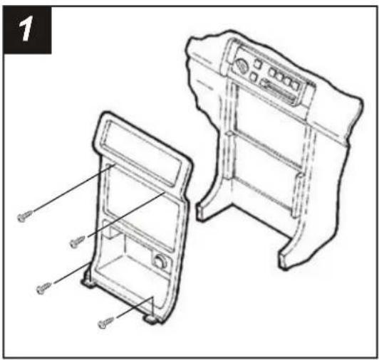
NISSAN Altima 1993-97

natural_image
Technical line drawing of two mechanical components with mounting brackets and ventilation grilles (no text or symbols)Disconnect the negative battery terminal to prevent an accidental short circuit. Remove the shifter cover and (4) Phillips screws exposed. Remove (2) screws from the driver's side knee bolster and lower. Remove (1) screw from the left corner of the radio triim bezel. Remove (2) screws above the radio opening and unclip the bezel. Remove (4) screws from the factory head unit assembly and disconnect the wiring.

Using the raised lines as a guide, cut and remove the ends of each Mounting Bracket ("A").

natural_image
Technical line drawing of a mechanical assembly with labeled components (no text or symbols present)Align the holes in the Mounting Brackets with the holes in the Radio Housing and mount with (6) #6 Self-tapping Screws supplied.

natural_image
Technical line drawing of a mechanical assembly with two views: top view showing internal components and bottom view showing internal parts (no text or symbols)Remove (4) screws securing the cupholder to the factory head unit assembly and remove. Slide the cupholder into the bottom of the Radio Housing and mount with the same (4) screws. Skip to the Installation Instructions for ALL VEHICLES on Page #3.
NISSAN Altima 1998-01
natural_image
Technical line drawing of two mechanical components with labeled parts, no text or symbols presentDisconnect the negative battery terminal to prevent an accidental short circuit. Unclip the gear shifter trim bezel and remove (2) Phillips screws exposed. Remove (2) Phillips screws above the radio opening. Unclip the radio trim bezel. Remove (4) Phillips screws from the factory head unit and disconnect the wiring.

Locate the corner of each lower mounting tab on the Mounting Brackets ("A").
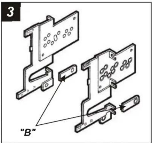
Using the corner of each mounting tab as a guide, cut and remove the ends of the cupholder mounts from the Mounting Brackets ("B").

natural_image
Technical line drawing of a mechanical assembly with labeled components (no readable text or symbols)Align the OUTER holes in the Mounting Brackets with the holes in the Radio Housing and mount with (6) #6 Self-tapping Screws supplied. (The Brackets will mount on an angle). Skip to the Installation Instructions for ALL VEHICLES on Page #3.
ALL VEHICLES

DIN HEAD UNITS: Slide the DIN cage into the Housing and secure by bending the metal locking tabs down. Slide the aftermarket head unit into the cage until secure. (see Fig. B)
ISO-DIN HEAD UNITS: Cut and remove the shaft supports from the Faceplate. Snap the Faceplate into the Housing and attach the ISO-DIN Spacers to the inner walls of the Mounting Brackets by inserting the Spacer pegs into the Bracket holes. Slide the aftermarket head unit into the back of the kit and mount the Brackets to the unit with (4) 5mm Flat-head Screws supplied. (see Fig. C)
(If an equalizer will be included, slide the unit into the back of the Radio Housing and secure. If an equalizer will NOT be included, snap the Equalizer Dummy Plate into the opening).

Locate the factory wiring harness in the dash. Metra recommends using the proper mating adaptor and making connections as shown. (Isolate and individually tape off the ends of any unused wires to prevent electrical short circuit).

Re-connect the battery terminal and test the unit for proper operation. Mount the head unit/kit assembly to the sub-dash with (4) Phillips screws removed in step #1.
Brand : Metra
Model : 99-7413
Category : Car accessories