
GW21606 - Electrical Modular System Gewiss - Free user manual and instructions
Find the device manual for free GW21606 Gewiss in PDF.

| Product Type | Modular electrical system for domestic and similar use |
| Installation | Surface-mounted, flush-mounted, in ordinary and watertight boxes (IP55) |
| Modularity | Frames up to 12 modules; includes controls, socket-outlets, protections, indicators, connectors |
| Reference Standards | EN 60669-1, IEC 60884-1, EN 60898-1, EN 61009-1, EN 60730-1, etc. |
| Rated Voltage | 230V AC (50/60 Hz) for most components; some 12/24V AC/DC |
| Protection Degree (IP) | IP41 (closed front), IP21 (open front, e.g. socket-outlets), IP4X (with plug inserted) |
| Terminal Capacity | Stranded wires: min 0.75 mm², max 2×4 mm²; Solid wires: min 0.5 mm², max 2×2.5 mm² |
| Terminal Resistance to Traction | >50 N |
| Device Hold on Support | >0.6 J |
| Glow Wire Test (Commands) | 850°C |
| Breaking Capacity (MCBs) | 3 kA |
| Residual Current Circuit Breaker | Class A, 10-30 mA, 3 kA |
| Dimmer Types | Rotary, push-button (TRIAC and IGBT), for resistive/inductive loads |
| TV-SAT Socket-Outlets | Frequency range 5-2400 MHz, shielding Class A, 75 ohm impedance |
| Telephone Connectors | RJ11, 4 contacts, Category 3, up to 16 Mb/s |
| Data Connectors (RJ45) | Categories 5e and 6, shielded/unshielded, insulation displacement connection |
| USB Charger | 2.1A dual USB, input 100-240V AC, output 5V DC, 2.1A total |
| Overvoltage Limiter | Varistor, 250V AC, 8 kA (8/20 μs), 75 J |
| Gas Detectors | Methane and LPG, 12V AC/DC, alarm threshold 9% LIE, 85 dB at 1m |
| Anti-Blackout Lamp | Flush-mounting or extractable, Ni-Mh battery, min 1-2h autonomy, white LED |
| Maintenance | Keep dry and dust-free; do not install near thermostats; max 1-2 regulators per box with derating |
| Operating Temperature | Typically 0 to +40°C (some devices -5 to +45°C) |
| Spare Parts / Accessories | LED lamps, diffusers, adapters, blanking modules, fuse carriers, etc. |
Frequently Asked Questions - GW21606 Gewiss
User questions about GW21606 Gewiss
0 question about this device. Answer the ones you know or ask your own.
Ask a new question about this device
Download the instructions for your Electrical Modular System in PDF format for free! Find your manual GW21606 - Gewiss and take your electronic device back in hand. On this page are published all the documents necessary for the use of your device. GW21606 by Gewiss.
USER MANUAL GW21606 Gewiss
General characteristics
A modular range of devices for domestic and similar use which can be installed in surface- or flush-mounting boxes and in ordinary and watertight boxes.
The System range for domestic use has a modular structure on flush-mounting frames up to 12 modules. Surface-mounting and free-standing boxes and plates are included, along with watertight plates (IP55) and outdoor containers (IP40 and IP55).
The range includes controls, socket-outlets, protections, indicators, connectors and special components with high quality characteristics.
TECHNICAL DATA AND REFERENCE STANDARDS
| Component Reference standards | Essential electrical data* | Prolonged operation(no. position changes) | Resistance to abnormal heat and fire | |||
| Resistance at test voltage (V) | Insulation resistance (MΩ) | Breaking capacity or category of use | Thermo-pressure with ball (°C) | Glow Wire Test (°C) | ||
| Commands EN 60669-1 | 2000at 50 Hz for 1 minute | >5 | 1.25 In(200 position changes) | 40,000at In 250V AC cos φ = 0.6 | 125 850 | |
| Socket-outlets | IEC 60884-1 | 1.25 In(100 position changes) | 10,000at In 250V AC cos φ = 0.8 | |||
| Latching relays | EN 60669-1 / EN 60669-2-2 | 50,000at In 250V AC cos φ = 0.6 | ||||
| Momentary relays | EN 60669-1 / EN 60669-2-2 | 1.25 In(200 position changes) | ||||
| Miniature circuit breakers | EN 60898-1 | 2^** ÷ 5 | 3KA | 8,000 | ||
| Residual current circuit breakers | EN 61009-1 / EN 61008-1 | 3KA | 4,000 | |||
| Supports and plates | EN 60669-1 | - | - | - | 70 | 650 |
* For rated voltages and currents, see the specifications in the single codes. ** The value of 2 MΩ refers to a special condition established by the standards given alongside.
BEHAVIOUR WITH CHEMICAL AND ATMOSPHERIC AGENTS
| Component\Agent | Water | Saline solution | Acids Bases Solvents | Mineral oil | UV rays | |||||||
| Concentrated | Diluted | Concentrated | Diluted | Hexane | Benzol | Acetone | Ethyl alcohol | |||||
| Plates Resistant | Resistant | Limited resistance | Resistant | Resistant | Resistant | Limited resistance | Not resistant | Not resistant | Not resistant | Limited resistance | Resistant | |
| SYSTEM devices | Resistant | Limited resistance | Not resistant | Limited resistance | Limited resistance | Resistant | Resistant | Resistant | Resistant | Resistant | ||
* The resistance values given are valid for an ambient temperature no higher than 40°C.
Terminal resistance to cable traction: >50N Device hold on support: >0.6J
TERMINAL TIGHTENING CAPACITY
| Stranded wires Solid wires | |||
| Minimum 0.75mm^2 | Maximum 2 × 4mm^2 | Minimum 0.5mm^2 | Maximum 2 × 2.5mm^2 |
Common construction features

natural_image
Technical line drawing of an internal electrical or mechanical device housing (no text or symbols visible)Quick installation: fixing the devices on the supports from both front or rear.
Simplicity of connections: double terminals, cable clamp with unlosable screws and protection collars.
SYMBOL DISCS

Miniature lamps

Symbol discs for functional signalling
For technical information contact the Technical Assistance Service or visit gewiss.com
Degree of protection of the set of SYSTEM domestic range assembly installed
| COMPONENT INSTALLATION REFERENCE STANDARD IP RATING | |||
| Devices with closed front (commands, bells, indicators, etc.) installed in flush-mounting boxes, surface-mounting boxes, free-standing panels (completed with support and plate) and in self-supporting boxes | Flush-mounting for domestic or similar finish, in vertical position, installed to a high standard | EN60529 | 41 |
| Devices with open front (socket-outlets, etc.) installed in flush-mounting boxes, surface-mounting boxes, free-standing panels (completed with support and plate) and in self-supporting boxes | Flush-mounting for domestic or similar finish, in vertical position, installed to a high standard. Suitable for use for zone 3 of rooms containing baths or showers. | X1(it is 21 in case of socket-outlets) | |
| Devices with open front (socket-outlets, etc.) installed in flush-mounting boxes, surface-mounting boxes, free-standing panels (completed with support and plate) and in self-supporting boxes | Flush-mounting for domestic or similar finish, in vertical position, installed to a high standard with plug inserted | 4X | |
ACCESSORIES
Spare parts and accessories
Lamps for System articles
| CONTROL DEVICES MINIATURE LAMP UNITS | Luminous / colour RESULT | OBTAINABLE COLOURS | |||||||
| Functional Functional localisation | Iconographic signalling | Type Code Voltage Colour | |||||||
| LED | GW 10 893 12-24V AC/DC | White | The signalling colour corresponds to the colour of the chosen miniature lamp | White | |||||
 | [XXHX] |  | GW 30 947 230/110V AC | ||||||
| GW 30 946 230/110V AC Light blue | Light blue | ||||||||
| Fluorescent | GW 30 943 230V AC Red Red | ||||||||
| GW 30 944 | 230V AC | Green | Green | ||||||
| PUSH-BUTTON WITH NAME PLATE | CARTRIDGE LAMPS | Luminous / colour RESULT | OBTAINABLE COLOURS | ||||||
 | Type Code Voltage Colour | ||||||||
| Incandescent S6 x 36 | GW 20 902 | 12V AC/DC | White | White backlighting | White | ||||
| GW 20 903 | 24V AC/DC | ||||||||
| SINGLE INDICATOR LAMPS | CARTRIDGE LAMPS | Luminous / colour RESULT | OBTAINABLE COLOURS | ||||||
 | Type Code Voltage Colour | ||||||||
| Incandescent S6 x 31 | GW 20 904 | 12V AC/DC | White | The signalling colour corresponds to the colour of the chosen indicator lamp diffuser | Red - Green Amber - White Light blue | ||||
| GW 20 905 | 24V AC/DC | ||||||||
| Fluorescent S6.3 x 28 | GW 20 906 | 230V AC | Red | With red diffuser: | Red | ||||
| With amber diffuser: | Amber | ||||||||
| GW 20 908 | Green | With green diffuser: | Green | ||||||
| STAIR RISER LAMPS | CARTRIDGE LAMPS | Luminous / colour RESULT | OBTAINABLE COLOURS | ||||||
 | Type Code Voltage Colour | ||||||||
| Incandescent S6 x 36 | GW 20 902 | 12V AC/DC | White | The signalling colour corresponds to the colour of the chosen stair riser lamp diffuser | Red - Green Amber - White Light blue | ||||
| GW 20 903 | 24V AC/DC | ||||||||
Examples of functional and localisation lighting
To indicate the operating status of services not visible from the command position
The indicator lamp is located parallel to the service, and is switched on when the one-way switch is DN. The indicator lamp follows the CN/OFF status of the service.


The two indicator lamps and the service are placed in parallel, therefore they switch on and off together with the service
To locate the command button key in the dark
The indicator lamp is switched on when the one-way switch is OFF. With the one-way switch in the ON position, the service is powered and the indicator lamp is switched off.


The two indicator lamps come on when the service is not powered and go off when it is ON.
NOTE: layouts not suitable for commanding compact energy saving lamps. LED lamps and/or relays
For technical information contact the Technical Assistance Service or visit gewiss.com
COMMAND
Infrared movement detector
The passive infrared movement detector senses temperature variations within its range of action and, depending on the environmental light, closes a relay contact. When movement stops, the contact automatically opens again after an adjustable set time. The device incorporates a light-sensitive sensor with an adjustable tripping threshold to avoid controlling the service (e.g. lighting equipment) when not necessary.
Reference standards: EN 60669-1; EN 60669-2-1

Connection diagram

DATI TECNICI
| Power supply voltage | 230V - 50/60Hz |
| Light-sensitive threshold setting | 10 lux - max. inhibited |
| Activation duration setting | 15 sec / 10 min |
| Output contact | 1 NA 3A (AC1) 250V ac, potential-free |
| Type of load: | |
| Resistive loads | 700W |
| Incandescent lamps | 450W |
| Low voltage halogen lamps (12V) | 450W |
| Uncompensated fluorescent lamps | 2x58W |
| Motor and motor reduction units | 400VA |
| Operating temperature | -5 / +40 °C |
| Relative humidity | max. 93% non condensative |
Not suitable for compensated fluorescent lamps, for discharge lamps and for those loads not indicated; please use an auxiliary relay to control such lamps.
Applications
Stairway lighting control | Display area lighting control | Garage/entrance lighting control |  |
Relay
Latching relay
Latching-type relay for controlling lamps from several points using push-buttons with NO contact.
Momentary relay
For executing automatic mechanisms or separations between the control circuit and the power circuit. Can be used as an auxiliary element for controlling particular loads.
| LATCHING RELAY MOMENTARY RELAY | |||||
| Reference standards:EN 60669-1; EN 60669-2-2 |  | System: GW 20 071GW 21 071GW 20 072GW 21 072Playbus: GW 30 111 | Reference standards:EN 60669-1; EN 60669-2-2 |  | System: GW 20 074GW 21 074Playbus: GW 30 116 |
TECHNICAL DATA
| Power supply voltage (coil) | 230V - 50/60Hz | Power supply voltage (coil) | 230V - 50/60Hz |
| Output contact | GW 20 071 / 21 071 / 30 111 1NO; | Output contact | 1 changeover contact NO/NC; |
| GW 20 072 /21 072 / 2NO | 10A (AC1) / 4A (AC15) - 250V AC | ||
| 10A (AC1) / 7A (AC15) - 250V AC |
Latching relay contact diagram Momentary relay

For technical information contact the Technical Assistance Service or visit gewiss.com
Call relay
"Bathroom Alarm" call system
For the locations where it is compulsory (bathrooms), space must be allowed for the manoeuvring of a wheel chair, and an emergency bell must be fitted near the toilet and bathtub.
Connection diagram

Multiple call system
For small concerns (school classrooms, clinics, nursing homes, etc.) where the call must be localised from the control station.

Call display board located in the control station.
Connection diagram

flowchart
graph TD
    subgraph Room 1 ROOM 2
        A1["Room 1 Lamp outside the door"] --> B1["Call push-button"]
        B1 --> C1["Al. NO NC Call relay"]
        C1 --> D1["+"]
        D1 --> E1["Room 2"]
        E1 --> F1["Call push-button"]
        F1 --> G1["Al. NO NC Call relay Lamp"]
    end

    subgraph Room 2 ROOM 3
        H1["Room 1"] --> I1["A1 15 room 1"]
        I1 --> J1["A2"]
        J1 --> K1["Timer GW 96 814"]
        K1 --> L1["Momentary relays GW 06 601"]
        L1 --> M1["Ringer GW 96 401"]
        M1 --> N1["Indicator lamps GW 96 586"]
        N1 --> O1["Room 3"]
        O1 --> P1["Call push-button"]
        P1 --> Q1["Al. NO NC Call relay"]
        Q1 --> R1["+"]
        R1 --> S1["Room 3"]
    end

    subgraph Room No.
        T1["Room 2"] --> U1["Call push-button"]
        U1 --> V1["Al. NO NC Call relay Lamp"]
        V1 --> W1["+"]
        W1 --> X1["Room 2"]
        X1 --> Y1["Call push-button"]
        Y1 --> Z1["Al. NO NC Call relay Lamp"]
        Z1 --> AA["+"]
        AA --> AB["Room 3"]
    end

    C1 --> M1
    M1 --> N1
    N1 --> O1
    O1 --> P1
    P1 --> Q1
    Q1 --> R1
    R1 --> S1
    S1 --> T1
    T1 --> U1
    U1 --> V1
    V1 --> W1
    W1 --> X1
    X1 --> Y1
    Y1 --> Z1
    Z1 --> AA
    AA --> AB
    AB --> T1
    T1 --> U1
    U1 --> V1
    V1 --> W1
    W1 --> X1
| CALL RELAY | ||
| Reference standards: EN 60669-1;EN 60669-2-2 | GW 20 076 GW 21 076 | |
| TECHNICAL DATA | ||
| Power supply voltage (coil) 12V AC / 12V DC | ||
| Output contact 1NO/NC 12V | ||
For technical information contact the Technical Assistance Service or visit gewiss.com
SIGNAL
TV-SAT socket-outlets
The development of television transmission systems and of services intended for the user has raised the performance and quality level required for signal distribution systems.
The EN 60728 standards (systems for distribution of television and sound signals via cable) define the present and future European Standard and establish the requisites that the various parts of the system (including the terminal socket-outlets) must meet.
Thanks to their high performance level, these new socket-outlets provide optimal distribution of the signals (both digital and analogue), as required by the various providers for accessing current and future services.

CHARACTERISTICS ADVANTAGES
| • Shielding efficiency (in compliance with standard EN 60728-4. |
| • Impedance adaptation. |
| • An innovative system for the quick, safe connection of the coaxial cable. |
| • A range featuring two types:user ports with F connector (type EN 60169-24) and with male IEC connector ∅ 9.5mm (in compliance with HD 134.2 S2). |
• The socket-outlets are in a metal shell and are unaffected by the electromagnetic emissions (EMC) present in the environment.
- Undesired signal reflections are avoided.
- Maintains the co-axiality of the cable in the connection point.
- Maximum application flexibility with single or centralised systems (new / restored / pre-arrangements for future extensions).
- In satellite reception, due to the frequency range, it is very important to maintain the co-axiality of the connection, which is a requirement fully met by the innovative connection and the use of the F connector.
| APPLICATIONS | TV SAT TV-SAT | |||||||
| Centralised system with star distribution | Centralised system with cascade distribution | SAT system for single service | Combined TV-SAT system for single service | Combined TV-SAT centralised system with star distribution | Combined TV-SAT centralised system with feedthrough socket-outlets | |||
| System:GW 20 391GW 20 396GW 20 392GW 20 393 |  | Playbus:GW 30 311GW 30 316GW 30 312 | 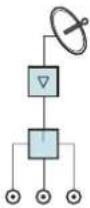 Direct socket outlets Direct socket outlets |  |  |  | ||
| System:GW 20 381GW 20 386GW 20 382GW 20 383 | (ZHTD) | Playbus:GW 30 301GW 30 306GW 30 302 | TV SAT | | | |||
Reference standards: EN 50083-1; EN 50083-2; EN 50083-4
Resistance of terminal closure: 75 ohm

GW 20 277
| TECHNICAL DATA | |
| Frequency field From 5 to 2400 MHz | |
| Diameter of the coaxial cable From ∅ 5 to ∅ 7mm | |
| Return channel From 5 to 40 MHz | |
| Shielding Class A | |
| Chrominance/luminance delay difference | <1 ns. for all models |
| TV port male IEC coaxial connector ∅ 9.5mm | |
| SAT port F (female) coaxial connector | |
For technical information contact the Technical Assistance Service or visit gewiss.com
TV-SAT socket-outlets attenuation values
| Gewiss code | Nominal attenuation (dB) | Attenuation / Loss of passage (flattening of response) | Branching attenuation / Loss of base (flattening of response) | Directivity | Return loss (dB) | ||||||||
| Return channel | TV SAT | Return channel | TV SAT | Return channel | TV-SAT | Return channel | TV-SAT | ||||||
| 5-40 MHz | 47-862 MHz | 950-2150 MHz | 2150-2400 MHz | 5-40 MHz | 47-862 MHz | 950-2150 MHz | 2150-2400 MHz | 5-40 MHz | 47-2400 MHz | 5-40 MHz | 47-2400 MHz | ||
| GW 20 391 - GW 20 381GW 21 391 - GW 21 381GW 30 311 - GW 30 301 | 0 ---- | ≤ 0.5 dB(≤ 0.2 dB) | ≤ 0.5 dB(≤ 0.5 dB) | ≤ 0.8 dB(≤ 0.5 dB) | ≤ 0.8 dB(≤ 0.5 dB) | --- ≥ 10 dB | complying with CEI-EN 50083-4 | ||||||
| GW 20 392 - GW 20 382GW 21 392 - GW 21 382GW 30 312 - GW 30 302 | 10 | ≤ 2.5 dB(≤ 1 dB) | ≤ 2 dB(≤ 1 dB) | ≤ 3 dB(≤ 1.5 dB) | ≤ 3.2 dB(≤ 1.5 dB) | 10.5 dB(± 1.5 dB) | 10dB(± 1.5 dB) | 10.5 dB(± 1.5 dB) | 11dB(± 2.5 dB) | ≥ 15 dB | complying with CEI-EN 15083-4 | ≥ 10 dB | |
| GW 20 393 - GW 20 383GW 21 393 - GW 21 383GW 30 313 - GW 30 303 | 14 | ≤ 1.5 dB(≤ 1 dB) | ≤ 1.2 dB(≤ 1 dB) | ≤ 2.2 dB(≤ 1.5 dB) | ≤ 2.5 dB(≤ 1.5 dB) | 15 dB(± 1.5 dB) | 14.5 dB(± 1.5 dB) | 14.5 dB(± 1.5 dB) | 15 dB(± 2.5 dB) | ≥ 15 dB ≥ 15 dB | |||
| Insulation / separation between ports | |||||||||||||
| GW 20 396 - GW 20 386GW 21 396 - GW 21 386GW 30 316 - GW 30 306 | 5 | ≤ 5 dB(≤ 1.5 dB) | ≤ 5 dB(≤ 1.5 dB) | ≤ 6 dB(≤ 1.5 dB) | ≤ 6.5 dB(≤ 1.5 dB) | ≤ 5 dB(≤ 1.5 dB) | ≤ 5 dB(≤ 1.5 dB) | ≤ 6 dB(≤ 1.5 dB) | ≤ 6.5 dB(≤ 1.5 dB) | >12 dB >10 dB ≥ 10 dB | EN 50083-4 Degree 3 | ||
Telephone connectors
4-contact RJ11 telephone connectors, suitable for connecting the telephone, telefax, and modem.

Reference standards: ISO 11801
System: GW 20 251 GW 21 251 Playbus: GW 30 261
| TECHNICAL DATA | GW 20 251 - GW 21 251GW 30 261 |
| Connector type RJ11 | |
| No. of contacts 4 | |
| Connection | Terminal blocks with screws |
| Category | 3 |
| Transmission speed | up to 16 Mb/s |
Diagrams

Series connection

flowchart
graph TD
    A["Telephone pair"] --> B["ContactPin 1.2.3.4"]
    A --> C["ContactPin 1.2.3.4"]
    A --> D["ContactPin 1.2.3.4"]
    B --> E["L1"]
    C --> F["L2"]
    D --> G["Terminal"]
    style A fill:#f9f,stroke:#333
    style B fill:#ccf,stroke:#333
    style C fill:#ccf,stroke:#333
    style D fill:#ccf,stroke:#333
Clamps 3 and 4 are connected by means of the contact inside the telephone, which is closed when the telephone receiver is put down. When the telephone receiver is picked up, the line breaks downstream (L1 pole), ensuring that the conversation is not overheard.

Parallel connection

flowchart
graph TD
    A["ContactPin 1.2.3.4"] --> B["L1"]
    C["ContactPin 1.2.3.4"] --> D["L2"]
    E["ContactPin 1.2.3.4"] --> F["Telephone pair"]
    style A fill:#f9f,stroke:#333
    style C fill:#f9f,stroke:#333
    style E fill:#f9f,stroke:#333
Note: when one of the plugs is extracted, the socket-outlets downstream are disconnected. To prevent this problem, insert a plug with a jumper between terminals 3-4, in the socket-outlet from which the telephone appliance was unplugged.
Each socket-outlet takes the signal from the line. There is no conversation secrecy.
For technical information contact the Technical Assistance Service or visit gewiss.com
Connectors for structured wiring
RJ45 connectors in categories 5e and 6, shielded and unshielded for data transmission. They allow network connection of information technology devices (computers, printers, modern, etc.) and the connection of multimedia devices (e.g. those used for video conferences). They can also be used for traditional, centralised telephone systems.
Reference standards: EN 50 173 - ISO 11801 - EIA / TIA 568A

| TECHNICAL DATA | GW 20 686GW 21 686 | GW 20 684 - GW 21 684GW 20 685 - GW 21 685 | GW 20 243GW 21 243 | GW 20 271GW 21 271 |
| Connector type | RJ45 | |||
| Type of usable cables | FTP | UTP | FTP | UTP |
| Number of contacts | 8 | |||
| Terminals | insulation displacement connection (without the need for tools) | |||
| Category | Cat. 6 | Cat. 5e | ||
| Usable transmission protocols | EIA / TIA 568A - EIA / TIA 568B | |||
Diagrams
EIA/TIA - 568A EIA/TIA - 568B

Quick wiring system

GW 20 243 - GW 21 243
GW 20 686 - GW 21 686


Adapters for structured wiring
A data transmission system with structured wiring offers flexibility of use, installation of the final and universal network, commissioning independent of the location and use of the terminal outputs. In complex and extensive systems (e.g. tenders) the client requires a certificate of conformity for the entire system. Leading companies in the field of structured wiring, installed directly or by qualified operators, are able to provide this service. GEWISS, offering a shell which is compatible with IBM, Systimax/Commscope and AMP/Keystone Jack makes it possible to integrate the PLAYBUS / SYSTEM ranges with data transmission components belonging to a structured system.
For technical information contact the Technical Assistance Service or visit gewiss.com
USB and HDMI couplers
Female-female couplers with Keystone Jack coupling, for A-type USB and HDMI cables. To complete with GW2x270 adapters.
HDMI coupler USB coupler

GW 38 056

GW 38 057
USB charger
2.1A double USB charger, suitable for powering mobile phones, smartphones and mobile electronic devices.
Double USB charger

GW 20 361
TECHNICAL DATA
| Power supply 100-240V ac - 50/60Hz - 300mA max | |
| Output 5V dc - 2.1A | |
| USB connector 2.0 A-type | |
| Power supply connector Screw terminals, maximum cable section 1.5 mm ^2 | |
| Degree of protection IP20 | |
| Operating temperature 0 ÷ +40°C | |
Suitable to recharge a single 2.1A electronic device or a couple of simultaneous devices. The total current provided (max. 2.1A) is split in the two USB outputs, depending on the state of charge of the connected devices.
For technical information contact the Technical Assistance Service or visit gewiss.com
PROTECTION
Protection devices
Overvoltage limiter
The overvoltage limiter is a varistor-type discharger suitable for protecting a terminal circuit against mains overvoltages caused by manoeuvres or atmospheric discharges.
Reference standards: EN 61643-11

GW 20 423
GW 21 423
TECHNICAL DATA
| Rated voltage 250V AC | |
| Maximum discharge current 8 kA (8/20 μs) | |
| Maximum discharge power 75 J | |
Operation and connection

The overvoltage peak is absorbed by the varistor which, for voltage values higher than the arcing value, behaves like a resistor with a very low value. The overvoltage peak will not reach the service or will at least be greatly attenuated. If the varistor breaks, a fuse prevents short-circuiting and the fault is indicated by the LED going out.
Automatic circuit breakers
Automatic miniature circuit breakers for protection against overcurrent and earthing currents of terminal circuits.
Miniature circuit breakers Residual current circuit breakers

Reference standards: EN 60898 - EN 61009-1 - EN 61543
TECHNICAL DATA
| Type of circuit breakers | Rated voltage (V) | Rated frequency (Hz) | Rated residual current (mA) | Short-circuiting capacity (A) | Range of nominal currents (A) | No. of poles | Tripping characteristic | ||
| Overcurrent protection | Limiting class | Residual current protection | |||||||
| Miniature circuit breakers | 230 50 - 60 | - 3000 6 - 10 - 16 | 1P1P+N | Type C 3 - | |||||
| Residual current circuit breakers with overcurrent protection | 230 | 50 - 60 | 10 - 30 | 3000 | 6 - 10 - 16 | 1P+N | Type C | 3 | Class A |
For technical information contact the Technical Assistance Service or visit gewiss.com
DIMMER
Rotating electronic regulators, for resistive/inductive loads
Dimmer with conventional potentiometer adjustment and static switching off by turning the knob on position zero.
Reference standards: EN 60669-1; EN 60669-2-1

Typical use:
• Domestic sector for light source adjustment.
| TECHNICAL DATA | GW 20 802 - GW 21 802 - GW 30 402 | GW 20 803 - GW 21 803 - GW 30 403 ( ) | ||
| Technology | with TRIAC | with TRIAC | ||
| Rated voltage at 50/60Hz | 230V | 110V | 230V | 110V |
| Adjustable power | 100-500W | 50-250W | 100-900W | 100-500W |
| Adjustable load | ||||
| - Incandescent and halogen lamps | ● ● ● ● | |||
| - Toroidal and lamellar transformers | ● | ● | ||
| - Manifold engines | ● | ● | ||
▲Items designed solely to export to a limited number of countries outside the European Union or proposed as candidate and to the European Free Trade Association.


The conformity to EMC Directive is guaranteed only connecting the GW 2x 803 or GW 30 403 regulators to a LC filter as showed in the following wiring diagram.


WARNINGS
- The connection should be made together with a fuse carrier (eg. GW 2x 401) with a quick-acting fuse with high breaking capacity type F2.5AH 250Vac (for GW 2x 802 and GW 30 402) or type F5AH 250Vac (for GW 2x 803 and GW 30 403) as shown in the diagrams.
• The regulator does not have a mechanical circuit breaker in the main circuit and so is not galvanically separated. The circuit load should be considered always under voltage.
• The conductors should be pushed down to the bottom of the box. Do not let the conductors in the box contact the walls of the regulator. - Do not install the regulator near thermostats or chronothermostats.
- Max n.1 regulator in the same round/square box. Max n.2 regulators in the same rectangular box; for installations with 2 regulators in the same box, the maximum loads controllable by each regulator should be reduced by 50% . The side-by-side installation of several products in a single box is not permitted; insert a blanking module between two electronic devices.
- It should be used in dry, dust-free places at a temperature between 0^ and +35^ .
For technical information contact the Technical Assistance Service or visit gewiss.com
Rotating electronic regulators with two-way switch, for resistive/inductive loads
Dimmer with incorporated two-way switch that makes it possible to command the switching on and off of a second point (using the two-way switch), or a number of points (using intermediate switches). Switched on and off by pressing the knob; adjustment by turning it.
Reference standards: EN 60669-1; EN 60669-2-1
System: GW 20 811 GW 21 811
Playbus: CW 30 404

| TECHNICAL DATA | GW 20 811 - GW 21 811 - GW 30 404 | |
| Technology | with TRIAC | |
| Power supply voltage at 50/60Hz | 230V | 110V |
| Adjustable power | 40÷300W (GW 30 404)100÷500W (GW 20 811) | 20÷150W (GW 30 404) |
| Adjustable load | ||
| - Incandescent and halogen lamps | • | • |
| - Toroidal transformers | • | • |
| - Lamellar transformers | • | • |
Typical use:
• Domestic sector for light source adjustment.
- In existing systems, the dimmer with two-way switch can be easily installed in place of a two-way switch, without modifying the original circuit.


WARNINGS
• The connection should be made together with a fuse carrier (eg. GW 2x 401) with a quick-acting fuse with high breaking capacity type F2.5AH 250Vac as shown in the diagrams.
- The conductors should be pushed down to the bottom of the box. Do not let the conductors in the box contact the walls of the regulator.
- Do not install the regulator near thermostats or chronothermostats.
- Max n.1 regulator in the same round/square box. Max n.2 regulators in the same rectangular box; for installations with 2 regulators in the same box, the maximum loads controllable by each regulator should be reduced by 50% . The side-by-side installation of several products in a single box is not permitted; insert a blanking module between two electronic devices.
- It should be used in dry, dust-free places at a temperature between 0^ and +35^ .
Push-button electronic regulators, for air agitators
Push-button type dimmer with pre-set intensity levels (0-25-50-100%). By briefly pressing the push-button, the minimum intensity level will be obtained. With any further touch, the speed will change from the minimum to the medium, then the maximum. A subsequent touch will turn the dimmer off.
Reference standards: EN 60669-1; EN 60669-2-1
System: GW 20 818 GW 21 818


Command and adjustment from several points with NO push-buttons
Technical data
Power supply voltage: 230V-50 Hz
Power: 55-80 VA
Typical use:
- Suitable for adjusting air agitators, fans and extractors with induction engines. It can be controlled by external NO push-button.
WARNINGS
- Article only suitable for adjusting air stirrers, fans and aspirators with induction motors with auxiliary phase. Not suitable for adjusting fan-coil motors or light sources.
- The connection should be made together with a fuse carrier (eg. GW 2x 401) with a quick-acting fuse with high breaking capacity type F0.8AH 250Vac as shown in the diagrams.
- The regulator does not have a mechanical circuit breaker in the main circuit and so is not galvanically separated. The circuit load should be considered always under voltage.
- Do not install the regulator near thermostats or chronothermostats.
- It should be used in dry, dust-free places at a temperature between 0^ and +35^ .
For technical information contact the Technical Assistance Service or visit gewiss.com
Push-button electronic regulators, for resistive/inductive loads
Push-button type dimmer, with possibility of control and adjustment from any number of points using single-pole NO push-buttons; gradual switching on and off by briefly touching at the pre-set adjustment level (intensity memory); adjustment with prolonged pressure on the same button. The push-button regulators are available both in traditional and in IGBT technology that allows the regulation of electronic transformers and ensure a quiet and gradual operation.
Reference standards: EN 60669-1;EN 60669-2-1

| TECHNICAL DATA | GW 20 829 - GW 21 829GW 30 407 | GW 20 828 - GW 21 828GW 30 401 |
| Technology | with IGBT transistor | with TRIAC |
| Power supply voltage | 230V - 50Hz | 230V - 50Hz |
| Adjustable power | 25 ÷ 300W (GW 30 406)40 ÷ 300 (GW 20 829)25 ÷ 180W (GW 30 407) | 60 ÷ 500W |
| Adjustable load | ||
| - Incandescent and halogen lamps | • | • |
| - Toroidal transformers | • | • |
| - Lamellar transformers | • | |
| - Electronic transformers | • |
SPECIFIC FUNCTIONAL CHARACTERISTICS OF THE DIMMER GW 20 829 - GW 21 829 - GW 30 407 WITH IGBT TECHNOLOGY
| CHARACTERISTICS | ADVANTAGES |
| • Possibility of commanding electronic power supplies and reduced loads. | • Versatile use. |
| • Memorisation of the adjustment level. | • Easy positioning to a standard adjustment. |
| • Indicator lamp for level of adjustment and protection tripping. | • The indicator lamp allows the device to be identified in the dark; it flashes to show the electronic protection has tripped.• Maximum comfort in selecting the level of adjustment. |
| • Automatic search for the maximum level of adjustment. | |
| • Electronic self-protection against overloading and short-circuiting, resettable. | • Protection of the regulator in the event of overload connections or a fault with the service device.• Total absence of buzzing during operation. |
| • Adjustment with IGBT transistor. |
Typical use:
• Domestic sector, for adjusting light sources
• Commercial sector, hotel rooms, places for communities, conference halls, for adjusting light sources
- In existing systems, the push-button dimmers can be installed in place of two-way switches, without modifying the circuit.


Control and adjustment from several points with NO push-buttons
Before

Two-way switches
Control from two points (2 two-way switches)

Control and adjustment from two points (1 dimmer + 1 NO push-button)
After

WARNINGS
- The connection should be made together with a fuse carrier (eg. GW 2x 401) with a quick-acting fuse with high breaking capacity type F2.5AH 250Vac (for GW 2x 828) or type F1.6AH 250Vac (for GW 2x 829) as shown in the diagrams.
• The conductors should be pushed down to the bottom of the box. Do not let the conductors in the box contact the walls of the regulator. - Do not install the regulator near thermostats or chronothermostats.
- Max n.1 regulator in the same round/square box. Max n.2 regulators in the same rectangular box; for installations with 2 regulators in the same box, the maximum loads controllable by each regulator should be reduced by 50% . The side-by-side installation of several products in a single box is not permitted: insert a blanking module between two electronic devices.
- It should be used in dry, dust-free places at a temperature between 0^ and +35^ .
For technical information contact the Technical Assistance Service or visit gewiss.com
ENERGY AND COMFORT MANAGEMENT
1-channel daily and weekly electronic timer
- Electronic device for the timed command of a load
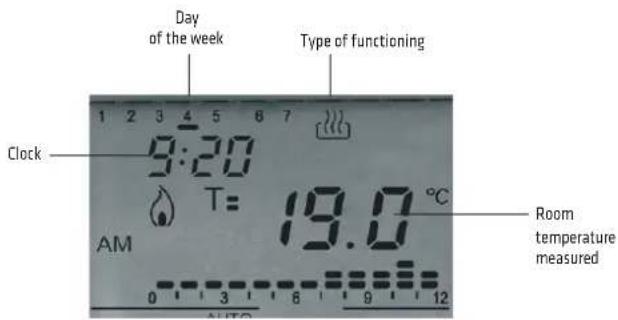
- Positive LCD display with white backlight
- Permanent indication of: time, day of the week, load lighting status, functioning/working mode status,
- 144 daily cycles that can be set (transitions every 5 minutes)
- Manual activation/deactivation of the load (MAN mode)
- Programmed activation/deactivation of the load (AUTO mode), with daily/weekly cycles
- Permanent deactivation of the load (OFF mode)
- Immediate visualisation of the daily planning, via permanently visualised histogram
- Rechargeable buffer battery
Reference standards: EN 60730-1; EN 60730-2-7

GW 20 825 - GW 21 825
Command push-buttons:
- Selection of functional mode
- Modify (increase)
- Selection of operational mode
- Modify (decrease)
| TECHNICAL DATA | |
| Power supply voltage 230V AC 50/60Hz | |
| Output contacts 1NO/NC 8A(AC1) / 4A(AC15) | 250V AC |
| Reserve charge 48 hours | |
| Dimensions 2 modules | |
| No. activations/deactivations | 144 |

Wiring terminals
Power supply: L - Phase N - Neutral
Output relay: 1 - NO contact 2 - NC contact 3 - Common
Serial line: 4 - TX (output data) 5 - GND (common) 6 - RX (input data)
Timed electronic push-button
Timer with multiple functions, equipped with push-button for local control allowing the automatic delayed switch-off of lamps, fans, extractors, etc.

Connection diagrams
Domestic and commercial sectors:
• Stairs, halls and entrance lights (diagram 1 and 2).
- Aspirator for windowless bathrooms (diagram 3 and 4).
| TECHNICAL DATA | |||
| Power supply voltage 230V - 50/60Hz | |||
| Output contacts (relays) 1NO, 10A (AC1) / 5A (AC15) - 250V AC | |||
| Tripping duration adjustment 30s / 15 min. | |||
| 1 With push-buttons 2 With push-buttons 3 With one-way switch 4 With two-way switch Possibility of resetting the delay with lamps still on. Without delay resetting Delay in stopping the aspirator after switching off the lamp(the aspirator turns on when the lamp is switched on). The timed switching on and off of the aspirator occurs after the turning off of the light. | |||
For technical information contact the Technical Assistance Service or visit gewiss.com
CLIMATE CONTROL
Timed thermostat - daily/weekly programming
The timed thermostat allows you to automatically control the weekly temperature and timing within the place of installation, together with the heating and air-conditioning systems.
- Powered by mains voltage
- Relay output contact for commanding the boiler, air-conditioner, zone solenoid valve, etc.
- LCD display with white backlight (the backlighting is activated every time one of the button-keys is pressed, and switches off 5 seconds after the last touch)
- Programming on a weekly basis (a programme for 7 days with hourly profiles independently configurable for each day)
- Setting of hourly profile on 24-hour basis, with 3 different temperature levels (T1, T2, T3) and profile display
- Programming of times with a resolution of 15 minutes without a limit in the number of daily changes
- Residual current circuit breaker for adjustment can be set and differentiated for HEATING and AIR-CONDITIONING
- PARTY and HOLIDAY functions for programming special functioning speeds of different duration periods
- Functioning modes that can be set: AUTOMATIC / MANUAL / OFF
- Possibility to select the system thermal gradient self-learning function. This function optimises the heating anticipation (up to 2 hours) in order to guarantee the set temperature right from program start;
- Rechargeable buffer battery.
Reference standards: EN 60730-1; EN 60730-2-7, EN 60730-2-9

System: GW 20 827 - GW 21 827 Playbus: GW 30 706
TECHNICAL DATA
| Power supply voltage 230V AC 50/60Hz | |
| Dimensions 2 modules | |
| Output contact 1NO/NC with potential-free contact | |
| Operating temperature -5 to +45°C | |
| Detected temperature display range 0 to +45°C | |
| Adjustment range +5 to +40°C | |
| Tolerance ±0.5°C to 20°C | |
| Reserve charge 48 hours | |

Wiring terminals
Power supply: L - Phase N - Neutral
Output relay: 1 - NO contact 2 - NC contact 3 - Common
Serial line: 4 - TX 5 - GND (common) 6 - RX
For technical information contact the Technical Assistance Service or visit gewiss.com
Wall-mounting timed thermostat - daily/weekly programming - battery-powered
The timed thermostat allows you to automatically control the weekly temperature and timing within the place of installation, together with the heating and air-conditioning systems.
- Powered with 3 alkaline batteries (1.5V AAA)
- Relay output contact for commanding the boiler, air-conditioner, zone solenoid valve, etc.
- Programming on a weekly basis (a programme with hourly profiles independently configurable for each day of the week)
- Setting of hourly profile on 24-hour basis, with 3 different temperature levels (T1, T2, T3) and profile display
- Programming of times with a resolution of 15 minutes without a limit in the number of daily changes
- Residual current circuit breaker for adjustment can be set and differentiated for HEATING and COOLING
- PARTY and HOLIDAY functions for programming special functioning speeds of different duration periods
- Functioning modes that can be set: AUTOMATIC / MANUAL / OFF
- Possibility to select the system thermal gradient self-learning function. This function optimises the heating anticipation (up to 2 hours) in order to guarantee the set temperature right from program start;
The device can be wall-mounted (fixed with plugs) or installed on a 3-module flush-mounting box.
Reference standards: EN 60730-1; EN 60730-2-7, EN 60730-2-9

GW 10 701 - GW 14 701
TECHNICAL DATA
| Power supply 3 alkaline-type batteries (1.5V AAA) | |
| Average battery life: minimum 1 year | |
| Dimensions 130 x 92 x 23mm | |
| Output contact 1NO/NC with potential-free contact | |
| 5A(AC1) / 2A(AC15) 250V AC | |
| Operating temperature -5 to +45°C | |
| Detected temperature display range 0 to +45°C | |
| Adjustment range +5 to +40°C | |
| Tolerance ± 0.5°C to 20°C | |
Base for fixing on wall with terminal block

Wiring terminals
Potential-free output: 1 - Common
2 - NO contact
3 - NC contact
Serial line: 4 - TX
5 - GND (common)
6-RX
For technical information contact the Technical Assistance Service or visit gewiss.com
Temperature control devices
Electronic summer/winter thermometer with knob adjustment

Reference standards: EN 60730-1;EN 60730-2-9
| TECHNICAL DATA | |
| Power supply voltage 230V AC - 50/60Hz | |
| Type of output | relay, with changeover contact NO/NC 8(2)A / 250V AC |
| Service connections (load) 2 or 3 wires | |
| Indicator lights | LED indicating load connected/disconnected |
| Night-time reduction control | possibility of remote application,suitable for "Winter" operation |
| Reduction temperature(referred to set temperature) | -4°C |
| Adjustment range from +5°C to +30°C | |
| Hysteresis Δ t = 0.7°C | |
| Reading accuracy ±1°C | |
| Operating temperature limits 0°C to +50°C | |
Electronic thermostat for fan coil

Reference standards: EN 60730-1;EN 60730-2-9
| TECHNICAL DATA | |
| Power supply voltage 230V AC - 50/60Hz | |
| Type of output for type of control | |
| - fixed fan | polarised single-pole three-way switch 5(2)A / 250V AC |
| - solenoid valve (thermostat-controlled): | polarised single-pole ON/OFF relay 5(2)A / 250V AC |
| - fan + solenoid valve (thermostat-controlled): | relay + three-way switch, max. total capacity 5(2)A / 250V AC |
| Indicator lights | LED indicating load connected/disconnected |
| Adjustment range from +5°C to +30°C | |
| Reading accuracy ±1°C | |
| Operating temperature limits 0°C to +50°C | |

Example of connection to boiler and clock for night-time reduction control
Installation characteristics

- Depending on the type of installation, connect the speed control wires from the fan to terminals 5 - 6 - 7:
- terminal no. 5 - fan "Fast"
- terminal no. 6 - fan "Medium"
- terminal no. 7 - fan "Slow"
• The solenoid valve command is always thermostat-controlled.
• To change the ventilation setting, follow the instructions below:
a) - Thermostat-controlled ventilation - Connect the wire emerging above the thermostat terminal block (hole 1) to terminal no. 4
b) - Fixed ventilation - Connect the wire emerging above the thermostat terminal block (hole 1) to terminal no. 3.
•The thermostat is factory-set for operation with thermostat-controlled ventilation.
For technical information contact the Technical Assistance Service or visit gewiss.com
SIGNALLING
Anti-blackout lamp
Flush-mounting anti-blackout lamp
Flush-mounting anti-blackout lamp, 1 System module, suitable for auxiliary lighting in the event of a mains failure. Front LED indicating presence of mains and standby (steady green light).

GW 20 835 - GW 21 835
| TECHNICAL DATA | |
| Power supply voltage 230V AC | |
| Battery Ni-Mh (2 elements from 2.4V) | |
| Minimum autonomy 1 hour | |
| Recharging time 12 hours | |
| Lamp White high efficiency LED | |
| Mains absorption | Max 6.5mA |
| Dimensions 1 System module | |
Extractable anti black-out lamp
Extractable lamp suitable as auxiliary lighting in the event of mains failure, with possibility to be used as flashlight. The lamp can be switched off via the frontal switch.

natural_image
White electronic device with a circular button and indicator light (no visible text or symbols)System: GW 20 833 - GW 21 833
Playbus: GW 30 501
| TECHNICAL DATA | |
| Power supply voltage 230V - 50/60Hz | |
| Batteries Ni-Mh (4.8V / 40mAh) | |
| Minimum autonomy 2h | |
| Recharging time 36 hours | |
| Lamp White high efficiency LED | |
| Mains absorption Max 6 mA | |
| Dimensions 2 System modules | |
For technical information contact the Technical Assistance Service or visit gewiss.com
Electronic ringer with 3 different sounds
Acoustic signaller with multiple functions, suitable for producing three clearly distinguished signals, e.g. bathroom alarm (emergency type sound), main entrance bell (two-tone sound), secondary entrance bell (ringing sound).
Possibility of ringer volume adjustment (using a small tool) with a selector located on the front of the product.

| TECHNICAL DATA | |
| Power supply voltage | GW 20 641 - GW 21 641 12V 50HzGW 20 643 - GW 21 643 230V 50Hz |
| Sound intensity | GW 20 641 - GW 21 641 90dB at 1mGW 20 643 - GW 21 643 90dB at 1m |
| Max. power absorbed | GW 20 641 - GW 21 641 3 VAGW 20 643 - GW 21 643 3 VA |
Application examples
bathroom alarm bell terminal 1 (emergency)
main entrance bell terminal 2 (two-tone)
secondary entrance bell terminal 3 (ring)


Stair riser lamp with white LED 12-230V AC
The product has a dual power supply input (12 - 230V AC), a light beam adjuster device, and an integrated white LED.
Reference standards: EN 62094-1

natural_image
Blank white rectangular object with a transparent base, no visible text or symbolsCW 20 634 GW 21 634
| TECHNICAL DATA | |
| Power supply voltage 12/230V AC double input | |
| Type of lamp Bright white LED | |
| Draw | 12V 0.12 W/0.12 VA230V 0.6 W/3.6 VA |

For technical information contact the Technical Assistance Service or visit gewiss.com
SAFETY
Gas detectors
The gas detectors reveal the presence of substances (CH₄/GPL) that are dangerous for the domestic environment where they are installed
- Indicator lights and acoustic alarm signalling
- Closure of a solenoid valve, via relay
- Indicator lights for malfunctioning of sensor or device
- Device operating test function
The closure of the solenoid valve via the relay is carried out approximately 20s after the start of the alarm situation.
The push-button allows you to carry out the operational test: when pressed, the red LED lights up (alarm signalling), the buzzer sounds and, after about 20s, the relay is activated. Upon the release of the push-button, the signalling is immediately deactivated.
The detectors can be powered through the 12V power supply unit GW10720.
Owing to the particular thermal sensitivity of the LPG sensor, you are advised to position it far from the power supply unit, and apply a blanking module.
Reference standards: EN 50081-1; EN 50082-1

LPG
System: GW 20 868 - GW 21 868
Playbus: GW 30 520
METHANE GAS
System: GW 20 867 - GW 21 867
Playbus: CW 30 519
Connection terminals
L-N - 12V AC/DC power supply
1 - Common
2 - NC contact
3 - NO contact
4 - NO contact
TECHNICAL DATA
| Power supply voltage 12V AC/DC | |
| Power absorbed 2 VA | |
| Alarm threshold 9% LIE (lower explosive limit) | |
| Alarm sound level 85 dB at 1m | |
| Operating temperature +5 to +40°C | |
| Relative environmental humidity +30 to +90% without condensation | |
| Output contact in switching: 1 NO/NC 10A (NO)/3A (NC) 250V AC | |
| Fixing flush-mounting on CHORUS support | |
| Dimensions 2 modules | |
| Lifespan of device 5 years from when first powered | |
Connection diagram

Correct positioning of detectors

LPG gas

12Vdc power supply unit
Insulation transformer suitable for the power supply of gas (methane and LPG) detectors. Internally protected against overloading, short-circuiting and excessively high temperatures.
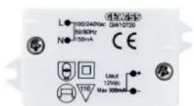
GW 10 720
Wiring terminals
Power supply:
L - Phase
N - Neutral
12V output:
+12V - Positive
-12V - Negative
TECHNICAL DATA
| Power supply voltage | 110/240Vac - 50/60Hz - 150mA |
| Output voltage | 12V dc - 300mA |
| Dimensions (mm) | 52x33x17 |
For technical information contact the Technical Assistance Service or visit gewiss.com
HOTEL COMPONENTS
"Do not disturb" and "Make up the room" command and light signalling
Inside the hotel room is located a 3-way switch with printed the symbols "Do not disturb" and "Make up the room". It is used to inform the service staff, thanks to an external double indicator lamp unit, the customer's will not be disturbed or to clean the room.

Three-way switch 1P - 10AX
DND + MUR
GW 20 651

230V indicator lamp unit
DND + MUR
GW 20 656
The indicator lamp unit is supplied with 230V LED lamps (red for DND signalling, green for MUR signalling)
Application example

For technical information contact the Technical Assistance Service or visit gewiss.com
- General characteristics
- Common construction features
- Degree of protection of the set of SYSTEM domestic range assembly installed
- ACCESSORIES
- Spare parts and accessories
- Lamps for System articles
- Examples of functional and localisation lighting
- To indicate the operating status of services not visible from the command position
- To locate the command button key in the dark
- COMMAND
- Infrared movement detector
- Relay
- Latching relay
- Momentary relay
- Call relay
- "Bathroom Alarm" call system
- Multiple call system
- SIGNAL
- TV-SAT socket-outlets
- Telephone connectors
- Diagrams
- Connectors for structured wiring
- Quick wiring system
- Adapters for structured wiring
- USB and HDMI couplers
- USB charger
- PROTECTION
- Protection devices
- Overvoltage limiter
- Automatic circuit breakers
- DIMMER
- Rotating electronic regulators, for resistive/inductive loads
- Typical use:
- WARNINGS
- Rotating electronic regulators with two-way switch, for resistive/inductive loads
- Push-button electronic regulators, for air agitators
- Technical data
- Push-button electronic regulators, for resistive/inductive loads
- ENERGY AND COMFORT MANAGEMENT
- 1-channel daily and weekly electronic timer
- Wiring terminals
- Timed electronic push-button
- Connection diagrams
- CLIMATE CONTROL
- Timed thermostat - daily/weekly programming
- Wall-mounting timed thermostat - daily/weekly programming - battery-powered
- Temperature control devices
- Electronic summer/winter thermometer with knob adjustment
- Electronic thermostat for fan coil
- Installation characteristics
- SIGNALLING
- Anti-blackout lamp
- Flush-mounting anti-blackout lamp
- Extractable anti black-out lamp
- Electronic ringer with 3 different sounds
- Application examples
- Stair riser lamp with white LED 12-230V AC
- SAFETY
- Gas detectors
- Connection terminals
- 12Vdc power supply unit
- Power supply:
- 12V output:
- HOTEL COMPONENTS
- "Do not disturb" and "Make up the room" command and light signalling
Brand : Gewiss
Model : GW21606
Category : Electrical Modular System