
THH 1800A - Heating Heatstrip - Free user manual and instructions
Find the device manual for free THH 1800A Heatstrip in PDF.

| Product Type | High intensity electric radiant overhead heater |
| Model | THH 1800A |
| Dimensions (mm) | 1104 x 165 x 48 |
| Weight (kg) | 6 |
| Power Supply | 230-240 V, 50-60 Hz, single phase |
| Power Consumption (W) | 1800 |
| Current (A) | 7.5 |
| Lead Length (mm) | 1000 |
| Plug Type | Yes (supplied) |
| Heating Element | Profiled alloy |
| Ideal Mounting Height (m) | 2.3 - 2.5 |
| Minimum Mounting Height (m) | 2.1 |
| Maximum Mounting Height (m) | 2.7 (fully enclosed outdoor) |
| Protection Rating | IP55 |
| Housing Material | Black face, anodised alloy rear casing |
| Warranty | 24 months residential, 12 months commercial |
| Country of Manufacture | Australia |
| Cleaning | Hose down with mild detergent; rinse; do not use abrasives |
| Safety | Surface is very hot; allow 30 min to cool; keep combustibles away |
| Repairability | Return to point of purchase for repair by Thermofilm |
Frequently Asked Questions - THH 1800A Heatstrip
User questions about THH 1800A Heatstrip
0 question about this device. Answer the ones you know or ask your own.
Ask a new question about this device
Download the instructions for your Heating in PDF format for free! Find your manual THH 1800A - Heatstrip and take your electronic device back in hand. On this page are published all the documents necessary for the use of your device. THH 1800A by Heatstrip.
USER MANUAL THH 1800A Heatstrip
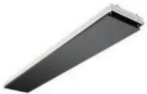
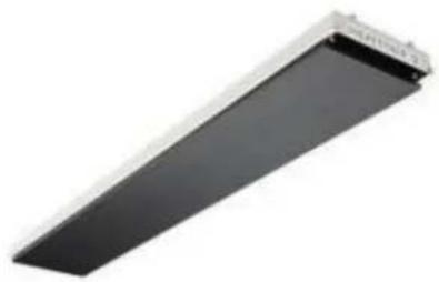
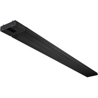
HEATSTRIP ® Classic (THH-A)
The heater that is a design fea ture!
Product Overview
Rev N JUN18
There are 5 different ranges within the electric HEATSTRIP product category. Each has a different temperature rating making them suited to a variety of applications. Below is a list of some common applications, to assist with the selection of the most effective and efficient series. This is a general guide only, please refer to the Product Manual for each product, for more information.
HEATSTRIP ® Indoor (THS-A models) is a medium intensity heater used for protected indoor applications only with installation heights up to 2.5m (THS800A) or 2.7m (all other THS-A models).
HEATSTRIP® Classic (THH-A models) is a premium high temperature heater and is primarily used for protected outdoor areas with an ideal mounting height of 2.3m to 2.5m and maximum mounting height of 2.7m.
HEATSTRIP® Elegance (THE models) is a premium high temperature heater and is primarily used for protected outdoor areas with an ideal mounting height of 2.3m to 2.5m and maximum mounting height of 2.7m.
HEATSTRIP® Max (THX models) is an ultra high temperature heater used for uncovered or open indoor or outdoor areas with an ideal mounting height of 2.3 m to 2.7 m, and up to a maximum 3.5 m for protected indoor applications.
HEATSTRIP® Intense (THY models) is an instant high temperature heater perfect for any exposed outdoor or indoor areas with an ideal mounting height of 2.3m to 2.8m, and a maximum of 3m in an outdoor exposed application.
| APPLICATION THS | THHTHE | THX | THY | |
| Indoor insulated areas: classrooms, offices, bathrooms, wet areas, drying rooms | √ √ | √ | ||
| Outdoor under cover: café, veranda, patio, balcony ceiling height 2.7m or less | √ √ √ | |||
| Outdoor under cover: café, veranda, patio, balcony ceiling height 2.7m or more | √ | |||
| Highly exposed outdoor area | √ √ | |||
| Indoor open area: warehouse, factory, production areas, sports facilities | √ √ √ √ | |||
| Indoor spot heating, above tables, assembly areas | √ √ √ | |||

Efficient, cost effective electric heating
The innovative design of the HEATSTRIP® enables comfortable and even heat dispersion from the surface with minimal operating costs.
Design flexibility
Four HEATSTRIP ® models are available, ensuring the heating requirements of any undercover outdoor or open indoor area is possible. Brackets for direct ceiling or wall/ceiling angled mounting are supplied as standard. Optional HEATSTRIP ® accessories include beam or fixed umbrella mount brackets, extension mount brackets, chain suspension brackets, twin mount brackets and flush mounting enclosures.
Minimal maintenance
The HEATSTRIP® incorporates no internal moving parts ensuring quiet and virtually maintenance free operation.
Australian made
Designed, engineered and assembled in Australia the HEATSTRIP ® , is fully backed by a 24 month residential warranty, and 12 month commercial warranty.
Stylish design— The Heater that is a Design Feature!
The attractive HEATSTRIP ® comes with a standard black face and anodised alloy rear casing.
Easy to use
The standard HEATSTRIP® is controller by a simple on/off operation, either when plugged directly into a power point, or hard-wired via a wall mounted on/off switch. The unit takes approximately 15 minutes to heat up to maximum temperature and approximately 30 minutes to cool down, depending upon the ambient temperature. Please don't forget to turn it off. We recommend installing your HEATSTRIP® Classic with a timer controller to ensure the unit is turned off after a preset time. Thermofilm recommends Model TT-MTM controller, which includes a timer function and temperature control.
Why choose HEATSTRIP® electric radiant heaters for your outdoor or hard-to-heat indoor area?
Many conventional patio heaters rely on convection heating which works by heating the surrounding air to provide comfort. This can be quite impractical for outdoor and open-indoor areas as there is typically constant air movement which can easily blow away the warmed air. Radiant style heaters transfer heat directly to objects through infra-red waves.
While convection heaters heat the air between objects, radiant heaters directly heat the surface of the objects themselves.
HEATSTRIP ® electric radiant heaters are more effective within an outdoor or uninsulated indoor area because they provide targeted warmth directly to the people and objects in their path.
Discrete, stylish heating for undercover outdoor and indoor open areas
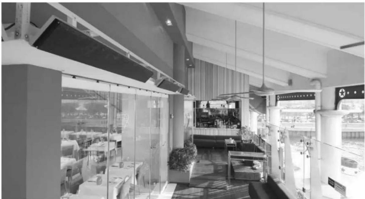
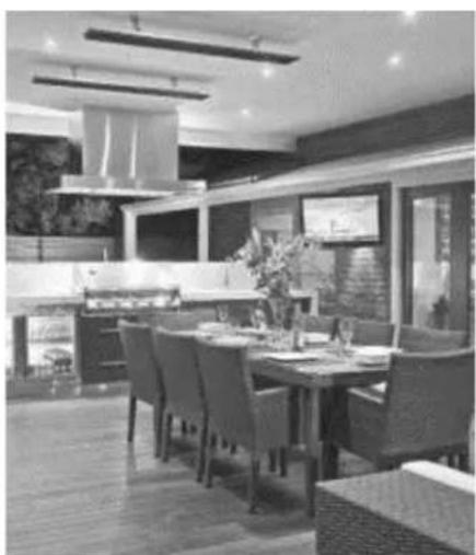
Using the radiant heating principle, HEATSTRIP ® can provide effective and energy efficient comfort heating for undercover outdoor and indoor open areas. HEATSTRIP ® has successfully enabled many entertainment venues such as restaurants, pubs and clubs to utilise their outdoor dining areas day and night, through all seasons. Within your workplace or business, HEATSTRIP ® can provide comfort heating for designated outdoor smoking and leisure areas, as well as for workstation spot heating in factories, warehouses and showrooms. Within your home, HEATSTRIP ® can provide comfort heating for undercover alfresco dining and BBQ area, patios, verandas, courtyards and balconies.
Subtle, minimalist design
The stylish, slimline black face of the HEATSTRIP ® does not emit light or glow when in use, blending elegantly into your décor. Ceiling, wall and umbrella mounting options ensure that your valuable floor and table space is not wasted.
Efficient, cost effective electric heating
The innovative design of the HEATSTRIP ® enables comfortable and even heat dispersion from the heater surface with minimal operating costs.
Design flexibility
Four HEATSTRIP ® models are available, ensuring the heating requirements of any undercover outdoor or open indoor area is possible. Brackets for direct ceiling or wall/ceiling angled mounting are supplied as standard.
Optional HEATSTRIP ® accessories include beam or fixed umbrella mount brackets, extension mount brackets,
chain suspension brackets, twin mount brackets and flush mounting enclosures.
Minimal maintenance
The HEATSTRIP ® incorporates no internal moving parts ensuring quiet and virtually maintenance free operation.
Australian Product
Designed, engineered and assembled in Australia the HEATSTRIP® Classic is fully backed by a 24 month residential warranty, and 12 month commercial warranty.
Stylish design— The Heater that is a Design Feature!
The attractive HEATSTRIP ® comes with a standard black face and anodised alloy rear casing.
Easy to use
The standard HEATSTRIP® Classic is controlled by a simple on/off operation, either when plugged directly into a power point, or hard-wired via a wall mounted on/off switch. The unit takes approximately 15 minutes to heat up to maximum temperature and approximately 30 minutes to cool down, depending upon the ambient temperature. Please don't forget to turn it off.
We recommend installing your HEATSTRIP ® with a timer controller to ensure the unit is turned off after a pre-set time. Thermofilm recommends Model TT-MTM controller, which includes a timer function and temperature control functions.
Specifications - Australia
| MODEL POWER (WATTS) | CURRENT (AMPS) | DIMENSIONS (mm) | WEIGHT (Kg) | LEAD LENGTH (mm) | PLUG | |
| THH1800A | 1800 | 7.5 | 1104x 165 x 48 | 6 | 1000 | YES |
| THH2400A | 2400 | 10 | 1364 x 165 x 48 | 7 | 1000 | YES |
| THH3200A | 3200 | 13.3 | 1774 x 165 x 48 | 9 | 500 | NO |
MODEL
| HEATER TYPE | High intensity electric radiant overhead heater with high surface area profiled alloy | |
| OUTPUT | Refer to model code chart above | |
| POWER | 230-240 Volts Nominal at 50—60 Hertz, Single Phase | |
| CONNECTION | 3 Core Cable 2.5mm2 | |
| APPROVALS | AUSTRALIA/NZ | |
| MOUNTING HEIGHT | MINIMUM RECOMMENDED MAXIMUM | 2.1 m2.3 m to 2.5 m2.7 m in a fully enclosed outdoor area (For higher ceiling heights, units can be lowered using optional bracket kits or refer to the Heatstrip Max range) |
| MOUNTING OPTIONS | Suitable for ceiling, wall, beam, fixed umbrella and recess mounting. Also available for extension mount using rigid fixing poles and chain mount bracket. | |
| PROTECTION RATING | IP55 Protection from water ingress from all directions | |
| COUNTRY OF MANUFACTURE Australia | ||

Specifications - International
HEATSTRIP ® is supplied to many international markets, and therefore is available in a range of voltages and lead configurations to meet local market approvals. HEATSTRIP ® is fully compliant to the following international standards.
Europe CE, ROHS, IEC 60335-2-30:2002
USA/Canada UL/CSA E321442
Japan PSE
| MODEL REGION VOLTAGE(Volts) | POWER(WATTS) | CURRENT(AMPS) | DIMENSIONS(mm) | WEIGHT(Kg) | LEADLENGTH(mm) | PLUG | ||
| THH1500AEU | EUROPE | 230 | 1500 | 6.3 | 924 x 165 x 48 | 5 | 1000 | YES230V |
| THH2400AEU | EUROPE | 230 | 2400 | 10 | 1364 x 165 x 48 | 7 | 1000 | YES230V |
| THH3200AEU | EUROPE | 230 | 3200 | 13.3 | 1774 x 165 x 48 | 8 | 500 | NO |
| THH1500AUK | UNITED KINGDOM | 240 | 1500 | 6.3 | 924 x 165 x 48 | 5 | 1000 | YES240V |
| THH2400AUK | UNITED KINGDOM | 240 | 2400 | 10 | 1364 x 165 x 48 | 7 | 1000 | YES240V |
| THH3200AUK | UNITED KINGDOM | 240 | 3200 | 13.3 | 1774 x 165 x 48 | 8 | 500 | NO |
| THH1500AUL | NORTH AMERICA | 115 1500 | 6.3 | 924 x 165 x 115 | 5 | NONE | NO | |
| THH2400AUL | NORTH AMERICA | 240 | 2400 | 10 | 924 x 165 x 115 | 7 | NONE | NO |
| THH3200AUL | NORTH AMERICA | 240 | 3200 | 13.3 | 924 x 165 x 115 | 9 | NONE | NO |
| THH2400AUM | NORTH AMERICA | 208 | 2400 | 10 | 924 x 165 x 115 | 7 | NONE | NO |
| THH3200AUM | NORTH AMERICA | 208 | 3200 | 13.3 | 924 x 165 x 115 | 9 | NONE | NO |
| THH1300AJP | JAPAN | 100 | 1300 | 6.3 | 924 x 165 x 48 | 5 | 1000 | YES100V |
| THH1400AJP | JAPAN | 200 | 1400 | 7.5 | 924 x 165 x 48 | 5 | 1000 | YES200V |
| THH1600AJP | JAPAN | 200 | 1600 | 10 | 1104x 165 x 48 | 6 | 1000 | YES200V |
Operating cost comparison
In many instances, patio heaters powered by gas bottles are used as an outdoor heating source. The below table shows the operational cost comparison between HEATSTRIP® and a bottled gas outdoor heater. Not only are the hourly running costs considerably less with HEATSTRIP®, but you never have to worry about running out of gas, no refilling, no unattractive gas bottle to waste space; and HEATSTRIP® actually improves the value of your property.
| RUNNING COST | OUTDOOR GAS HEATER | HEATSTRIP® CLASSIC ELECTRIC RADIANT HEATER | ||
| THH1800A THH2400A THH3200A | ||||
| PER HOUR | 2.78/hr | 0.36/hr | 0.48/hr | 0.64/hr |
| PER YEAR | 500.40 | 64.80 | 86.40 | 115.20 |
Notes:
- Calculations of hourly running cost for outdoor gas heater is based on \25.00 average to fill a 9kg gas bottle and average running time of 9 hours. \25.00 / 9 hours = \$2.78 per hour
- Electricity rate of 20.0 cents/kWh
- All calculations are excluding GST.
1.8kW x 0.20 cents = \$0.36 or 36 cents per hour
2.4kW x 0.20 cents = \$0.48 or 48 cents per hour
3.2kW x 0.20 cents = \$0.64 or 64 cents per hour
Calculations of yearly running cost are based on 180 hours usage
180 hours x \2.78 = \500.40 yearly running cost for outdoor gas heater
180 hours x \0.36 = \64.80 yearly running cost for 1800W HEATSTRIP®
180 hours x \0.48 = \86.40 yearly running cost for 2400W HEATSTRIP ®
180 hours x \0.64 cents = \115.20 yearly running cost for 3200W HEATSTRIP®
Spot heating principle
In most outdoor or difficult-to-heat indoor applications, there are 2 options when looking at the size and quantity of the heaters required.
Option 1 is to comfort heat the entire area based on the total dimensions of the space, regardless of whether the entire area is being fully occupied.
Option 2 is to spot heat the high use areas, such as over outdoor tables, BBQ's, lounges, assembly lines or indoor workstations.
Often it is more practical and efficient to spot heat high use areas. Spot heating will reduce both the initial capital cost as well as the ongoing running costs. Spot heating will allow the area to be “zoned”, meaning only the areas that are being used are heated, such as tables in a restaurant or outdoor alfresco area.
Option 1 and 2 show a comparison between heating an entire area or spot heating over a table.
The bottom layout shows the flexibility of using HEATSTRIP ® to provide a comfortable environment, even when the layout of the area is very unusual.

Option 1: 6 x THH2400A Option 2: 2 x THH2400A


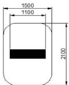
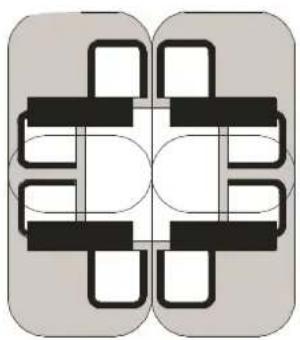
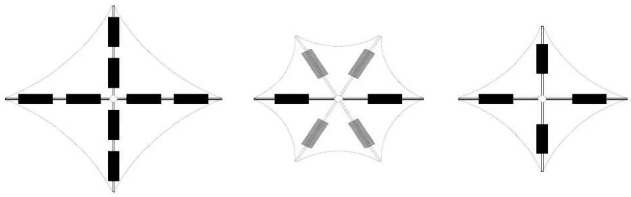
Radiant footprint
HEATSTRIP® electric heaters produce radiant heat which heats objects rather than the air. Therefore, it is imperative that
objects to be heated (ie. people), are within the direct radiant footprint of the heater.
The diagram to the left shows the radiant footprint of HEATSTRIP® Classic, and is an approximate guide based on a fully enclosed outdoor environment.
This diagram shows that the maximum heat output is found directly under the heater, and the temperature decreases as you move away from the heater.
It highlights the importance of maintaining recommended mounting heights, and if possible, positioning the heater directly above the area to be heated.
Note that the temperature is the same for all 4 models, regardless of the wattage.
However, as the size increases and the length of the unit increases, the radiant footprint will be longer.

The below diagrams show the approximate heating area for each model, based on both an indoor and outdoor enclosed environment, with direct overhead mounting.
The radiant footprint is reduced in angled, wall mounted installations.
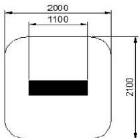
THH1800
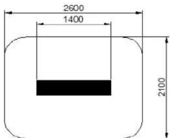
THH2400
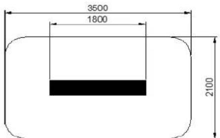
THH3200
THH1800

THH2400

THH3200
Selection guide
General recommendations for HEATSTRIP® Classic:
- Ideal mounting height: 2.3m to 2.5m. Maximum is 2.7m in a fully protected/enclosed outdoor environment.
- Ideal mounting location: ceiling mounted, directly above area to be heated (eg. above a table)
- Based on the radiant footprint of the previous page, for a protected outdoor area, a minimum of 500W/m 2 is required. For indoor spot heating, a minimum heating capacity of 400W/m 2 is recommended.
The table below outlines the coverage of each HEATSTRIP® Classic model based on 3 different scenarios with direct overhead mounting. For example, for an outdoor area that is protected from prevailing winds by walls, café blinds etc, Model THH 1500A will cover 3m2 and Model THH2400A will cover 4.8m2 .
For angled wall mounting applications, the coverage is reduced by up to 40%.
| MODEL INDOOR PROTECTED (m 2 ) OUTDOOR ENCLOSED (m 2 ) OUTDOOR EXPOSED (m 2 ) | |||
| THH 1800A | 4.5 | 3.6 | 3 |
| THH 2400A | 6 | 4.8 | 4 |
| THH 3200A | 8 | 6.4 | 5.3 |

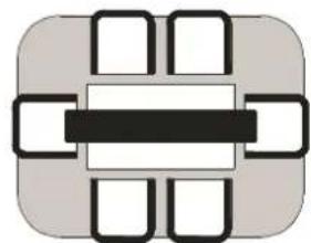
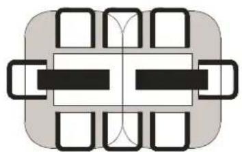
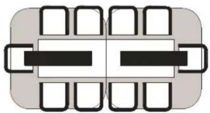
Table layout
For the majority of outdoor applications, the most effective method is to spot heat a table or similar area. The diagrams below provide an easy selection guide for the approximate model and quantity of heaters required to heat common residential table settings.
Selections are based on HEATSTRIP® Classic being mounted at 2.4m from the floor in a fully enclosed undercover outdoor area.

THH2400
THH3200

THH3200
2 x THH1800

2 x THH1800
2 x THH2400
4 x THH1800

2 x THH3200
Installation Requirements
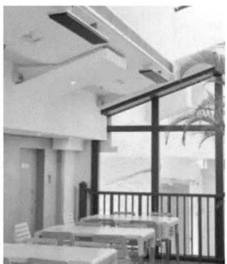
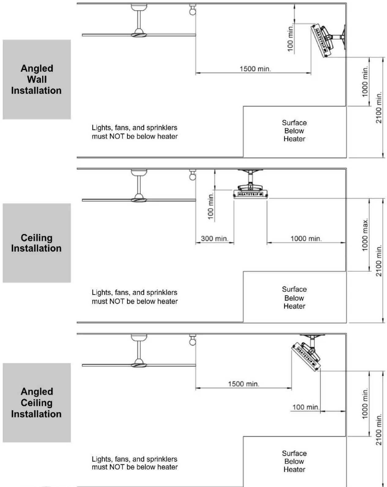
The ideal mounting position for the HEATSTRIP® Classic is on the ceiling directly above the area to be heated. If this is not possible, HEATSTRIP® can be mounted on a wall and angled downwards. In this situation, ensure the mounting height is in the range of 2.1m to 2.7m and the table is within 2.5m of the wall.
For mounting heights more than 2.7m, we recommend the use of the optional accessories to reduce the height of the heater to 2.3m—2.5 m. This will increase the effectiveness of your HEATSTRIP ® . Refer to the Mounting Accessory section for more information.
Electrical connections/GPO's should not be located at the back of the heater. They should be located outside the physical footprint of the units to minimize heat build-up behind the units. If the heater is to be mounted on an incline (e.g. vaulted ceiling), ensure the electrical connection is located at the lowest point of the heater.
| Incorrect Installation Correct Installation | |
 |  |
 |  |
 The heating surface must levelbe directed toward the ceiling The heating surface must levelbe directed toward the ceiling | |
Installation location — the diagrams below provide the minimum recommended clearances in mm.
WARNING: This heater is not equipped with a device to control the room temperature. Do not use this heater in small rooms when they are occupied by persons not capable of leaving the room on their own, unless constant supervision is provided.
Mounting options
Installing the HEATSTRIP® Classic is simple and easy using the standard mounting brackets supplied. For other irregular locations there are range of mounting options available - refer to diagrams below
The HEATSTRIP® Classic can be mounted directly to the ceiling, angled downwards on a wall, fitted flush with the ceiling, suspended on chains or poles, attached to beams or poles, mounted end-to-end, or 2 units side-by-side together. Refer to the following pages for more detailed information on each mounting option.

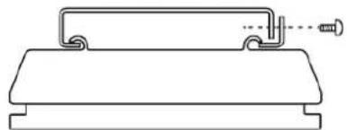
Standard mounting brackets
The HEATSTRIP ® Classic comes with a pair of standard mounting brackets. These adjustable brackets allow direct ceiling or wall mount, and come with preset angle options of parallel, 22.5° and 45°.

Flush mount enclosure
The Flush Mount Enclosure is an ideal way to neatly install the HEATSTRIP ® into a ceiling. They are available for all HEATSTRIP ® Classic models, and are supplied as a one-piece unit suitable for mounting individual heaters. Flush mounting can be used with plaster or timber lined ceiling materials.
An ideal mounting height is 2.3m-2.5m, with a maximum ceiling height of 2.7m in an outdoor enclosed environment. Maximum mounting heights should be strictly followed, otherwise the performance of the units may be reduced.
The facia of the enclosure is manufactured from 316 Stainless Steel and the rear casing is black zinc coated steel.
Please refer to the Flush Mount Enclosure Installation Manual for more detailed installation information.
| SUITABLE FOR MODELS | PART No | HOLE CUTOUT DIMENSIONS (mm) | OVERALL DIMENSIONS (mm) | WEIGHT (kg) |
| THH 1800A | THHAC-010 | 1160 x 230 | 1210 x 280 x 125 | 6 |
| THH 2400A | THHAC-011 | 1420 x 230 | 1470 x 280 x 125 | 8 |
| THH 3200A | THHAC-012 | 1830 x 230 | 1880 x 280 x 125 | 9 |

Mounting bracket detail
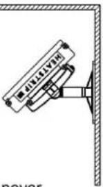
HEATSTRIP Wall Mounting Kit - (THHAC-028)
HEATSTRIP Wall Mounting Kit is an ideal way to install units into hard to mount applications where wall mounting is preferable to direct overhead mounting, applications include heating over tables, lounges, work stations etc. These kits are suitable for all HEATSTRIP Elegance & Classic models.
Instructions:
Fix the wall bracket in the desired location using 6 x 8 mm fasteners that will be more than adequate to safely support the bracket and the HEATSTRIP unit.
When bracket is installed lift the heater into position passing the power cord through the hole. Locate the heater so the L bracket fits into the mounting grove located on the back of the HEATSTRIP.
Position the angle piece into the mounting grove on opposite side of the heater and secure firmly onto the bracket using the 3 screws provided.

Installation Location - The below diagram outlines the recommended clearances.
Note: The minimum height from the ground to bottom of the bracket is 2.1m, and the maximum height from the ground to the end of the heater is 2.7m. We recommend a mounting height of 2.3 to 2.5m.

FLOOR
| DIMENSION (mm) WEIGHT (Kg) MATERIALS | ||
| 550 (L) x 165 (W) x 250 (H) | 3.5 | Powder coated Mild Steel |
Suspension mount bracket
If the space to be heated is an enclosed outdoor environment with a ceiling height of 2.7m or more, it is recommended to lower the heaters to an ideal mounting height of 2.3m—2.5m. The Suspension Mount bracket provides a cheap, easy and effective option for lowering the HEATSTRIP ® Classic from high ceilings. The bracket is designed to be used with chains or wires. There can be multiple chain/wire arrangement options, as per the diagram below.
Note: chains or cable are not supplied with heaters or brackets.
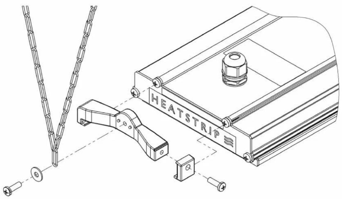
Chain / Wire Suspension Mount
| SUITABLE FOR MODELS | PART No | PACKAGED DIMENSIONS (mm) | WEIGHT (kg) | MATERIALS |
| THH 1800A | THHAC-002 | 300 x 150 x 50 | 1 | 316 SS |
| THH 2400A THH 3200A | THHAC-003 | 1200 x 120 x 50 | 2 | 316 SS |
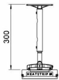
Extension Mount Bracket
The Extension Mount bracket allows HEATSTRIP® Classic units to be lowered from high ceilings using rigid connections. The brackets are designed to be used with 25mm x 25mm x 1mm tube (SHS), and can be supplied as brackets only for customising the length of the drop on site, or supplied as a complete kit with brackets, pre-cut poles and connections. The standard length options as part of the kit are 150mm, 300mm, 600mm, 900mm and 1200mm.
The kits include all brackets, poles and screws necessary for connection to the heaters, however it does not include screws for attachment to the ceiling.
* screws to ceiling are not included


Standard Bracket

| PART No | PACKAGED DIMENSIONS (mm) | WEIGHT (kg) | MATERIALS | NOTES |
| THHAC-005 | 300 x 150 x 50 | 0.21 | ALLOY | Kit includes 2x300mm extension pole, screws & brackets |
| THHAC-006 | 600 x 150 x 50 | 0.38 | ALLOY | Kit includes 2x600mm extension pole, screws & brackets |
| THHAC-007 | 900 x 150 x 50 | 0.55 | ALLOY | Kit includes 2x900mm extension pole, screws & brackets |
| THHAC-008 | 1200 x 150 x 50 | 0.71 | ALLOY | Kit includes 2x1200mm extension pole, screws & brackets |
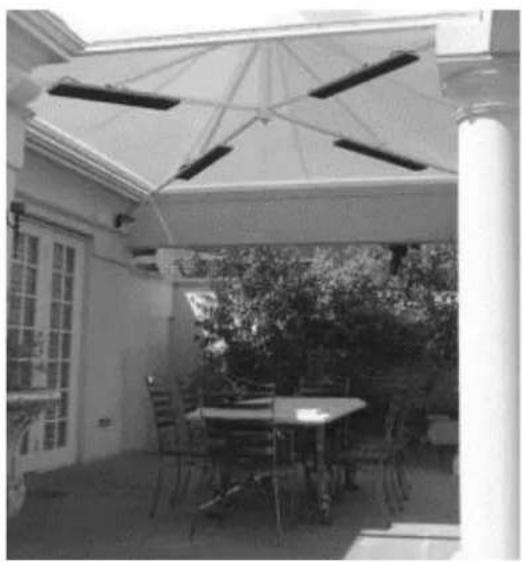
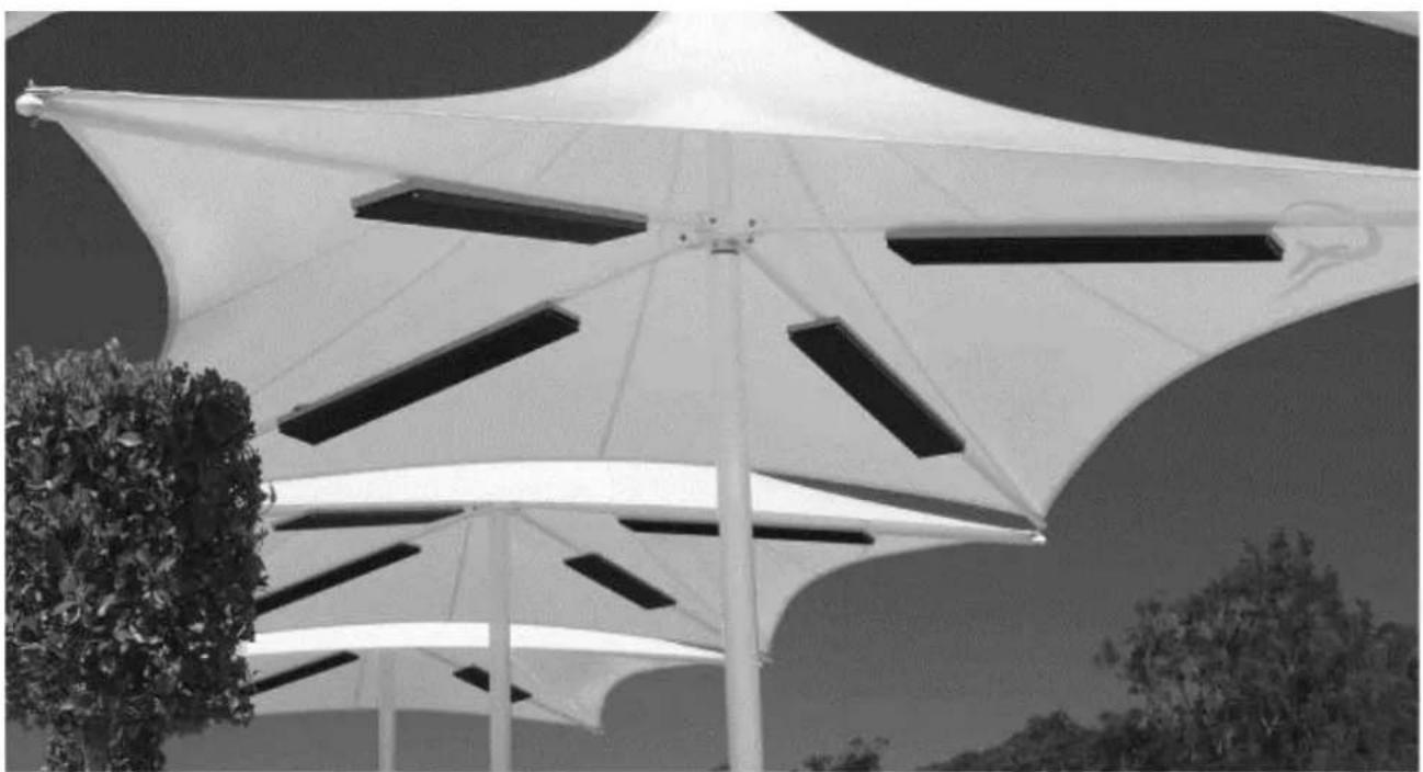
Permanent Umbrella Mounting Guide
HEATSTRIP® Classic heaters can be mounted underneath most commercial grade, permanent umbrella's or shade structures. The material must protect the heater from direct rainfall. All models can be connected to the horizontal umbrellas struts, using the Pole/Beam mounting kit (THHAC-001).
Quick reference guide for spot heating common permanent umbrella structure:
12 m2 umbrella area 6 x THH 1500A or 4 x THH 1800A
16 m2 umbrella area 8 x THH 1500A or 6 x THH 1800A
This is a guide only. For more detailed information, please contact the umbrella manufacturer, your nearest HEATSTRIP retailer or Thermofilm.
Safety
HEATSTRIP® Classic has an IP rating of 55. This means it is safe for water ingress from all directions. The HEATSTRIP® can be safely hosed down.
HEATSTRIP ® has undergone extensive testing both in laboratory conditions, in Thermofilm's manufacturing facility in Melbourne and field trials in Australia and overseas. It is this testing that gives the purchaser the confidence of a high quality product.
Independent laboratory testing has confirmed Thermofilm's full compliance with Australian and other International Standards including CE, AS/ANZ, UL/CSA
The heater comes in both plug (1500W, 1800W, 2400W) and hardwired (3200W) versions. In both cases the fixed wiring must be installed by a licensed electrician in accordance with the relevant wiring regulations.
HEATSTRIP ® is Class 1 equipment and must be earthed.
In operation, this heater is VERY HOT—do not touch any part of the heater while it is turned on. Do not touch any part until 30 minutes after it is turned off.
This appliance is not intended for use by persons (including children) with reduced physical, sensory or intellectual capabilities, or lack of experience and knowledge, unless they have been given supervision or instruction concerning use of the appliance by a person responsible for their safety. Children should be supervised to ensure they do not play with the appliance.
Do not allow any cables, furnishings, flammable materials or other items come in contact with any surface of the heater.
If installed in wet areas, the heater switches or controls must be located so that they cannot be touched by persons in the bath or shower.
The heater needs to be installed as per the installation instructions paying special attention to the minimum clearances. The heater needs to be mounted on a rigid bracket or fixing.
The heater must not be mounted immediately below or in front of a socket outlet.
In case of a heater fault or damaged supply lead, the appliance should be returned to the point of purchase for return to Thermofilm for repair.
Maintenance
The HEATSTRIP ® Classic is made from durable materials, however regular care and maintenance of your heater will help prolong the life of the heater.
It is recommended that you hose down the heater and with a soft cloth gently wipe the surfaces of the heater with a mild detergent to remove the built up contaminants from the environment. Then rinse all detergent off the heater.
All chemicals in the atmosphere including cigarette smoke, pollution etc. will tarnish the surface of the heater. In this case, additional cleaning and maintenance may be required. Carrying out the cleaning process at least every three months will reduce the amount of build up and keep the Heatstrip in good condition. If the heater is in a corrosive environment eg. salt spray, we recommend that you clean your heater with a light spray of fresh water every week. After cleaning, turn the heater on for 20 minutes to dry any water residue and prevent water staining.
Before cleaning or inspection activity, the heater must be switched off and cooled down completely.
Do not use any abrasive materials or products to clean the heater, this includes solvents, citrus based cleaners or other harsh cleaning products.
When handling the heater, ensure that your hands are clean or that you use clean gloves as grease or dirt can mark the surface of the heater.
Do not use high pressure water to clean heaters, light water spray only.
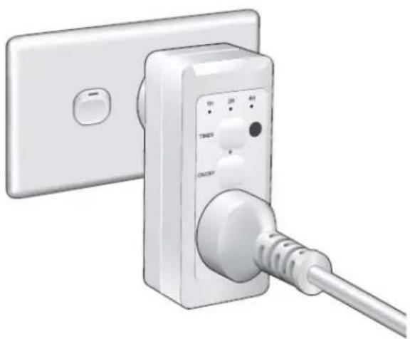
HEATSTRIP Plug In Remote Controller
The TT-MTR-PLUG has been designed to provide easy remote control timer functionality to wall socket powered HEATSTRIP® heaters. The unit can however be used to remotely operate with timer functionality any device powered by a standard 10A Australian wall socket outlet.
The TT-MTR-PLUG controller consists of a remote control and a plug-in wall socket timer unit to provide easy wireless timer operation.
Design Features
- The TT-MTR-PLUG provides an easy means of remotely turning on appliances that are normally permanently connected to a standard wall socket.
- An easily selected 1 hour, 2 hour and 4 hour timer function accessible on both the wall unit and remote
- Programmable remote control unit capable of controlling multiple units.
Specifications:
| Remote battery CR2025, 3V, | Lithium |
| Remote range 10m | |
| Wall socket supply 220V — 240V, 50Hz | |
| Max load 10A (2400W) | |
| Standby consumption <1W | |
| Remote frequency 38kHz IR | |
| Approvals Australian Standards AS/NZ3105, 3112, 3100 | |
| Packaged dimensions 140 x 65 x 67 | |
| Unit weight | |

HEATSTRIP® Wall Controller with Remote
The HEATSTRIP ® Classic can be controlled via a simple on/off wall mounted switch, however it is recommended to use a controller with a variable heat modulator and a timer, to give the best performance and lowest running cost.
TT-MTM Wall Controller
This controller is a custom designed and manufactured controller for HEATSTRIP® heaters. It has been designed for ease of use and to provide low running costs of your heater. It provides both temperature control (allowing the user to turn the heat output up or down depending on the ambient temperature and conditions) and a timer for automatic heater shut-off operation.
The timer function has four settings: 1 hour, 2 hours, 4 hours or constantly on. This feature is ideal for applications such as BBQ, alfresco areas, restaurant dining, assembly line production etc. when continuous heat is not required. The timer also reduces the likelihood of heaters being inadvertently left turned on.
Depending on the ambient temperature there may be a requirement to adjust the heat output of the heater. The controller has 3 settings, they are High, Medium and Low.
The controller allows a combination of the multiple timer (1/2/4 hour) and heat outputs (High/Medium/Low).
The controller comes with a remote control unit which provides convenient control of the heater power output and timer functions.
Controlling multiple heaters
It is possible to use one wall controller to control multiple heaters. The wall controller is rated at 16 Amps and 240 volts. For a larger current draw, talk to your electrician who can use a relay to connect more units.
Remote pairing
All units operate using the same remote control frequency, therefore, multiple wall controllers can be operated using a single remote control.
The remote will function at distances of over 8m when used in a straight line. This distance reduces when used at an angle.

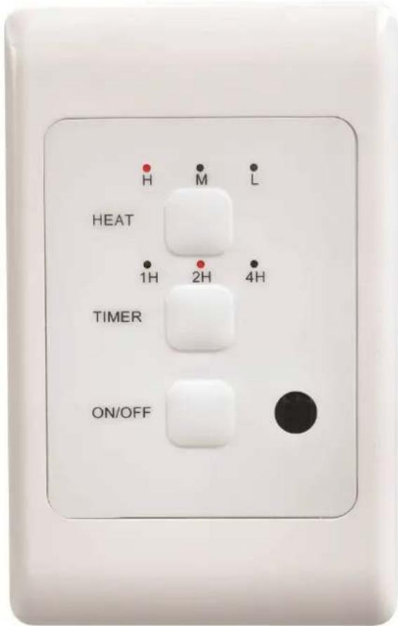
| MODEL MAXIMUM VOLTAGE (Volts) | MAXIMUM CURRENT (Amps) | PACKAGED DIMENSIONS (mm) | UNIT WEIGHT (kg) | |
| TT-MTM | 240 | 16 | 150 x 95 x 55 | 0.3 |
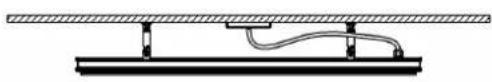
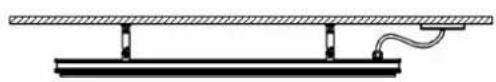
TT-MTM CONTROLLER INSTALLATION GUIDE
Controller Wiring Example
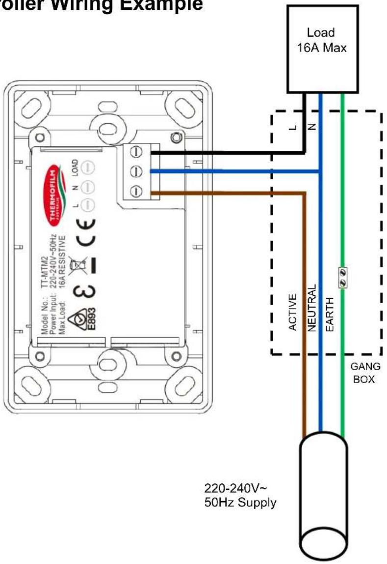
The TT-MTM controller requires sufficient air circulation in order to provide continuous operation on the high power load setting. The vents must remain clear at all times; never block or cover the vents.
An ideal controller installation will provide significant space around the back of the controller. Installing into restricted spaces, such as brick walls, may result in overheating if adequate ventilation is not provided.
Heater wiring schematic diagrams
It is recommended to install an ON/OFF isolation switch before the controller and ensure the unit is turned OFF after use.
Multiple heaters can be operated using a single controller, however the maximum current rating of 16A must not be exceeded. For direct wiring to the controller, the maximum is generally one heater unit unless the combined maximum current is less than 16A. For example, 2x THH1800A can be connected directly to the controller.
Below are example circuits indicating potential installation configurations.
Always check with your electrician and ensure all wiring is in accordance with local regulations.
For multiple units from one wall controller it is recommended to talk your electrician who will use a relay or contactor.
![graph LR subgraph_IN_SWITCHBOARD["IN SWITCHBOARD"] A1["ACTIVE"] --> B1["CIRCUIT BREAKER"] --> C1["RCD"] --> D1["ISOLATOR"] --> E1["TT-MTM2 WALL CONTROLLER MAXIMUM 16A"] --> F1["THH3200 HEATER"] --> G1["13.3A"] end subgraph_FIELD_WIRING["FIELD WIRING"] H1["ACTIVE"] --> I1["CIRCUIT BREAKER"] --> J1["R…](/content/2026/06/1211775/images/d05763537a41ff8422b77a3a07f7d6d7d5b1e6cc546c8e483d1f379e9d1ef543.jpg)
Heater wiring schematic diagram with relays
When more heating units need to be connected from the same controller a relay or contactor will be required. Below is an example circuit indicating one potential installation configuration. Always check with your electrician and ensure all wiring is in accordance with local regulations.
Note to electrician: The controller modulates the heat output using a "timed on / timed off" function. The controller does not modulate the voltage output. A relay is therefore suitable for this application.
CAUTION: A MINIMUM 250W LOAD MUST BE PLACED ACROSS THE CONTROLLER Failure to provide this minimum load will potentially damage both the relay/contactor AND
INCORRECT WIRING

CORRECT WIRING
![graph TD subgraph_IN_SWITCHBOARD["IN SWITCHBOARD"] A1["CIRCUIT BREAKER"] --> B1["RCD"] B1 --> C1["ISOLATOR"] C1 --> D1["TT-MTM2 WALL CONTROLLER MAXIMUM 16A"] D1 --> E1["THH3200A HEATER"] end subgraph_FIELD_WIRING["FIELD WIRING"] F1["CIRCUIT BREAKER"] --> G1["RCD"] G1 --> H1["ISOLATOR"] H1 --> I1["RE…](/content/2026/06/1211775/images/4a738a48a3375679865c24b72c1cf94ce9d3bcd5a3b0448a2329e284e95939a3.jpg)
Warranty Terms & Conditions
The below Warranty Terms and Conditions apply for New Zealand and Australia only. For international warranty please refer to international warranty terms and conditions.
Thermofilm warrants to the original owner that HEATSTRIP ® products will be free from defects in materials and workmanship for a period of 12 months from the date of purchase in accordance with the following warranty terms and conditions.
Provision of this warranty is subject to:
- The HEATSTRIP ® products must be installed in accordance with the Installation Instructions and relevant electrical standards and codes.
- The HEATSTRIP® products must be maintained and cleaned according to instructions detailed in the Installation Manual.
- There is no warranty expressed or implied with regard to capacity requirements. The selection of the unit or units depends entirely upon the system design and capacities as determined by the purchaser.
- The customer has not repaired, opened or altered the product in any unauthorised manner.
- This warranty excludes damage to the product or components arising from circumstances outside the control of Thermofilm, including, but not limited to, where the product is not used for intended purpose; where the product has been rectified in any way; incorrect installation; incorrect power supply; damaged caused during delivery; misapplication, misuse, abuse, vandalism, lack of maintenance or accident.
- Thermofilm's obligations under this warranty are limited to repair or replacement at Thermofilm's factory of any components of the product which Thermofilm identifies to its satisfaction to be defective.
- Transportation charges involved in return of the product to the Thermofilm factory (or any other location authorised in writing by Thermofilm) is the sole responsibility of the customer.
- All products are inspected and tested before despatch and are at the risk of the purchaser after the shipment from the Thermofilm factory, if not delivered by Thermofilm to destination.
- No products or components will be supplied in advance of an examination of the faulty product or components by Thermofilm or an authorized representative of Thermofilm.
- Thermofilm does not participate in any site related costs or labour expenses incidental to replacement of parts, repairing, removing, installing, servicing, transportation or handling of parts to complete products, and assumes no liability on parts repaired or replaced without written authorisation. Thermofilm shall not be liable for any default or delay in performance of its warranty obligations caused by any circumstances beyond its control, including, but not limited to, judicial or government restrictions, strikes, fires, floods, abnormal weather conditions, delayed supply of components.
Should products be determined as damaged on arrival, immediately notify the transport company of the condition and have them noted on the freight documents. If damage is discovered after unpacking, demand immediate inspection by the transportation company and insist that a record of the damage is made on the freight documentation.
The customer warrants using the product in accordance with:
- Any instructions provided to it by Thermofilm from time to time.
- All government and local regulations, including but not limited to all relevant electrical, environmental laws and regulations governing the installation, storage, use, handling and maintenance of the goods.
- All necessary and appropriate precautions and safety measures relating to the installation, storage, use, handling and maintenance of goods.
Our goods come with guarantees that cannot be excluded under the Australian Consumer Law. You are entitled to a replacement or refund for a major failure and for compensation for any other reasonably foreseeable loss or damage. You are also entitled to have the goods repaired or replaced if the goods fail to be of acceptable quality and the failure does not amount to a major failure.
All warranty requests for repairs or replacements must be accompanied by a complete "Warranty Claim Form" available from Thermofilm, together with proof of purchase (and where possible, photos of the installation) and the heater returned to the place of purchase.
In the event of a warranty claim, the goods need to be returned to the distributor/retailer for repair/replacement. Contact
Thermofilm Australia Pty Ltd
17 Johnston Court, Dandenong South, Victoria 3175, Australia
Telephone: (03) 9562 3455,
Email: info@thermofilm.com.au

- HEATSTRIP ® CLASSIC (THH-A)
- PRODUCT OVERVIEW
- EFFICIENT, COST EFFECTIVE ELECTRIC HEATING
- DESIGN FLEXIBILITY
- MINIMAL MAINTENANCE
- AUSTRALIAN MADE
- STYLISH DESIGN— THE HEATER THAT IS A DESIGN FEATURE
- EASY TO USE
- WHY CHOOSE HEATSTRIP® ELECTRIC RADIANT HEATERS FOR YOUR OUTDOOR OR HARD-TO-HEAT INDOOR AREA
- DISCRETE, STYLISH HEATING FOR UNDERCOVER OUTDOOR AND INDOOR OPEN AREAS
- SUBTLE, MINIMALIST DESIGN
- AUSTRALIAN PRODUCT
- SPECIFICATIONS - INTERNATIONAL
- OPERATING COST COMPARISON
- NOTES
- SPOT HEATING PRINCIPLE
- RADIANT FOOTPRINT
- SELECTION GUIDE
- TABLE LAYOUT
- INSTALLATION REQUIREMENTS
- INSTALLATION LOCATION — THE DIAGRAMS BELOW PROVIDE THE MINIMUM RECOMMENDED CLEARANCES IN MM
- MOUNTING OPTIONS
- STANDARD MOUNTING BRACKETS
- FLUSH MOUNT ENCLOSURE
- HEATSTRIP WALL MOUNTING KIT - (THHAC-028)
- INSTRUCTIONS
- SUSPENSION MOUNT BRACKET
- EXTENSION MOUNT BRACKET
- PERMANENT UMBRELLA MOUNTING GUIDE
- QUICK REFERENCE GUIDE FOR SPOT HEATING COMMON PERMANENT UMBRELLA STRUCTURE
- SAFETY
- MAINTENANCE
- HEATSTRIP PLUG IN REMOTE CONTROLLER
- DESIGN FEATURES
- HEATSTRIP® WALL CONTROLLER WITH REMOTE
- TT-MTM WALL CONTROLLER
- CONTROLLING MULTIPLE HEATERS
- REMOTE PAIRING
- TT-MTM CONTROLLER INSTALLATION GUIDE
- HEATER WIRING SCHEMATIC DIAGRAMS
- HEATER WIRING SCHEMATIC DIAGRAM WITH RELAYS
- INCORRECT WIRING
- WARRANTY TERMS & CONDITIONS
Brand : Heatstrip
Model : THH 1800A
Category : Heating