
VTC703AHD-Q2 - Security Camera Boyo - Free user manual and instructions
Find the device manual for free VTC703AHD-Q2 Boyo in PDF.

| Product Type | 7" 1080P Full HD Digital Wireless 2/4 Channel Monitor and Camera System with DVR |
| Monitor Display | 7" TFT IPS LCD, 1024x600 resolution, 16:9 aspect ratio |
| Camera Image Sensor | 1/3" CMOS, 1920x1080 effective pixels |
| Camera Video Transmission | 1080P AHD |
| Camera View Angle | 170° diagonal |
| Camera Night Vision | IR, up to 12 ft |
| Camera Audio | Built-in microphone |
| Camera Weatherproof Rating | IP68 |
| Wireless Frequency | 2.4 - 2.4835 GHz |
| Wireless Range | >300 ft (open line of sight) |
| DVR Recording | Per channel, up to 4 channels, 30 fps |
| DVR Recording Resolution | 640x480 or 1024x608 |
| DVR Storage | SD card (Class 10 or above), up to 128GB |
| Multiple View Modes | Single, dual, or quad split screen |
| Image Orientation | Flip horizontal/vertical, rotate 180° |
| Parking Guidelines | Selectable on/off |
| Operating Voltage | DC 12V & 24V (max 36V) |
| Power Consumption | <5W (monitor and camera each) |
| Working Temperature | -20°C to 70°C |
| Storage Temperature | -30°C to 80°C |
| Warranty | 1 year limited (excluding accessories) |
| Included Accessories | Monitor, cameras (2 for Q2), adapters, power cords, mounting hardware |
Frequently Asked Questions - VTC703AHD-Q2 Boyo
User questions about VTC703AHD-Q2 Boyo
0 question about this device. Answer the ones you know or ask your own.
Ask a new question about this device
Download the instructions for your Security Camera in PDF format for free! Find your manual VTC703AHD-Q2 - Boyo and take your electronic device back in hand. On this page are published all the documents necessary for the use of your device. VTC703AHD-Q2 by Boyo.
USER MANUAL VTC703AHD-Q2 Boyo
7" 1080P Full HD Digital
Wireless 2/4 Channel Monitor and Camera System
with Digital Video Recorder
USER MANUAL


natural_image
Four black-and-white surveillance cameras with visible antennas and signal waves, labeled 'Digital' in top-left corner (no other text or symbols)Please read the instructional complete before use and keep it for future reference.
Product Features
• 1080P Full HD Image Quality System
- 7" All View Angle IPS TFT LCD Panel
• 4 Channel Wireless Monitor with Single, Dual, or Quad View
• Waterproofed, Heavy Duty Wireless Camera
- Reliable Wireless Operational Range up to 300 ft
• Built-in Camera Microphone for Audio Monitoring
• Built-in DVR for Audio/Video Recording up to 4 Channels
- Easy Installation and Operation
Contents

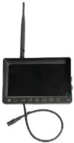
natural_image
Front view of a black electronic device with a wireless antenna and control buttons (no visible text or symbols)Monitor Set (1x)

Camera Set
(1x for 1Ch)
(2x for Q2)
(4x for Q4)

natural_image
Two types of cables: black USB connectors and red wire coils (no text or symbols visible)12V Adapter Power Chords
(2x for Ch)
(3x for Q2)
(5x for Q4)

Mounting HW
Before Installation
- Please check contents.
- Perform bench test. Ensure the product is working before installation by connecting the monitor and the camera to 12VDC.
- Perform pre-install test, before mounting the monitor and the camera. In very rare instances, a running engine causes interference, resulting in image freezing and jerky object movements. In such situation, the monitor and the camera need to be moved and positioned at various places to determine the best performance position.
- For recording, please use the high speed C10 SD memory card.
Wiring
| a. Monitor wiring: | |
 | Use 12V Adapter.OrUse a power chord.Power cordRED: to ACC+BLACK: to ground / chassis |
| b. Camera wiring: | |
 | Use a power chord.Power cordRED: to ACC+BLACK: to ground / chassis |
Monitor Installation
a. Install the monitor bracket using the 3 self-tapping screws.
- Screw in the center.
- Adjust the angle.
- Tighten all screws.
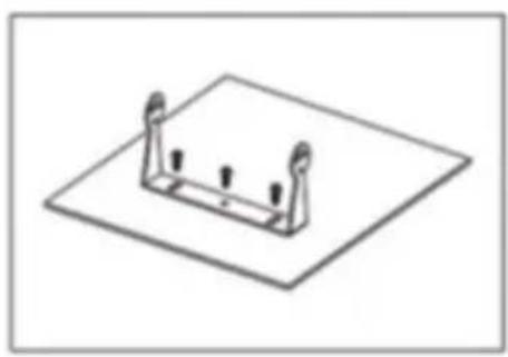
natural_image
Isometric line drawing of a mechanical bracket mounted on a flat base (no text or symbols)b. Install the monitor using 2 bolts on each sided.
* Do not tighten bolts.
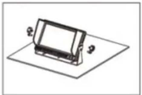
natural_image
Isometric line drawing of a rectangular electronic device mounted on a flat base (no text or symbols)c. Adjust the monitor angle.
* Tighten all bolts.

Operation
The wireless camera system is operated using the buttons on the front face of the monitor. These are 7 buttons.
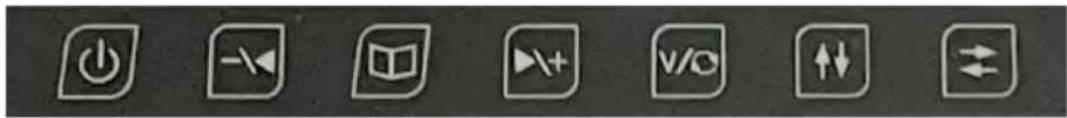
natural_image
Row of seven white square icons on dark background, including power button, navigation arrow, book, play button, video, upload/down, and double-headed arrow (no text or symbols)Each button has different function in three different modes. Three different modes are Split Screen Multi- Channel Display Mode, Single Channel Screen Display and Menu Display Mode.
1. Monitor Button Functions
Split Screen Multi-Channel Display Mode
| Button | Function | |
 | Screen Display On / Off | |
 | Audio Channel - | |
 | - | |
 | Audio Channel + | |
 | Display Mode: Display Channel 1 | |
 | Flip Screen Display Vertically | |
 | Flip Screen Display Horizontally | |
Single Channel Screen Display Mode
| Button | Function | |
 | Screen Display On / Off | |
 | Brightness - | |
 | Enter Menu Button | |
 | Brightness + | |
 | Display Mode: Next Channel | |
 | Flip Screen Display Vertically | |
 | Flip Screen Display Horizontally | |
Menu Mode
| Button | Function | |
 | Screen Display On / Off | |
 | Previous Menu Item | - Decrease |
 | Exit Menu | |
 | Next Menu Item | + Increase |
 | - | |
 | - | |
 | Select Submenu | Confirm |
2. Menu Button – Single Channel Screen Display Mode
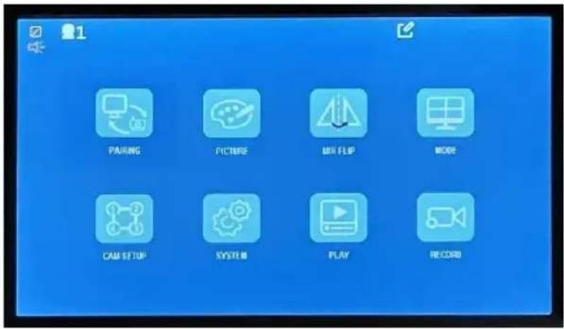

Pairing: By pairing assign a camera to each channel
Picture Setting: Brightness, Contrast, Saturation, Audio Volume
Picture Orientation: Flip L/R, Flip U/D
Screen Display Settings: Dual, or Quad split screen on/off
Camera Settings: Camera on/off, Display Scan time
System Settings: Set date/time, Set parking guidelines
Playback: Play back recorded video
Record Settings: Format SD, Rewrite on/off
3. Pairing:
For a wireless camera to transmit video to a monitor, each camera must be paired with specific monitor channel (or screen division).
In the following example, Ch 1 has been selected (Ch 1 single screen display mode).
Menu button is pressed.
'Pairing' is selected and the monitor starts count-down immediately.
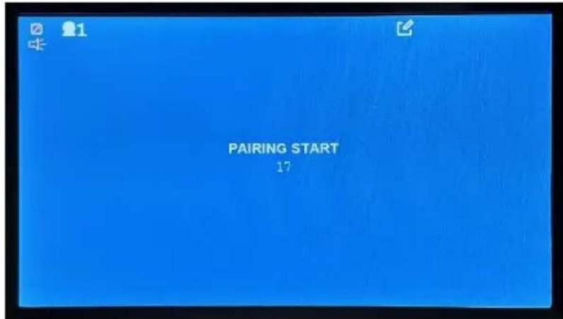
During the count-down, unplug and plug the camera power, couple of times.
When pairing is successful, the camera video will be displayed.
To stop pairing, press the menu button ( )
4. Picture Settings:

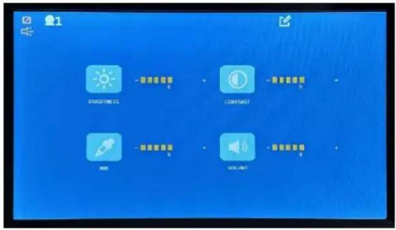
| Decrease | Increase | |||
 | Brightness | |||
 | Contrast | |||
 | Hue | |||
 | Volume | |||
5. Picture Orientation:


Normal Camera pointing forward:
An object at the front-right side of the vehicle is displayed on the right side of the screen.
Normal Camera pointing backward - installed as a rearview camera: Flip image horizontally.
An object at the rear-right side of the vehicle is displayed on the right side of the screen.
Normal Camera installed upside down:
Rotate the image (180 degrees) to get the normal view.
Rear view camera installed upside down:
Flip horizontally and rotate the image (180 degrees) to get the normal view.
6. Screen Display Setting:

The screen divisions, applicable to enabled cameras in “Camera Settings” are enabled (white colored) and non-applicable screen divisions are disabled (grayed out).
Use or button to the enabled screen division, and then use the OK button to select. Selected screen divisions will pink background 13
VTC703AHD-Q2: There are only two cameras and if they are paired with Ch 1 and Ch 2, then only will be enabled for selection. Other 2-screen divisions ( , and ) will be disabled (greyed-out).
VTC703AHD-Q4: If Camera 2 is turned off in the camera setting menu ( ), the screen divisions, ( , ) will be disabled from selection and grayed out.
When 'Split Off' () is selected, the split screen display will not be displayed.
7. Camera Settings:


ON: Selected camera is monitored and recorded.
OFF: Not monitored. Not recorded.

Auto Scan Time. Set the duration time for each channel to be displayed during auto scanning for monitoring purposes.

Auto Scan ON or OFF. Display a camera for the specified auto scan time and display next camera for the specified auto scan time. And so on.
Defaults:
VTC703AHD-Q2: Camera 1 and Camera 2 are turned on from the factory.
VTC703AHD-Q4: All cameras are turned on from the factory.
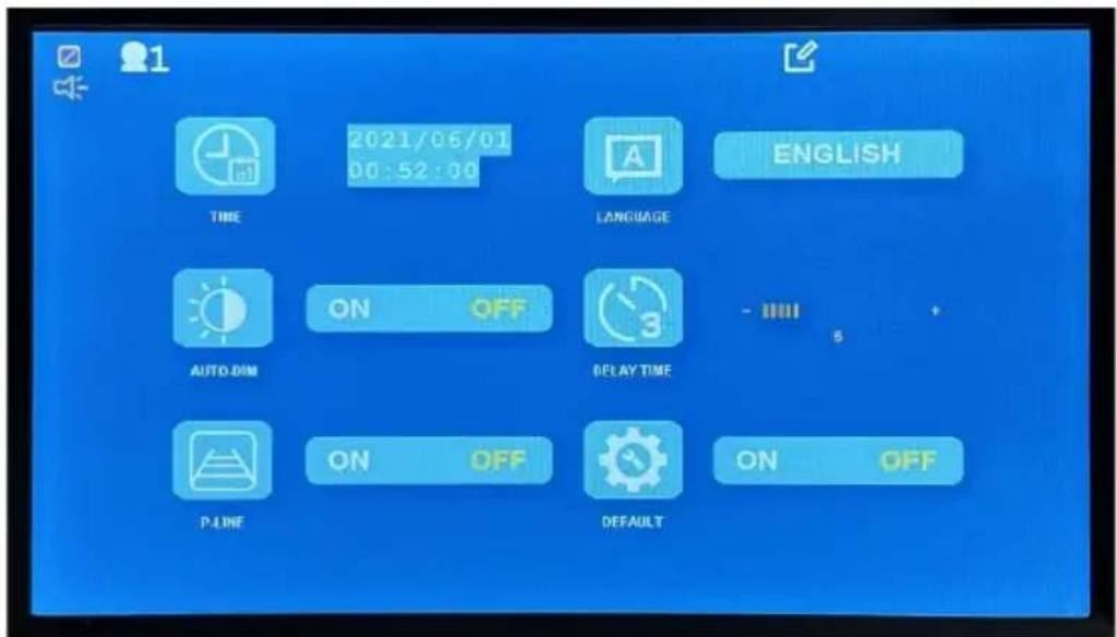
8. System Settings:


natural_image
Vertical blue icon set with white symbols including clock, speech bubble, sun, timer, gear, and wrench (no text or numbers)Set System Time
Select UI Language
Auto Dim On or Off. The setting dims the display when it becomes dark
Trigger off display – Not available in this version
Parking guidelines on/Off
Reset system to the factory defaults
9. Playback Recording:
The recorded video can be played on the monitor.
Here are steps:
a. From the main menu, select 'Play' and the available storage media will be displayed.

b. Select a storage media (by clicking the button) and the recording list will be displayed.

c. Use 'Up' or 'Down' button to a video file (.MP4) and press the 'select' button and the selected video will be played. d. The recorded video can be played by a PC media player. Remove SD card and place it in a PC.
10. Record Settings:


ON: Overwrite the oldest recording when storage is full.
OFF: Stop recording when storage is full.
ON: Format SD card. Support up to 128GB Class 10
1. Monitor Specification
Panel: 7" Digital Panel TFT IPS panel
View Angle: Full Angle of View
Resolution: 1024*600
Display Ratio: 16:9
Audio: Built-in Speaker with Volume Control Buttons
Image Control: Reverse / Non-Reverse (Horizontal Flip)
Parking Guidelines: Display / No-Display (Selectable)
Operating Voltage : DC12V & DC24V (MAX. to 36V)
Power Consumption: Less than 5W
Max. Current: Less 450mA
Storage temperature: -30^ 80^
Working temperature: -20^ to 70^
2. Camera Specification
Image Sensor: 1/3 CMOS sensor
Effective Pixels: 1920 x 1080
Video Transmission: 1080P AHD
View Angle: 170^ (Diagonal)
IR Night Vision: IR
Night Vision IR distance: up to 12ft
Audio: Microphone Built-in
Environment: IP68
Operating Voltage: DC 12V & 24V
Power Consumption: < 5W
Max. Current: < 450mA
Storage temperature: -30^ 80^
Working temperature: -20^ to 70^
3. Wireless Specification
Operating frequency: 2.4GHz\~2.4835GHz
Output Power: 17±1dBm @TYp 20dBm@max (if necessary)
Modulation Type: FSK/GFSK
RX Sensitivity: -89dBm(Typical)@4MHz BER:<1E-3
RF Bit Rate: 4MHz BER<1E-3
Spread Spectrum: FHSS
Distance: >300 ft Open Line of Sight
4. DVR Specification
Recording: Per channel
Resolution: 640x480 or 1024x608
Frame per Second 30fps
Memory Card SD Class 10 or above
Storage Size Max. 128GB
WARRANTY INFORMATION
This one-year limited warranty is given to the end-user or the retail purchaser (referred to this warranty as “Original Purchaser”) that it will be free from defects in material and workmanship for a period of one year from the date of the purchase of the new product (excluding accessory items such as power cords, cradle, memory card, adaptor, and cables).
This limited warranty does not cover any physical damage to, or misuse of, this product, damage caused by improper installation; improper use; misuse; neglect; repair of cracked, scratched, broken or modified cosmetics; or parts that have been altered or removed; damages done by another device used with this product resulting from use of non BOYO®-brand parts. This warranty is VOID if you purchased this product as used, floor model sample, or refurbished; if the product has been altered or modified in any way (including but not limited to attempted repair without authorization from BOYO®- Vision Tech America, Inc. and/or alteration/removal of the serial number).
For warranty information, visit: https://www.visiontechamerica.com/get-warranty
1 YEAR LIMITED WARRANTY
This limited warranty is given to the end-user or the retail purchaser (referred to this warranty as "Original Purchaser") that it will be free from defects in material and workmanship for a period of one year from the date of the purchase of the new product (excluding accessory items such as power cords, cradle, memory card, adaptor and cables). A copy of the original proof of purchase and this warranty card with RMA number given by Vision Tech America, Inc. is required to receive warranty service. In the unlikely event that the new product should fail due to defect in material or workmanship, Vision Tech America, Inc. will repair or replace with new or refurbished product, where each party will be responsible for one-way shipping for the lower 48 states customers only. For International and U.S customers residing in Hawaii, Alaska and Puerto Rico, customer is responsible for freight charges incurred both ways.
This limited warranty does not cover any physical damage to this product, damage caused by improper installation; improper use; misuse; neglect; repair of cracked, scratched, broken or modified cosmetics; or parts that have been altered or removed; damages done by another device used with this product resulting from use of non BOYO®- brand parts. This warranty is VOID if you purchased this product as used, floor model sample, or refurbished; if the product has been altered or modified in any way (including but not limited to attempted repair without authorization from BOYO®- Vision Tech America, Inc. and/or alteration/removal of the serial number). This limited warranty does not cover the vehicle of any damages or liabilities in which this product is installed or being installed. This product does not guarantee avoidance of vehicle collision or accident.
If you are having trouble with the product, please contact our technical support at 888-941-3060 or email: info@visiontechamerica.com with your questions or comments. If your product is eligible to receive warranty, request for warranty service online by visiting http://visiontechamerica.com/site/get-warranty/
This warranty is invalid if the factory applied serial number has been altered or removed from the Product.
IMPORTANT: TO SEND DEFECTIVE PRODUCT FOR WARRANTY SERVICE, YOU MUST RECEIVE RMA (RETURN MATERIAL AUTHORIZATION) AND INCLUDE ORIGINAL PROOF OF PURCHASE AND THIS WARRANTY CARD WITH THE SHIPMENT.
VISION TECH AMERICA CUSTOMER SERVICE CENTER 888-941-3060 or visit www.visiontechamerica.com
For an accessory or part not available from your authorized dealer, call For U.S. 888-941-3060 | International 714-446-0543
BOYO®
Product Registration
Vision Tech America, Inc.
Name
Address
City
Phone
Model No.
Purchased Date
City/State of Store
Company
State____ Zip____
Email:
Serial No.
Store Name

BOYO®
Vision Tech America, Inc.
1452 E. Valencia Drive
Fullerton, CA 92831
BOYO®
Vision Tech America, Inc.
Product Registration
Name
Address
City ____ ____
Phone
Model No.
Purchased Date
City/State of Store
Company
State____ Zip____
Email:
Serial No.
Store Name
Place Postage Stamp
Here
BOYO®
Vision Tech America, Inc. 1452 E. Valencia Drive Fullerton, CA 92831

- USER MANUAL
- Product Features
- Contents
- Before Installation
- Wiring
- Monitor Installation
- Operation
- Monitor Button Functions
- Menu Button – Single Channel Screen Display Mode
- Pairing:
- Picture Settings:
- Picture Orientation:
- Normal Camera pointing forward:
- Normal Camera pointing backward - installed as a rearview camera: Flip image horizontally.
- Normal Camera installed upside down:
- Rear view camera installed upside down:
- Screen Display Setting:
- Camera Settings:
- Defaults:
- System Settings:
- Playback Recording:
- Record Settings:
- Monitor Specification
- Camera Specification
- Wireless Specification
- DVR Specification
- WARRANTY INFORMATION
- YEAR LIMITED WARRANTY
- BOYO®
- Product Registration
Brand : Boyo
Model : VTC703AHD-Q2
Category : Security Camera