
15800B - Industrial sewing machine Union Special - Free user manual and instructions
Find the device manual for free 15800B Union Special in PDF.

| Product Type | Industrial Sewing Machine |
| Brand | Union Special |
| Model | 15800B |
| Category | Flat Bed, One Needle, With Trimmer |
| Bed Length | 10 inches (low bed) |
| Stitch Type | Double Locked Stitch |
| Needle Type | Type 106 (round shank, round point, extra short, double groove, ball eye, nickel plated) |
| Number of Needles | 1 |
| Feeding Mechanism | Tandem differential feed (main and differential feed dogs) |
| Trimming Mechanism | Spring-pressed knife engagement |
| Lifter | Floor treadle lifter |
| Stitch Length Adjustment | By stitch regulating screw at left end of main shaft |
| Needle Thread Controller | Non-automatic (manual adjustment) |
| Binding Attachment | Adjustable for width of binding (3/4, 7/8, 1 inch) |
| Width of Seam | Adjustable by moving lower knife support; up to 1 inch |
| Knife Sharpening | Knife grinder available (optional, model 15898B or 15898D) |
| Lubrication | Oil; felt lubricating sections for main shaft |
| Repair Parts | List of parts with symbols, including plus sizes for worn bearings |
| Manual Included | Yes, 82 pages (PDF) |
| Primary Applications | Seaming and binding coats, bathrobes, mackinaws, and similar heavy garments |
Frequently Asked Questions - 15800B Union Special
User questions about 15800B Union Special
0 question about this device. Answer the ones you know or ask your own.
Ask a new question about this device
Download the instructions for your Industrial sewing machine in PDF format for free! Find your manual 15800B - Union Special and take your electronic device back in hand. On this page are published all the documents necessary for the use of your device. 15800B by Union Special.
USER MANUAL 15800B Union Special
Industrial Sewing Machines
Instructions
for
Adjusting and Repairing with
List of Parts
Styles
13200A
15800A
15800B
15800D
15800E
15800G
15900 A
15900D
15900E
CATALOG
No.51B
Second Edition
ADJUSTING AND REPAIRING
Styles
13200 A
15800 A
15800 B
15800 D
15800 E
15800 G
15900 A
15900 D
15900 E
With List of Parts
Main Office and Factory: 400 North Franklin Street
CHICAGO, U. S. A.
BRANCHES AND SERVICE STATIONS, UNITED STATES
Boston, Mass.
210 Lincoln St.
Tel. Liberty 0148
New York, N. Y.
65-69 Bleecker St.
Tel. Spring 7-8888
Johnson City, N. Y.
49 Cherry St.
Tel. 7-3179 and 7-5423
Waterford, N. Y.
22 4th St.
Tel. 467
Philadelphia, Pa.
401 N. Broad St
Tel. Bell-Walnut 3131
Key.-Race 1078
Cincinnati, Ohio
422-425 Temple Bar Bldg.
Tel. Parkway 2521
Cleveland, Ohio
1276 W. 3rd St.
Tel. Main 9657
Atlanta, Ga.
153 Spring St.
Tel. Main 3377
St. Louis, Mo.
1127 Pine St
Tel. Main 1776
Kansas City, Mo.
5014 College Ave.
Tel. Wabash 6966
Los Angeles, Calif.
307 F. W. Braun Building
1240 So. Main St.
Prospect 5636
San Francisco, Calif.
682 Mission St
Tel. Garheld 7999
SERVICE REPRESENTATIVES, UNITED STATES
Baltimore, Md.
17 Guilford Ave.
Tel. Plaza 4262
Newark, N. J.
60 Park Place
Tel. Mulberry 4-3123
Greensboro, N. C.
108 So. Aycock St.
Tel. 6301
Detroit, Mich.
2725 Boston Blvd., W.
Tel. Euclid 4118
Nashville, Tenn.
203 Golf Club Lane
Tel. 7-7937-J
Minneapolis, Minn.
3608 27th Ave., South
Tel. Drexel 3331
Ft. Worth, Texas
912 Morningside Drive
Tel. 4-7776
Seattle, Washington
2128 Westlake Ave.
Tel. Eliot 0144
York, Pa.
49 N. George St.
Tel. 2886
BRANCHES—FOREIGN
Union Special
Union Special
Union Special
Union Special
Union Special
Union Special
Onion Special
Compagnie de
Compagnie de
Machine Corporation of America.
Machine Company of Canada, Ltd.
Machine Company of Canada, Ltd.
Machine Corporation of America.
Machine Company, Ltd.
Machine Company, Ltd.
Machine Company, Ltd
Machines Union Special de France.
Machines Union Special de France.
Belgium, Brussels
Canada, Toronto
Canada, Montreal
Denmark, Copenhagen
England, Leicester
England, London
England, Manchester
France, Paris
France, Lyons
UNION SPECIAL MASCHINENFABRIK, G. m. b. H.
General Office and Factory: STUTTGART, GERMANY
BRANCHES AND SERVICE STATIONS, GERMANY
Berlin
Chemnitz
Köln
Ebingen
Frankfurt am Main
Foreign Distributors and Service Stations Are Found in:
Argentine Republic
Buenos Aires
Austria
Vienna
Australia
Brisbane
Melbourne
Perth
Sydney
Brazil
San Paulo
Pernambuco
British West Indies
Kingston
Chile
Santiago
China
Hong Kong
Shanghai
Tientsin
Cuba
Havana
Finland
Tammerfors
Hawaiian Is
Honolulu
India
Bombay
Calcutta
Italy
Italy
Mian
Japan
Osaka
Tokyo.
Mauritius
Port Louis
Mexico
Mexico City
Monterrey
Netherlands
therlands
Amsterdam
New Zealand
Auckland
Christchurch
Wellington
Dunedin
Norway
Oslo
1
Philippine Islands
Manila
Peru
Lima
Portugal
Oporto
Puerto Rico
San Juan
Scotland
Glasgow
Dundee
South Africa
Johannesburg
Durban
Capetown
Port Elizabeth
Spazin
Barcelona
Sweden
each Bears
Borås Stockholm
Switzerland
Zurich
Uruguay
Montevideo
Copyright, 1925, by Union Special Machine Co.
CONTENTS
Page
Application of Catalog.... 3
Identification of Machines.... 4
Adjusting 6
Formation of the Double Locked Stitch....6
Tensions 12
Regulating Length of Stitch....14
Setting Binding Attachment....14
Trimming Mechanism....15
Setting the Knives....16
Changing Width of Seam....16
Knife Grinder....18
Grinding the Knives....18
Repairing 21
Assembling 22
Needles 24
Ordering Repair Parts....25
Plates 26
List of Parts....56
PROPERTY OF DEVELOPMENT/CATALOG DEPT.
Please return to the Catalog Dept.
Date received to file: DEC 08 1992
APPLICATION OF CATALOG
This catalog applies only to the styles of machines with gauges and widths of binding as specified below.
| Styles | Gauges | Widths of Binding |
| 13200 A | 2 | 34 , 78 , 1, 118 |
| 13200 A | 4 | 34 , 78 , 1, 118 |
| 15800 A | 34 , 78 , 1, 118 | |
| 15800 B | 34 , 78 , 1 | |
| 15800 D | ||
| 15800 E | ||
| 15800 G | ||
| 15900 A | ||
| 15900 D | 34 , 78 , 1, 114 | |
| 15900 E |
It can be applied with discretion to other styles.
Instructions for installing and operating these machines, together with illustrations of oiling and threading diagrams, are found in Catalog No. 51 A. Information relative to the transmitter is contained in Catalog No. 29. Needles are listed and fully described in Catalog No. 45. These catalogs will be furnished gratis on request.
IDENTIFICATION OF MACHINES
A machine equipped with specified parts and fitted for a specific operation is given a STYLE NUMBER, the symbol for which is a number evenly divisible by 100, with a letter affixed. Example: 13200 A, 15800 D, 15900 D.
Styles of machines, similar in construction, are grouped and given a CLASS NUMBER, the symbol for which is a number evenly divisible by 100, without a letter affixed. Example: 13200, 15800, 15900.
Attached to each machine will be found a name plate, stamped with either the style number or the class number.
The measurement of the space between the rows of stitching made by styles in Class 13200 is represented by a gauge number. The spacing of the gauges is as follows: 2 gauge, 18 inch; 4 gauge, 3/16 inch.
STYLES OF MACHINES IN CLASS 13200
Flat Bed, Two Needles, Two Loopers, Right Hand Needle In Front, With Trimmer, Low Bed, 10 Inches Long, Needle Lever Connection Under Arm.
13200 A For seaming and binding, in one operation, dresses, crash clothing, bathrobes, and similar garments made from fabrics which fray readily, spring-pressed knife engagement trimming mechanism, double locked stitch, floor treadle lifter, Type 106 needles.
13200 Z A special style similar to the standard styles in Class 13200, but not specifically defined. It is always fitted with one or more parts differing from the fitting of any of the standard styles in the class, and is often fitted for a different operation.
STYLES OF MACHINES IN CLASS 15800
Flat Bed, One Needle, With Trimmer, Low Bed, 10 Inches Long, Needle Lever Connection Under Arm.
15800 A For seaming and binding dresses, shirt waists, and similar garments, spring-pressed knife engagement trimming mechanism, double locked stitch, floor treadle lifter, Type 106 needles.
15800 B For binding coats, bathrobes, mackinaws, and similar garments, spring-pressed knife engagement trimming mechanism, double locked stitch, tandem differential feed, floor treadle lifter, Type 106 needles.
IDENTIFICATION OF MACHINES
15800 D For seaming sweaters and heavy-weight knitted materials, fixed knife engagement trimming mechanism, double locked stitch, tandem differential feed, minimum width of seam 18 inch, floor treadle lifter, Type 121 needles.
15800 E For closing toes of heavy-weight stockings, seaming light weight knit underwear and other light-weight material, fixed knife engagement trimming mechanism, double locked stitch, tandem differential feed, minimum width of seam 1/16 inch, floor treadle lifter, Type 121 needles.
15800 G For seaming fleece lined underwear and other medium-weight knitted garments, fixed knife engagement trimming mechanism, double locked stitch, minimum width of seam 18 inch, floor treadle lifter, Type 121 needles.
15800 Z A special style similar to the standard styles in Class 15800 but not specifically defined. It is always fitted with one or more parts differing from the fitting of any of the standard styles in the class, and is often fitted for a different operation.
STYLES OF MACHINES IN CLASS 15900
Flat Bed, One Needle, Low Bed, 10 Inches Long, Needle Lever Connection Under Arm.
15900 A For seaming seat and inseam of trousers, seaming coats and similar garments, double locked stitch, floor treadle lifter, Type 128 needle.
15900 D For binding aprons, dresses and similar garments, double locked stitch, floor treadle lifter, Type 106 needle.
15900 E For stitching rick-rack braid to dresses, aprons and similar garments, folder for edge of body fabric and adjustable guide for braid, double locked stitch, floor treadle lifter, Type 106 needle.
15900 Z A special style, similar to the standard styles in Class 15900, but not specifically defined. It is always fitted with one or more parts differing from the fitting of any of the standard styles in the class, and is often fitted for a different operation.
ADJUSTING
GENERAL PLAN The steps necessary to readjust the machine or check its adjustment are given in the order most convenient for the machine fixer to follow.
The styles in Class 13200 use two needles and two loopers which make them slightly different from styles in Classes 15800 and 15900, which use only one needle and one looper. The instructions given apply directly to styles in Classes 15800 and 15900. Their application to styles in Class 13200 is a simple matter as the mechanism is practically the same. Where it differs, specific adjusting information is furnished.
In describing the positions or movements of the parts, there is but one point of view used. It is that of the operator sitting in front of the machine.

FORMATION OF THE
The accompanying illustrations "DOUBLE LOCKED STITCH" show the three steps in the formation of the "double locked stitch." A careful study of them and the explanatory matter will be of considerable assistance in making an adjustment. Frequent references to these illustrations are made.
The needle carries its thread down through the fabric and, as it ascends, throws out a loop at the rear, which the looper enters as
ADJUSTING
shown in Fig. 1. While the needle is above the throat plate, the feed dog moves the fabric to the rear, the looper rocks to the front across the path of the needle and returns to the right, forming a triangular space—bounded by the back of the looper, the looper thread on the left and the needle thread on the right—into which the needle descends with its thread, as shown in Fig. 2. The looper, continuing to return to the right, leaves the stitch on the needle, as shown in Fig. 3. The needle, again ascending, recedes from the stitch, which is tightened in the fabric by the action of the looper as it forms the next stitch.
The tension applied to the needle thread controls the tightness of the stitches.
CAUTION When a machine fails to work satisfactorily, though apparently in good repair, it is possible that some minor trouble exists. For this reason, delay may be avoided by acting on the following suggestions:
(1) Check the machine according to operating instructions under the subject "Useful Hints" in Catalog No. 51 A.
(2) See that the needle thread tensions are as tight as is consistent with the strength of the thread. See that the looper thread tensions are quite loose. The looper threads require only a slight tension, barely enough to steady them in passing through the machine.
(3) The throat plate needle hole, thread eyelet, tension discs, and needle thread take-up may have become roughened or grooved, which will cause breaking of both the needle and looper threads. It can be remedied by smoothing the surfaces with emery cloth.
(4) Unravel the stitching and note if the threads are cut or injured. The teeth of the feed dog may be cutting the stitch on the under surface of the fabric.
(5) Before operating by power, after any change has been made in the working parts, always turn the machine by hand, to be sure that it runs freely and that the working parts do not interfere with the frame or with each other.
If the foregoing suggestions fail, the adjustment should be checked with the following instructions. While many variations can be made, the best results will be secured by following them.
ACCESSIBILITY To secure an unobstructed view of the looper, remove the cloth plate and looper needle guard.
Note: In adjusting machines, always use a new needle.
NEEDLE REAR GUARD This forces the needle into proper position, should it glance toward the rear of the machine in passing
ADJUSTING
through the fabric. Three types are used in the machines covered by this catalog.
Styles 15900 A, 15900 D, and 15900 E are equipped with a stationary type. It is fastened in a seat milled in the under side of the throat plate. A slight variation in its position can be secured by slightly loosening the screw and forcing the guard in the desired direction while the screw is retightened. It is set correctly when its vertical face barely touches the rear of the needle.
Styles 15800 D, 15800 E and 15800 G are also equipped with a stationary type, adjustably secured to the lower knife support. It is set correctly when its vertical face barely touches the rear of the needle.
Styles in Class 13200, Styles 15800 A and 15800 B are equipped with a moving type secured to the feed bar. It is set correctly when its vertical face or faces barely touch the rear of the needle when the guard is at its extreme forward position.
As it moves with the feed dog, the guard must be readjusted each time the length of the stitch is altered.
The needle bar in styles in Class 13200 should be turned in its bearings so that the oblique position of the needles corresponds with the oblique position of the two vertical faces of the needle rear guard.
LOOPER COLLARS These are placed over the shanks of loopers in Styles 13200 A, 15900 D, and 15900 E. They are furnished in three thicknesses. No. 21210 is .040 inch thick, No. 21210 A is .020 inch thick, and No. 21211 is .054 inch thick. Additional variations can be secured by driving the collar into the end of a wooden block and reducing its thickness with a file. The collars used should be of sufficient thickness so that when the loopers are seated in the looper rocker, the smallest space between the top of the loopers and underside of throat plate, when the loopers are in their highest position, is just enough to pass a double thickness of newspaper.
NEEDLE AND LOOPER Three adjustments are necessary to bring these in proper time.
FIRST The space between the center of the needle and ADJUSTMENT point of the looper, when the needle is at its lowest position, should be 7/32 inch. This space controls the size and form of needle loop. A very convenient manner of securing an accurate adjustment will be found by using a looper adjusting gauge No. 21225-7/32, having a "V" slot, the center of which is 7/32 inch from the edge of the wider side, as indicated by the dotted line in the cut. In using this gauge, hold it with the "V" slot enclosing
ADJUSTING
the front of the needle, with the wider side of the gauge to the right. Then, the needle being at its lowest position, the point of the looper should be made to come even with the right-hand edge of the gauge
by turning the looper connecting rod, which is provided with right and left threads. To loosen nuts, use wrench No. 21388 and turn them to the rear. In tightening the looper connecting rod nuts, care should be taken to see that

natural_image
Black-and-white illustration of a wooden plank with a hole and textured surface (no text or symbols)21225-7½
the left ball joint has side play in all positions. First tighten the left nut securely. Then, turn the pulley in the operative direction till the long straight edge of the looper thread take-up is in its front vertical position and tighten the right-hand nut securely. Again apply the gauge to make sure that the adjustment has not been altered.
The front looper of styles in Class 13200 should likewise be set to the 7/32 inch gauge. With this adjustment of the front looper, the distance from the point of the back looper to the center of the back needle should be approximately the same. If the distance is greater, set the back looper to the looper gauge by turning the looper connecting rod.
SECOND To set the needle at its proper height with respect to the looper, turn the machine pulley in its operative direction till the point of the looper, moving from right to left, is even with the left side of the needle. Then the measurement from the under side of the looper to the upper edge of the needle eye should be 1/64 inch for Styles 15800 A, 15900 D, and 15900 E; 1/32 inch for Style 15900 A; and 3/64 inch for Styles 13200 A, 15800 D, 15800 E and 15800 G. Enough variation is allowable to have the upper edge of the needle eye 1/64 inch lower than the foregoing measurements, without interfering with the functions of the loopers and needles, as shown in Figs. 1 and 2, respectively, of the stitch formation. The adjustment is made by moving the needle bar.
Care should be taken when adjusting styles in Class 13200 to avoid turning the needle bar in its bearings, as that will destroy the oblique adjustment of the needles. An excellent plan is as follows: Place the fingers of the left hand back of the presser guide bar bearings, and press the thumb firmly against the front of the needle bar. With the right hand, loosen the two needle bar set screws, and turn the pulley so that the needle bar connection will be moved upward if the needle bar is to be lowered; turn the pulley in the opposite direction if the needle bar is to be raised.
ADJUSTING
THIRD When the looper moves to the left to enter the ADJUSTMENT needle loop as shown in Fig. 1 of the stitch formation, there should be approximately .010 inch space between the looper point and the back of the needle. A space of .010 inch is easily visualized by cutting three plies of newspaper simultaneously with a pair of sharp scissors and bringing the cut edge into view by holding the paper together with both hands. A variation from .005 to .0156 (1/64 inch) is allowable. To adjust the position of the looper, turn the pulley till the looper point is directly behind the needle; loosen the two screws which hold the looper rock shaft frame to the bed; move the frame to the front till the looper point noticeably deflects the needle; tighten the screws slightly to force the frame into a level position; tap the frame backward to the desired position with the handle of a screw driver; retighten the frame screws securely.
A small piece of white paper placed to the left of the needle as a background will be found convenient in making this adjustment.
NEEDLE FRONT A guard is attached to the looper to force the GUARD needle into its proper position should it glance toward the front of the machine in passing through the fabric. The guard is set correctly when it barely passes the needle without striking it. The screw hole is elongated to permit this adjustment.
On styles in Class 13200, the foregoing applies only to the front looper.
LOOPER THREAD TAKE-UP Near the middle of the main shaft AND CAST-OFF WIRE is located a device for controlling the looper thread. It consists of a take-up, cast-off wire, and take-up thread eyelet. Their function is to hold the looper thread taut till the descending needle point has passed below the looper thread as shown in Fig. 2 of the stitch formation, and continue to hold the thread till the eye of the looper is to the left of the middle of the needle, then release it.
A simple test to determine whether they are in adjustment can be made as follows: Take hold of the looper thread on the left side of the thread eyelet, draw it slowly through the eyelet, and while so doing, turn the machine pulley in its operative direction, until the thread moves from the long straight edge of the take-up to the circular edge. Stop at this point. The needle point should be below the middle of the looper. Enough variation is allowable to have the point even with the lower edge of the looper.
The prongs of the take-up thread eyelet, which project over the main shaft, are set correctly when they just clear the main shaft
ADJUSTING
sleeves. To change the height of the prongs, loosen the lock nut on the stop screw and change the position of the stop screw in the take-up thread eyelet holder.
INTERMITTENT LOOPER THREAD NIPPER SPRINGS
Attached to the front side of the main shaft middle bearing is a pair of nipper springs, which clamp the looper thread when the looper is moving to the right. Their purpose is to prevent the take-up from drawing additional looper thread through the tension instead of holding taut the thread where it passes from the looper eye to the throat plate needle hole as shown in Fig. 2 of the stitch formation. They are set correctly when they begin to clamp the thread as soon as the looper has completed its movement to the left and returned about 1/64 inch. Their operation can readily be observed by threading the machine in the regular manner and drawing the thread, care being taken to leave some slack between the tension and the nipper springs. The adjustment is made by changing the position of the operating arm on the looper rock shaft.
NEEDLE BAR Fastened to the needle bar is a thread nipper. THREAD NIPPER Its purpose is to counteract the elasticity of the needle thread and enable the needle to throw out steady loops. The slightest appreciable tension is all that is required. The adjustment is made by lengthening or shortening the spring.
FEED DOGS It is important that the feed dog be set at just the proper height above the throat plate. If the tips of the teeth do not rise high enough, imperfect feeding of the work will result. If they rise too high, imperfect feeding of the work will likewise result, because the teeth will remain in contact with the fabric after the motion of the feed dog has reversed. The feed dogs should be set so that the tips of their teeth will rise approximately 3/64 inch above the throat plate. Variations to insure proper feeding and consistent with the fabric are allowable. There are two types of feeding mechanism used in machines covered by this catalog, non-differential and differential.
NON-DIFFERENTIAL FEEDING MECHANISM This consists of a single feed dog adjustably secured to the feed bar. Its height is maintained by a supporting screw under the feed dog.
DIFFERENTIAL This consists of two feed dogs, a main FEEDING MECHANISM feed dog and a differential feed dog. They are both adjustably secured to their respective feed bars. The differential feed bar is driven by a link, adjustably secured by a
ADJUSTING
stud to a slot in the feed rocker. When the stud is in its lowest position in the slot, the differential feed dog travels in unison with the main feed dog. The desired differential motion can be obtained by raising the stud. If the travel of the differential feed dog relative to the main feed dog is too long, it will gather or shorten the fabric at the seams. If its travel is too short, it will stretch or lengthen the fabric. Care should be taken to see that the feed dogs do not strike the ends of the throat plate slots.
PRESSURE On top of the machine near the middle will be found a thumb screw for regulating the pressure of the presser foot on the fabric. Only sufficient pressure is required to enable the machine to feed properly and to firmly hold the fabric while the needles are being withdrawn. Care should be taken to avoid tightening the screw to the extent that the spring rests on the machine bed because this condition will decrease the pressure.
TENSIONS The importance of properly adjusted tensions can scarcely be over-estimated. Not only the required tightness or looseness of the stitches, but their uniform appearance is dependent on this adjustment.
For stitching inelastic fabrics, the tension on the needle threads should be as tight as is consistent with their strength and avoid puckering the fabric. For stitching elastic fabric such as knitted goods, the tension on the needle threads should be considerably less to secure the desired elasticity in the stitches.
The tension on the looper threads should be very slight; only sufficient to steady them in passing through the machine.
THREAD For regular stitching, the needle thread should be two or three sizes larger than the looper thread. While a glaze or soft finish thread can be used in the needle, a soft finish is always preferable in the looper.
NEEDLE THREAD While only one type of needle thread controller is used on each machine, two types are used on the machines covered by this catalog. The automatic type is used on machines in Classes 13200 and 15900 and the non automatic type on machines in Class 15800.
AUTOMATIC NEEDLE On the upper part of the machine will THREAD CONTROLLER be found a lever, connected with the presser bar. It carries a guide for the needle thread at its right-hand end, which co-operates with two eyelets fastened to the needle lever, one to the right and the other to the left.
ADJUSTING
Its purpose is to take up the slack in the needle thread while the looper is returning to the right. As it is connected with the presser bar, it automatically adjusts itself for any thickness of fabric; that is, when the presser foot ascends or descends, as thicker or thinner fabric passes under it, the thread controller guide moves in the opposite direction, and takes up a decreased amount of slack on the thicker fabric, or an increased amount on the thinner fabric.
The adjustment can only be made by threading the machine and running it on the fabric.
Where a tight seam is required, which necessitates a tension on the needle thread as tight as consistent with its strength, the thread controller guide should be set so that, when the needle is at its lowest position, there will be the smallest noticeable slack in the thread. If there is no slack the thread controller guide may have to be lowered, as the needle, moving at full speed, descends a trifle farther and the strain at the eye will cause frequent breaking of the thread. If there is more than 1/16 inch of slack, the guide may have to be raised; otherwise, the stitch around the needle will remain below the throat plate and will interfere with the formation of the needle loop, as the looper moves to the left in the formation of the new stitch.
Where a comparatively loose tension is required to avoid puckering the fabric, or for operations where the machine has to continue to make stitches, after the fabric has passed beyond the needle, the thread controller guide should be set a trifle higher.
The position of the guide is altered by moving the rack on the presser bar.
If any needle thread is drawn through the tension as the needle descends, it may be accurately observed while turning the pulley by hand.
To ascertain the amount of slack in the needle thread, turn the pulley till the needle passes down through the fabric to its lowest position, place the fingers on the thread a short distance above the needle clamp nut, and draw upward.
The thread controller guide should never be set so that it will descend lower than 1/32 inch below a straight line connecting the two eyelets on the needle lever, when the needle is at its highest position and the presser foot is bearing on the thickest part of the work, as its action would be interfered with.
NON-AUTOMATIC NEEDLE THREAD CONTROLLER
Its purpose is the same as the automatic type except that it is non-automatic in operation. It is usually set as high as its slot will permit.
ADJUSTING
REGULATING
LENGTH OF STITCH
This is accomplished at the left end of the main shaft. There, three screws in a row will be found with a lock nut to the left of them. The length of stitch is altered by loosening the nut and turning the stitch regulating screw which is the largest of the three. Turning it to the right lengthens the stitch, and turning to the left shortens it. To loosen nut, use screw driver wrench No. 21206 and turn it in the direction the machine runs. Apply the wrench with the left hand and hold the machine pulley with the right hand.
Always tighten the lock nut after any change has been made. Note the effect of turning the stitch regulating screw. If it is turned too far to the right, the feed dogs will strike the ends of the slots in the throat plate. If it is turned too far to the left, the machine will feed the work towards the operator.
Each time the length of stitch is altered on machines having a needle rear guard attached to the feed bar, the guard must be readjusted to compensate for the change.
SETTING BINDING ATTACHMENT
It should be set as close to the needle as possible in order to maintain the sewing margin
on both convex and concave edges. The attachment should also be set as low as possible so that the body fabric feeds through the middle of the delivering end. The sewing margin can be varied on either side of the binding by tilting the attachment. Tilting the delivering end of the attachment upwardly decreases the margin on the top of the binding and increases the margin on the bottom tilting the delivering end downwardly acts the reverse.
TRIMMING MECHANISM
DESCRIPTION While only one type of trimming mechanism is used on each machine, two types are used on machines covered by this catalog. Styles in Class 13200 and Styles 15800 A and 15800 B are fitted with the spring-pressed knife engagement type. Styles 15800 D, 15800 E, and 15800 G are fitted with the fixed knife engagement type.
SPRING-PRESSED KNIFE The upper knife is spring-pressed ENGAGEMENT TYPE against the lower knife, the pressure being regulated by means of the spring chamber, Catalog No. 15876. To increase the pressure, loosen the clamp screw on the spring chamber and move the chamber to the right. Tighten the clamp screw after each adjustment. Only sufficient pressure should be applied to enable the knives to cut properly, any additional pressure will necessitate resharpening at shorter intervals.
To accurately set the knife bar locking bolt, it is provided with a bushing having a right-hand internal and a left-hand external thread. To take up the wear, loosen the set screw and turn the bushing to the left.
On the right-hand end of the upper knife bar shaft will be found a locking lever, adjustably secured by a clamp screw. It should be set so that it will mesh with the upper knife bar shaft locking lever block when the upper knife bar is raised to its extreme non-operative position.
The left side of the upper knife must be square with the throat plate. The upper knife should be set so that it is deflected the smallest noticeable amount to the right as it passes the cutting edge of the lower knife. Should it be necessary to make either of these adjustments, lock the upper knife bar in operative position, apply a wrench to the front of the upper knife bar, force the upper knife to the right, and twist as required; care being taken not to break the guiding toe of the upper knife.
FIXED KNIFE The upper knife is fixed laterally. It ENGAGEMENT TYPE should be set so that it bears lightly against the lower knife. Only sufficient pressure should be applied to enable the knives to cut properly, any additional pressure will necessitate resharpening at shorter intervals.
The left side of the upper knife must be square with the throat plate. The upper knife should be set so that it is deflected the
TRIMMING MECHANISM
smallest noticeable amount to the right as it passes the cutting edge of the lower knife.
The upper knife bar locking lever is adjustably secured on the rock shaft by a clamp screw. The relative position of the lever on the shaft should be such as to permit the lowest part of the upper knife bar carrier, Catalog No. 15872 A, when in operation, to descend within 78 inch of the top of the cloth plate cover.
SETTING THE KNIVES Instructions relative to setting the knives are given under that subject in Catalog No. 51 A.
CHANGING THE KNIVES There is no economy in putting in only one resharpened knife because a new cutting edge, operating with an old one, will become dull after a comparatively short service. The small amount of grinding required when they are only slightly dulled more than compensates for the labor of changing them.
Resharpened knives should be put in at regular intervals without regard to the service the old ones have performed. Unsatisfactory work due to the operator's failure to notice that the knives are not cutting properly will be avoided. The interval will necessarily depend on the class of goods being cut, and on the lateral pressure of the upper knife against the lower one. In many factories, operators are given a few sets of knives and they make the change at regular intervals.
CHANGING WIDTH On machines fitted with a trimming mechanism, the width of seam is changed by laterally moving the lower knife support.
On machines fitted with the spring-pressed knife engagement trimming mechanism, loosen the clamp screw at the front of the cloth plate and turn the adjusting screw at the left end of the cloth plate. Turning the adjusting screw to the right decreases the width of seam, and turning it to the left acts the reverse. Tighten the clamp screw after the adjustment has been made. In decreasing the width of seam, care should be taken to see that the lower knife is not sprung by being drawn against the throat plate. In increasing the width of seam, raise the upper knife out of operative position to prevent the guiding toe from being broken. The upper knife and front cover diverting guide being spring-pressed against the lower knife, automatically adjust themselves with each change in the width of seam.
On machines fitted with the fixed knife engagement trimming mechanism, remove the cloth plate, loosen the screws which hold the lower knife support to the bed, and turn the adjusting screw at the
TRIMMING MECHANISM
left end of the machine. Turning the adjusting screw to the right decreases the width of seam, and turning it to the left acts the reverse. Tighten the lower knife support screws after the adjustment has been made. Reset the upper knife. The widths of seam that can be obtained from the various combinations of throat plates and lower knives, when the lower knife is tight against the throat plate, which is its most favorable location, are as follows:
| Style of Machine | Throat Plate | Knife | Width of Seam |
| 15800 D | 15824 D | 15849 D | 1/8 inch |
| 15824 D | 15849 E | 11/64 inch | |
| 15824 H | 15849 D | 3/16 inch | |
| 15824 G | 15849 D | 7/32 inch | |
| 15824 H | 15849 E | 15/64 inch | |
| 15824 G | 15849 E | 17/64 inch | |
| 15800 E, 15800 G | 15824 E | 15849 D | 1/16 inch |
| 2324 Q | 15849 D | 1/8 inch | |
| 15824 E | 15849 E | 7/64 inch | |
| 2324 Q | 15849 E | 11/64 inch |
KNIFE GRINDER
DESCRIPTION There are two types of knife grinders. No. 15898 B is for knives used with the spring-pressed knife engagement trim-
ming mechanism as found in styles in Class 13200 and Styles15800 A and 15800B. No. 15898D is for knives used with the fixed knife engagement trimming mechanism as found in Styles 15800 D, 15800 E, and 15800 G.
INSTALLATION Knife grinders are not in- cluded in standard equipment, but either type can be furnished at the price listed. It may be set on the sew- ing machine table and driven by an ordinary

natural_image
Historical illustration of a vintage mechanical device with multiple lenses and a handle (no visible text or symbols)15898B
transmitter or may be driven from an overhead shaft. If a transmitter is used, it should be fastened to the underside of the table slightly back of the grinder so that the front part of the belt will not interfere with the grinder frame.
SPEED The diameter of the grinder pulley is two inches. To make a smooth cutting edge and leave the burrs on the opposite side, the top of the wheel should turn toward the cutting edge of the knife. The speed of the emery wheel should be at least 3500 R.P.M., but not exceed 5000 R.P.M., although it may be safely driven at 8000 R.P.M. A speed of less than 3500 R.P.M. will allow the knives to cut the emery wheel, while a speed greater than 5000 R.P.M. will require exceptionally great care to avoid drawing the temper.
GRINDING THE KNIVES A swinging frame adjustable to and from the emery wheel by a thumb screw, is provided to automatically position the knives at the correct angle. Light cuts should be taken otherwise the temper of the knife will be drawn.
KNIFE GRINDER
The upper and lower knives should be ground alternately for the reason that grinding the lower knife tends to keep the right-hand corner of the emery wheel square.
If the emery wheel becomes rounded, an emery wheel dresser or a coarse file should be applied; the latter can be used only by turning the wheel by hand.
It is not advisable to use this knife grinder for scissors, tools, or machine parts. A small utility grinder No. 21394 can be furnished at a slight cost for miscellaneous grinding.

natural_image
Historical illustration of a mechanical device with gears and a curved base (no visible text or symbols)15898D
If preferred, the knives may be sent to our nearest office, where the grinding will be done promptly for a nominal charge.
GRINDING LOWER KNIVES
The lower knives, used with both types of trimming mechanism, are ground in practi-
cally the same manner. Clamp the knife in the left opening of the swinging frame and swing the knife across the face of the wheel. If after taking a cut to the left and back to the right across the end of a dull knife, it is not found sharp enough, unclamp the knife, push it against the positioning lever, reclamp it, raise the lever and take another cut. This method will permit additional cuts of the same size without any danger of grinding away the frame or drawing the temper. Care should be taken to see that the looper clearance is maintained on lower knives used with the fixed knife engagement trimming mechanism.
To those accustomed to grinding knives, the positioning lever may be dispensed with and the thumb screw used, thereby simplifying the operation.
GRINDING UPPER KNIVES
trimming mechanism.
There is considerable variation in the design of the upper knife used with each type of They are therefore taken up separately.
KNIFE GRINDER
The upper knife, used with the spring-pressed knife engagement trimming mechanism, is clamped in the right-hand opening. The stop regulating screw should be set to avoid cutting away the guiding toe. To secure a square corner between the cutting edge and guiding toe, the right-hand corner of the emery wheel should be kept square.
The length of the guiding toe should be equal to the travel of the upper knife plus 18 inch.
The above applies to the upper knife, used with the fixed knife engagement trimming mechanism. The bevel of this knife should be maintained to the extent that its cutting edge will not exceed 1/32 inch in thickness. The bevel on the right-hand side of the front edge should also be maintained to deflect the parings where heavy cuts have to be taken. When the left side of the guiding toe becomes worn so that its thickness is noticeably reduced, it will be preferable to grind off the toe and make an entirely new cutting edge.
REPAIRING
LAPPING BEARINGS Use only powdered oil stone for this process. When finished, clean the parts thoroughly with gasoline and run them in oil.
Powdered emery or crocus should never be used because they cannot be thoroughly washed out, and what is retained in the pores of the metal will continue indefinitely the grinding process.
The bearings of the needle lever connection and all similar parts are left a trifle small to allow for their being lapped together with their associated parts.
PLUS SIZES The main shaft, needle lever stud, feed rocker shaft, presser bar, and presser guide bar are made in plus sizes for use where bearings have been worn (see list of parts).
In assembling a plus size needle lever stud in a needle lever, ream the needle lever with taper reamer No. Y 800 allowing 1/32 inch from inside of stud head to hub face of needle lever for lapping in. Clean thoroughly after lapping together.
In assembling a plus size needle lever stud in machine frame, place the needle lever and stud in position and note how far the stud extends. Remove and ream bed with taper reamer No. Y 801 till the space between the inside of the stud head and the hub face of needle lever is 7/32 inch when the needle lever is held against the frame. Draw the needle lever stud into position by turning the nut.
RENEWABLE BEARINGS These are provided for the needle bar. Being retained in position by a clamp screw, they can be easily replaced when worn. It is advisable to use bearings with an internal diameter of .197 inch and ream them to the standard internal diameter .200 inch after they are clamped in position. Without specific instructions regarding their internal diameter, they will be furnished to fit the needle bar of standard size .200 inch.
CAUTION Care should be taken to avoid breaking the frame when removing a bearing. Do not pry open the slit with a screw driver or similar tool. A better plan is to loosen the screw and push or tap it out from the under side.
TENSION NUTS When a nut becomes too loose to maintain its position, turn it on the post as far as possible, and slightly spread the slotted end.
REPAIRING
FEED BAR SHOE A reversible hardened steel shoe is secured to the underside of the feed bar to take the wear of the feed lift eccentric.
SHARPENING FEED When the teeth of a feed dog have become DOGS dull, it may then be annealed, re-sharpened and re-hardened. For removing sharp edges of the teeth, a small triangular piece of oil stone will be found convenient.
ASSEMBLING To maintain the take-up and eccentric in proper relation, the main shaft is spotted. The position of these parts must not be changed.
Beginning with the eccentricis at the left, the feed lift eccentric is assembled with its catalog number to the right. The looper eccentric is likewise assembled with its catalog number to the right. In styles in Class 13200 and Styles 15800 A and 15800 B, the knife eccentric is assembled with its hub to the left; the second screw coming into view as the eccentric is turned in its operative direction, is placed in the time spot. The take-up is assembled so that its edges will rotate in the following order: (1) Long straight edge, (2) circular edge, and (3) short straight edge. The needle lever eccentric and balance weight is assembled with the balance weight on the right; the first screw coming into view as the balance weight is turned in its operative direction is placed in the time spot. In Styles 15800 D, 15800 E and 15800 G, the knife eccentric is assembled with its hub to the right; the first screw coming into view as the eccentric is turned in its operative direction, is placed in the time groove. The hub of this eccentric serves as a collar and the groove in the shaft permits lateral adjustment. The remaining styles not having this knife eccentric to the right of the needle lever eccentric, have a collar which is placed against the frame to prevent end play to the right. Before tightening the set screw in the collar or knife eccentric, place two pieces of newspaper between the hub of the needle lever eccentric and the middle bearing; slide the main shaft so that the paper is pressed against the bearing and hold firmly in this position till the knife eccentric or collar, as the case may be, is secured in position, snug against the frame. Withdraw the paper; this will provide the proper clearance between the eccentric and bearing. The machine pulley is then placed on the right-hand end of the main shaft and brought snug against the frame, thus preventing end play to the left.
The needle bar is fitted correctly in its bearings when it falls slowly of its own weight. The needle lever stud should be tightened so that the left end of the lever also falls slowly of its own weight
REPAIRING
If, after connecting the lever with the needle bar, the parts do not fall, obviously the lever is not in line. By withdrawing the needle lever link, the direction in which the lever should be bent can be readily seen.
The tube, No. 1230 C, of the needle lever connection should be adjusted so that the distance between the centers of the needle lever eccentric and needle lever ball stud is 434 inches.
The needle lever ball should be turned so that a small space will be left between the buffer and the upper bearing when the bearing is at its highest position. Tighten the clamp nut securely.
NEEDLES
TYPE NUMBER Each needle has a type number and size number. The former denotes the kind of point, shank, length, groove, finish, and other details. The latter denotes the largest diameter of the blade, measured in thousandths of an inch, midway between the shank and eye, and is stamped on the needle shank. Collectively, the Type Number and Size Number represent the complete definition of the needle.
The Type Numbers of the needles used on the styles of machines covered by this catalog are listed below. Set opposite each Type Number is the definition of the needle.
Type No. Definition
106 Round shank, round point, extra short, double groove, ball eye, nickel plated.
121 Round shank, round point, short, double groove, nickel plated.
128 Round shank, round point, short, double groove, ball eye, spotted, nickel plated.
APPLICATION OF The styles of machines covered by this cata- TYPE NUMBERS log are listed herewith. Set opposite each style number is the Type Number of the needle generally used.
| Machine Style No. | Type No. of Needle Used | Machine Style No. | Type No. of Needle Used |
| 13200 A | 106 | 15800 G | 121 |
| 15800 A | 106 | 15900 A | 128 |
| 15800 B | 106 | 15900 D | 106 |
| 15800 D | 121 | 15900 E | 106 |
| 15800 E | 121 |
USE GENUINE NEEDLES Success in the operation of these machines can be secured only by the use of genuine Union Special Needles, as furnished by the Union Special Machine Company, or its subsidiaries. Obviously, it is to our interest to maintain the reputation of machines by furnishing the very best needles obtainable. They are designed according to the most approved scientific principles and are made with the utmost precision. The maximum efficiency and durability are assured.
Genuine needles are put up in packages marked at the top "Trade 'UNION SPECIAL' mark." All other needles are bogus. ORDERING To have orders promptly and accurately filled, the empty package, a sample needle, or the Type and Size Numbers should be given. See marks on package. An intelligible order would read as follows:
100 Needles Type 121 Size .040.
ORDERING REPAIR PARTS
PLATES Illustrations of parts similar in appearance and size are shown in groups.
LIST OF PARTS Turning from the plates to the list of parts, the definition of each part and its principal uses will be found. Always check the symbol against its definition before ordering. It is not necessary to furnish the plate number.
When a part is used in all machines covered by this catalog, no specific use is mentioned in the definition.
For convenience in ordering, minor parts, such as screws, nuts, and similar articles are repeated after each major part.
(一) A dash in the “plate number” column of the list of parts indicates the absence of an illustration.
(□) A square in the “Symbol to order by” column indicates that the part is commercial and can be readily purchased in any machinists’ supply house.
(‡) A double dagger in the “Symbol to order by” column indicates that the component parts cannot be furnished separately.
(∠) An angle in the “Symbol to order by” column indicates parts for Styles C and F thread stands. In Style C stand, the spool seats are integral, while in Style F stand, the spool seats are separate. The illustration on page 3 in Catalog No. 51 A shows the Style F stand.
IDENTIFYING PARTS Where the construction permits, each part is stamped with its part number. Some of the smaller parts are stamped with an identification letter to distinguish them from parts similar in appearance.
All part numbers represent the same part regardless of the catalog in which they appear.
SUPPLIES All supplies, including taps, reamers, belting, belt hooks, belt fasteners, screw drivers, and powdered oil stone will be promptly furnished.
TERMS Prices are strictly net cash and subject to change without notice. Express and freight shipments are forwarded at the buyer's risk f. o. b. shipping point. Parcel post shipments are insured unless otherwise directed. A charge is made to cover the postage and insurance.
Plate 1—Full Size

natural_image
Technical line drawing of a mechanical component with mounting holes and internal cutouts (no text or symbols)15824 C

15825

5125

natural_image
Front view of a car with visible grille and two circular tops (no text or symbols)15724E

15825A

natural_image
Technical drawing of a car body panel with two circular holes and horizontal stripes (no text or symbols)15824D

13225

natural_image
Front view of a vehicle's front bumper with visible grille and side-mounted buttons (no text or symbols)15824G

196 D

natural_image
Front view of a vehicle front panel with two circular buttons and a blank white space (no text or symbols)15824H

196
Plate 2—Full Size

Plate 3—Full Size


Plate 5—Full Size
 |  |  |  |  |  |
| 78 | 2258G | 22586A | 98 | 95 | 22813 |
 |  | [trasel] |  | travel |  |
| 531 | 96 | 91 | 22597 | 22575 | 22591 |
 | [trasel] |  |  | ||
| 22571 | 22539 | 22540 |  | 87 | |
 | [trasel] |  |  | ||
| 22526 | 22790 | 22521 | 22574 | ||
| [HYSW] |  |  |  |  | [AGWS] |
| 187A | 22561 | 91A | 73A | 604 | 605 |
 |  |  |  |  | |
| 77A | 77 | 91 | 87U | 9U | |
 |  | [6x6t] | [ayxt] |  | |
| 25C |


Plate 7—Full Size
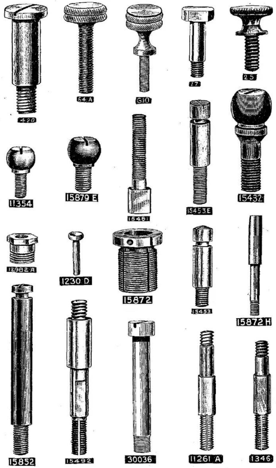
Plate 8—Full Size


Specify Gauge


natural_image
Illustration of a cylindrical object with a central hole and textured surface, labeled '2338' below (no other text or symbols)
Plate 10—Full Size


natural_image
Simple line drawing of a handle-like object with a circular end and central hole, labeled '15835 D' below (no other text or symbols)
natural_image
Illustration of a metal clamp with two loop handles and a central oval hole (no text or symbols)
natural_image
Illustration of a paperclip with a loop handle, labeled '15435 G' (no other text or symbols)
natural_image
Simple line drawing of a hook or connector (no text or symbols)
natural_image
Illustration of a U-shaped metal object with engraved markings, no readable text or symbols present.

natural_image
Simple line drawing of a U-shaped object with no text or symbols
natural_image
Illustration of a sword with two circular holes, no text or symbols present


natural_image
Illustration of a pointed, segmented object with a circular top and central hole, labeled with the number 12954 below (no other text or symbols)Plate 11—Full Size

natural_image
Close-up of a cylindrical object with textured surface and rounded ends, no visible text or symbols14544

natural_image
Illustration of a mechanical part with a triangular tip and circular hole (no text or symbols)15849 A

natural_image
Abstract curved line drawing with vertical striations (no text or symbols)15870A

15849 D

natural_image
Illustration of a curved, segmented object resembling a tool or blade (no text or symbols visible)15870 D

natural_image
Simple line drawing of a bent tool or tool with no text or symbols
15849 E

natural_image
Technical line drawing of a mechanical tool or bracket (no text or symbols)15867 D


15867B
Plate 12—Full Size


natural_image
Illustration of a mechanical pulley or clamp mechanism (no text or symbols)15437A
Piate 13—Full Size

natural_image
Illustration of a mechanical tool with two circular components, no text or symbols present
natural_image
Close-up of a mechanical gear or cam component with concentric rings and central bore (no visible text or symbols)7945

12983

15447 L

natural_image
Technical drawing of a mechanical bracket component (no text or symbols visible)15867 G

natural_image
Technical line drawing of a mechanical component with no visible text or symbols15860

natural_image
Illustration of a wooden mechanical component with two circular holes and four oval openings (no text or symbols)15447K

15458 M

natural_image
Technical line drawing of a T-shaped mechanical component with three circular holes (no text or symbols)15858 L

natural_image
Technical line drawing of a mechanical linkage component (no text or symbols)2334

natural_image
Illustration of a mechanical linkage component (no text or symbols)15446D
Plate 14—Full Size

natural_image
Illustration of a wooden object with a circular hole and horizontal stripes (no text or symbols)21225-7/32

natural_image
Technical line drawing of a mechanical component (no text or symbols)15498 N

natural_image
Illustration of a mechanical component with a curved base and two slots (no text or symbols)23322A

natural_image
Abstract 3D geometric shapes with striped patterns and circular cutouts (no text or symbols)15953

15935 G

15875

15454

15431

natural_image
Close-up of a wooden electrical switch with two circular components (no visible text or symbols)15447 F

natural_image
Illustration of a wooden block with four circular holes (no text or symbols)15852B

natural_image
Illustration of a wooden mechanical component with four circular ports (no text or symbols)15498 V

natural_image
Technical illustration of a mechanical component with three circular holes and a central hub (no text or symbols)15898 F


15854B
Plate 16—One-half Size

15867F

58

364

15850

9932

15885

15874

natural_image
Cross-sectional view of a curved wooden plank or sheet (no text or symbols visible)15435 M

natural_image
Pure electrical circuit lines without any symbols15835B

natural_image
Close-up of a textured metallic surface with two circular holes and a central hole (no text or symbols)15835

natural_image
Cross-sectional view of a mechanical component with hatched texture and mounting holes (no visible text or symbols)15835A
Plate 17—One-half Size

natural_image
Pure electrical circuit lines without any symbols15930

natural_image
Illustration of a door with two circular buttons and horizontal stripes (no text or symbols)15930A

2.A.

23322 L

23322B

23322 P

23322J
Specify
Gauge

23322C

23322 S

23322N
Specify
Gauge

natural_image
Simple black L-shaped bracket or tool (no text or symbols)24

natural_image
Illustration of vintage portable radio equipment with no visible text or symbols23377
Plate 18—One-half Size

natural_image
Technical drawing of a wooden mechanical bracket with four circular holes (no text or symbols)15802

natural_image
Technical line drawing of a wooden right-angle bracket with mounting holes (no text or symbols)15858M

natural_image
Cross-sectional diagram of a wooden plank with three circular holes and hatched material (no text or labels)15458

natural_image
Illustration of a wooden right-handled bracket with measurement markings (no text or symbols)15858 N

natural_image
Technical drawing of a mechanical part with two circular holes and striped surface (no text or symbols)213870

natural_image
Illustration of a mechanical component with a curved top and base, labeled 15866 (no text or symbols on the diagram itself)
natural_image
Illustration of a layered geological or structural structure with no visible text or symbols15858 B

natural_image
Cross-sectional view of a mechanical part with hatched shading and cutouts (no text or symbols)15858C


Plate 21—One-half Size

natural_image
Technical illustration of a mechanical linkage component (no text or symbols)
natural_image
Technical illustration of a mechanical linkage component (no text or symbols)

natural_image
Microscopic view of a layered material sample with horizontal striations and a central circular feature (no text or symbols)
natural_image
Illustration of a mechanical pulley or wheel component (no text or symbols visible)
natural_image
Illustration of a mechanical bolt with threaded shaft and flange (no text or symbols)

natural_image
Technical line drawing of a mechanical component with threaded shaft and flange (no text or symbols)Plate 22—One-half Size

13214

15814

15878 D

15878 E

15878

43C

15806

2306

6038

6039

1230·A

20131B

natural_image
Technical line drawing of a mechanical flange component (no text or symbols)15430 M

natural_image
Technical illustration of a piston mechanism (no text or labels)15879 A

natural_image
Technical illustration of an internal combustion engine piston (no text or labels)15879

natural_image
Technical illustration of a mechanical component with no visible text or symbols15434

natural_image
Technical drawing of a mechanical component with symmetrical grooves and central hole (no text or symbols)15865

natural_image
Technical drawing of a mechanical component with concentric circular features and a flanged end (no text or symbols)15834

natural_image
Technical line drawing of a mechanical bearing assembly (no text or symbols)29130C

Plate 24—One-half Size

natural_image
Technical illustration of a T-shaped mechanical component with threaded base (no text or symbols)21681

natural_image
Technical drawing of a mechanical part with two circular holes and a stepped base (no text or symbols)15868A

15862

15876

15880A

15872G

15872E

21104 E

natural_image
Cylindrical object with vertical striations, no visible text or symbols213558.

natural_image
Illustration of a cylindrical object with vertical striations, no text or symbols present21355

natural_image
Cylindrical object with parallel grooves, no visible text or symbols21355 A

21104 C
Plate 25—One-half Size

natural_image
Illustration of a curved, elongated object with textured surface and small circular end (no text or symbols)15459

natural_image
Technical line drawing of a mechanical component with no visible text or symbols415 B

154966

natural_image
Illustration of a mechanical component with concentric rings and central holes (no text or symbols)15421

natural_image
Pure mechanical part diagram without any text, numbers, or symbols419A

11G

15458 A
natural_image
Illustration of a curved, textured object resembling a tool or tool (no text or symbols visible)118B

15995

15855A
natural_image
Technical line drawing of a mechanical component with threaded ends and central hub (no text or symbols)1275A
Plate 26—One-third Size

Plate 27—One-fourth Size


5157

natural_image
Technical illustration of a curved mechanical component with mounting base (no text or symbols)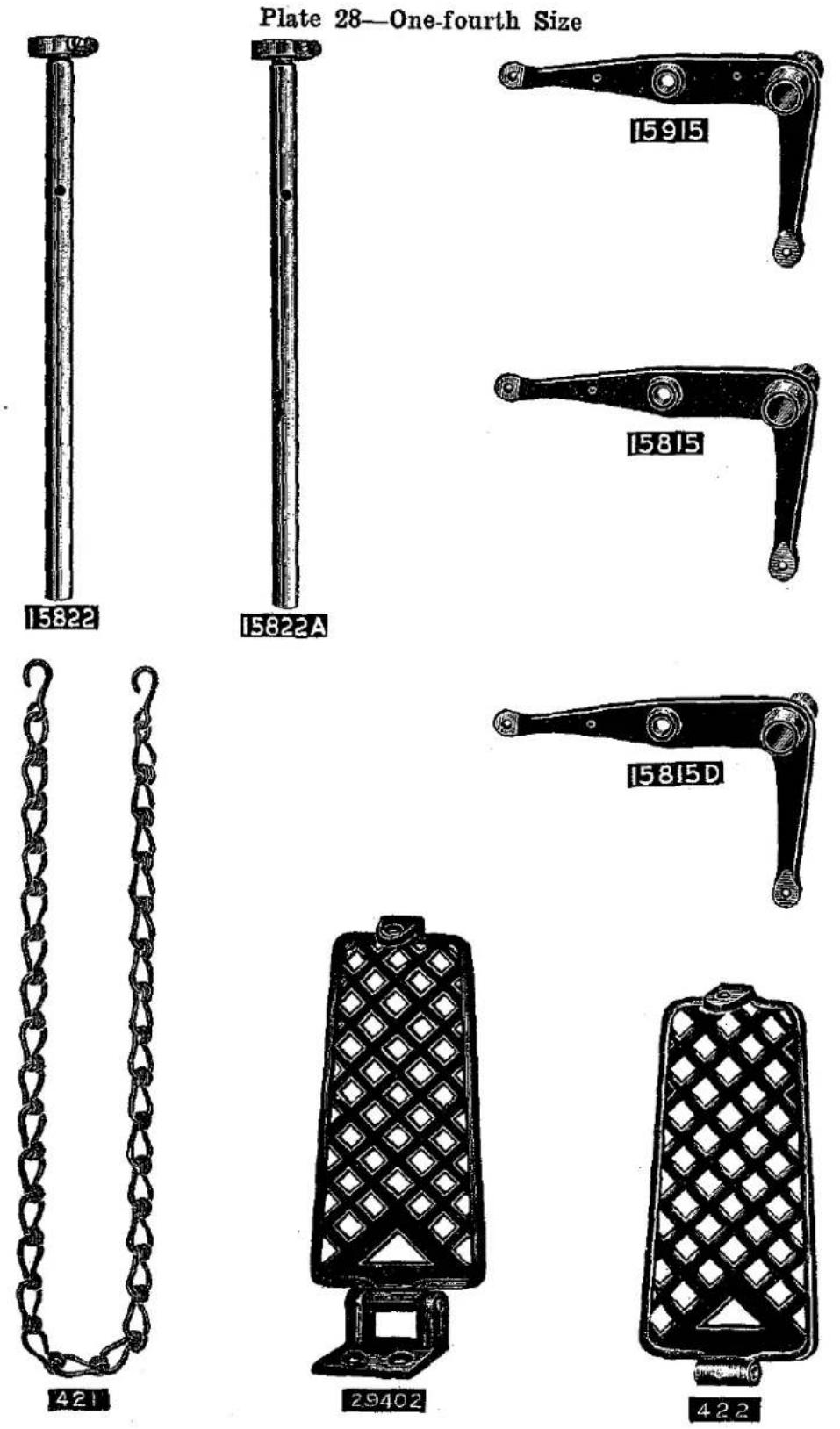


LIST OF PARTS
| Symbol to Order by | The figures in the last column refer only to the plates illustrating the parts, and are not to be used in ordering. Refer to pink insert for prices. | Plate No. |
| 2 A | Cloth Plate Slide, left, for styles in Classes 13200, 15800; also for Styles 15900 A, 15900 E. | 17 |
| 4 E | Cast-off Wire, for Style 15800 E. Obsolete—Present Assembly includes Nos. 15904 and 101 V. | - |
| 4 V | Cast-off Wire, for Styles 13200 A, 15800 A, 15800 B, 15800 D. Obsolete—Present assemblies include Nos. 15904 and 101 V. | 11 |
| Cast-off Wire Screw No. 87. | ||
| 5 | Main Shaft Collar. | 19 |
| Main Shaft Collar Screws No. 95. | ||
| 7 | Feed Rocker, for styles in Classes 13200, 15900; also for Style 15800 A. | 27 |
| Feed Rocker Screws No. 88. | ||
| 8 | Feed Rocker Shaft, solid, 5316 inches long, hardened and ground, standard diameter .407 inch. | 20 |
| 8-408 | Feed Rocker Shaft, standard diameter plus .001 inch. | - |
| 8-409 | Feed Rocker Shaft, standard diameter plus .002 inch. | - |
| 8-410 | Feed Rocker Shaft, standard diameter plus .003 inch. | - |
| 8-413 | Feed Rocker Shaft, standard diameter plus .006 inch. | - |
| 8-416 | Feed Rocker Shaft, standard diameter plus .009 inch. | - |
| 8-419 | Feed Rocker Shaft, standard diameter plus .012 inch. | - |
| 8-422 | Feed Rocker Shaft, standard diameter plus .015 inch. | - |
| 9 X | Feed Bar, for styles in Class 15900. | 26 |
| Feed Bar Screws No. 88. | ||
| 10 | Feed Bar Prong and Sponge, for styles in Classes 13200, 15900; also for Style 15800 A. | 23 |
| Feed Bar Prong Screws No. 94. | ||
| 10 A | Feed Bar Prong Sponge. | - |
| G10 | Thumb Screw, for holding knives in knife grinders. | 7 |
| 11 | Feed Bar Shaft, solid, 3716 inches long, hardened and ground | 19 |
| G11 | Pulley, for knife grinders. | 21 |
| Pulley Screws No. 98. | ||
| G12 | Pulley Spindle, hardened and ground, for knife grinders.. | 21 |
| Pulley Spindle Clamp Screws No. 136. | ||
| G14 | Pulley Spindle Washer, for knife grinders. | 12 |
| T14 | Lower Knife Clamp Nut, for Styles 15800 D, 15800 E, 15800 G. | 8 |
| 15 | Feed Crank Link, hardened. | 26 |
| Feed Crank Link Screw No. 79. | ||
| G15 | Pulley Spindle Nut, for knife grinders. | 8 |
| 16 | Feed Crank Link Ferrule. | 19 |
| G16 | Emery Wheel, for knife grinders. | 26 |
| 17 | Feed Crank Stud. | 7 |
| 18 | Feed Crank Stud; also for Nos. 6039, 15864. | 8 |
LIST OF PARTS
| Symbol to Order by | The figures in the last column refer only to the plates illustrating the parts, and are not to be used in ordering. Refer to pink insert for prices. | Plate No. |
| 19 | Feed Crank Stud Cap. | 19 |
| Feed Crank Stud Cap Screws No. 77. | ||
| 20 | Feed Crank Stud Washer. | 15 |
| 21 | Feed Crank Link Pin. | 19 |
| Feed Crank Link Pin Set Screw No. 77. | ||
| 24 | Cloth Plate Gauge, for Style 15900 A. | 17 |
| 25 | Screw, for cloth plate gauge. | 7 |
| 25 C | Screw, for cloth plate guard on styles in Class 15900; also for No. 21387 D. | 5 |
| 25 CC | Screw, for binder swinging arm support holder; also for Nos. 23322 J- 34 , 23322 J- 78 , 23322 J-1, 23322 J- 114 | 5 |
| 28 A | Set Screw, headless, for needles on Styles 15800 D, 15800 E, 15800 G. | 5 |
| 33 | Looper Rocker Stud, hardened. | 6 |
| Looper Rocker Stud Nut, No. 15887. | ||
| 41 A | Hand Lifter for Styles 15800 D, 15800 E, 15800 G, 15900 A, 15900 E. | 19 |
| Hand Lifter Stud No. 86. | ||
| 42 A | Hand Lifter Screw Pin, hardened. | 6 |
| 43 | Feed Lift Eccentric, ground, marked F, throw .062 inch for styles in Class 13200, 15900; also for Styles 15800 A, 15800 B. Obsolete-Present assembly specifies No. 43 C. | — |
| 43 C | Feed Lift Eccentric, ground, throw .080 inch, for Styles in Class 13200, 15900; also for Styles 15800 A, 15800 B. | 22 |
| Feed Lift Eccentric Screw No. 96. | ||
| 47 | Needle Lever Stud Nut, hardened. | 8 |
| 48 | Needle Lever Stud Washer. | 15 |
| 52 A | Needle Lever Thread Eyelet, for styles in Class 15800. | 19 |
| Needle Lever Thread Eyelet Screw No. 98 A. | ||
| 53 A | Needle Bar Thread Eyelet. | 19 |
| Needle Bar Thread Eyelet Screw No. 605 A. | ||
| 54 | Needle Bar Link, hardened. | 19 |
| 56 | Needle Clamp Nut, hardened. | 20 |
| 58 | Looper Thread Nipper Spring, rear. | 16 |
| Looper Thread Nipper Spring Screw No. 22542. | ||
| 61 X | Presser Bar Connection. | 19 |
| Presser Bar Connection Screw, front, No. 89. | ||
| Presser Bar Connection Screw, rear, No. 77. | ||
| 62 | Presser Guide Bar, hardened and ground, standard diameter, .319 inch. | 19 |
| 62-322 | Presser Guide Bar, standard diameter plus .003 inch. | — |
| 62-325 | Presser Guide Bar, standard diameter plus .006 inch. | — |
| 62-328 | Presser Guide Bar, standard diameter plus .009 inch. | — |
| 62-331 | Presser Guide Bar, standard diameter plus .012 inch. | — |
| 62-334 | Presser Guide Bar, standard diameter plus .015 inch. | — |
LIST OF PARTS
| Symbol to Order by | The figures in the last column refer only to the plates illustrating the parts, and are not to be used in ordering. Refer to pink insert for prices. | Plate No. |
| 64 | Presser Spring Rest. | 19 |
| Presser Spring Rest Screw No. 88. | ||
| 64 A | Presser Spring Regulating Screw; also for knife grinders. | 7 |
| 64 B | Presser Spring Regulating Screw Lock Nut; also for knife grinders. | 8 |
| 69 S | Thread Stand Pin, 4 inches long; for Style C stand. | 30 |
| ∠□69 FD | Set Screw, square head, cup point, 416 inch diameter, 18 threads, 58 inch long, for Style C thread stand seats. | 6 |
| 73 A | Screw, for looper needle guards; also for Nos. 15435 N, 15435 P. | 5 |
| 75 | Clamp Screw, for upper knife on Styles 15800 D, 15800 E, 15800 G. | 6 |
| 75 A | Screw, for knife eccentric connection; also for Nos. 15865, 15879, 15879 A. | 6 |
| 77 | Screw, for lower needle bar link pin on Styles 13200 A, 15800 A, 15800 B, 15900 A, 15900 D, 15900 E; also for Nos. 19, 21, 61 X, 7945, 12983 | 5 |
| 77 A | Screw, for feed bar needle rear guard on Style 15800 B; also for No. 15847 A. | 5 |
| 78 | Screw, upper, for needle bar link pin. | 5 |
| 79 | Screw, for feed crank link | 6 |
| 81 | Spot Screw, for needle lever eccentricities; also for No. 15498 J. | 5 |
| 82 | Screw, for regulating length of stitch. | 6 |
| 84 A | Stitch Regulating Ferrule, for styles in Class 13200, 15900; also for Styles 15800 A, 15800 B. | 8 |
| 86 | Stud, for hand lifters; also or Nos. 15498 N, 15868 A, 23322 C. | 6 |
| 86 A | Screw, plus size, for hand lifters, tap No. V113. | 6 |
| 87 | Screw, for throat plates; also for Nos. 4 E, 4 V, 196, 196 D, 15802, 15904. | 5 |
| 87 U | Screw, for binder on Styles 13200 A, 15800 A, 15800 B; also for No. 23322 A. | 5 |
| 88 | Set Screw, headless, for feed rockers; also for Nos. 9 X, 64, 161, 5142, 12865, 15437 A, 15847, 15847 E, 15862, 21113 B. | 5 |
| 88 B | Set Screw, headless, concave end, for needles on Style 13200 A. | 5 |
| 89 | Spot Screw, for take-ups; also for Nos. 13218-2, 13218-4. | 5 |
| 90 | Screw, for take-up thread eyelet; also for Nos. 15447 K, 15454, 15857, 23322 L. | 5 |
| 91 | Clamp Screw, fillister head, for presser feet; also for No. 15867 F. | 5 |
| 91 A | Screw, for knife guard on Styles 15800 D, 15800 E; also for Nos. 15857, 15881 D. | 5 |
∠□ See page 25.
LIST OF PARTS
| Symbol to Order by | The figures in the last column refer only to the plates illustrating the parts, and are not to be used in ordering. Refer to pink insert for prices. | Plate No. |
| 93 | Screw, 7/16 inch long, for cast-off wire bracket; also for Nos. 15447 F, 15447 J, 15451, 15847 C, 15871 D, 15872 G, 15876, 15905 A, 15905 D. | 6 |
| 93 A | Screw, 9/37 inch long, for lifter lever extension; also for No's. 13205, 15805 F, 15835, 15835 A, 15498 H, 15847 A.. | 6 |
| 94 | Screw, for feed bar prongs; also for Nos. 5125, 9932, 13225, 15435 G, 15447 J, 15493 A, 15835 B, 15838 A. | 6 |
| 95 | Set Screw, for needle lever eccentricis; also for Nos. 5, 100 B, 336, 15493 B, 15878, 15878 D, 15878 E, 21113 A. | 5 |
| 96 | Spot Screw, for feed lift eccentricis; also for Nos. 13214, 15814, 15878, 15880 A. | 5 |
| 97 | Screw, for supporting feed dogs on non-differential feed machines; also for Nos. 2334, 15860, 15872 B, 15872 L.. | 6 |
| 97 A | Screw, for looper connecting rod ball joints; also for No. 15865. | 6 |
| 98 | Set Screw, for knife grinder pulley; also for Nos. 267, 424, 482. | 5 |
| 98 A | Screw, for needle lever thread guides; also for No. 15496 B.. | 5 |
| ∠100 B | Thread Stand Wire, 16 inches long, for Style C thread stand. | 27 |
| Thread Stand Wire Screw, 32 threads to inch, No. 95. Thread Stand Wire Screw, 24 threads to inch, No. 22813. | ||
| 101 | Take-up, for looper thread. Obsolete-Present assemblies include Nos. 101 V and 15904. | 26 |
| 101 V | Take-up, for looper thread. | 26 |
| Take-up Screw No. 89. | ||
| 107 | Tension Spring Ferrule. | 8 |
| 108 | Tension Nut. | 8 |
| 109 | Tension Disc, hardened and lapped. | 12 |
| V109 | Tap, marked "J2" for No. 22526. | 15 |
| V113 | Tap, marked "Q2" for No. 86 A. | 15 |
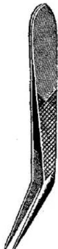
| 116 | Wrench, 9/32 inch, hardened, for needle clamp nut. | 25 |
| 118 B | Thread Tweezers. | 25 |
| V118 | Tap, marked "X2" for No. 22521. | 15 |
| 134 | Screw, for binding cutter lower knife. | 6 |
| 136 | Screw, for looper rock shaft frame; also for Nos. G12, 15498 J, 15850 B, 15873, 15873 A. | 6 |
| 161 | Binding Holder Disc Supporting Collar. | 8 |
| Binding Holder Disc Supporting Collar Screw No. 88. | ||
| 176 | Looper, front, with guard, for Style 13200 A. | 2 |
| 176 B-2 | Looper, back, for No. 2 gauge Style 13200 A. | 2 |
| 176 B-4 | Looper, back, for No. 4 gauge, Style 13200 A. | 2 |
| Looper Set Screw No. 22565. | ||
| 179 | Looper Needle Guard, marked "E", for looper No. 176.. | 12 |
| Looper Needle Guard Screw No. 73 A. |
∠ See page 25.
LIST OF PARTS
| Symbol to Order by | The figures in the last column refer only to the plates illustrating the parts, and are not to be used in ordering. Refer to pink insert for prices. | Plate No. |
| 181 | Looper Rocker, hardened, for styles in Class 15900; also for Styles 15800 A, 15800 B, 15800 E, 15800 G. | 26 |
| 182 | Looper Rocker, hardened, for Style 13200 A. | 26 |
| 187 A | Screw, for looper thread guide on Styles 15800 D, 15800 E, 15800 G; also for Nos. 15858 M, 15858 N, 15881 A. | 5 |
| 196 | Throat Plate Needle Rear Guard, hardened, marked “F”, for Style 15900 A. | 1 |
| 196 D | Throat Plate Needle Rear Guard, hardened, marked “AE”, for Styles 15900 D 15900 E. | 1 |
| Throat Plate Needle Rear Guard Screw No. 87. | ||
| 213 | Looper Rocker, hardened, for Style 15800 D. | 26 |
| 223 C | Screw, for binding cutter upper knife. | 6 |
| 258 | Upper Knife Lever Ball Nut. | 8 |
| 267 | Collar, for knife grinder swinging frame pivot pin. | 8 |
| 269 | Looper Connecting Rod Nut, left thread. | 8 |
| 330 A | Main Shaft Sleeve, 1964 inch long, for Styles 13200 A 15800 A, 15800 B. | 19 |
| 336 | Tension Thread Eyelet, for styles in Classes 15800, 15900.. | 10 |
| Tension Thread Eyelet Screw No. 95. | ||
| 337 | Tension Thread Eyelet, one eye; Obsolete—Replaced by No. 336. | 10 |
| 364 | Looper Thread Nipper Spring, front. | 16 |
| Looper Thread Nipper Spring Screw No. 22542. | ||
| 380 | Cloth Plate Extension Spring Latch, for styles in Class 15900; also for Styles 15800 E, 15800 G. | 9 |
| Cloth Plate Extension Spring Latch Screw No. 22564 A. | ||
| 413 | Oil Can, with spout. | 30 |
| 413 A | Oil-Can Spout. | — |
| 415 B | Lifter Lever Casting. | 25 |
| 419 A | Lifter Lever Extension. | 25 |
| Lifter Lever Extension Screws No. 93 A. | ||
| 420 | Lifter Lever Stud. | 7 |
| 421 | Lifter Lever Chain. | 28 |
| 422 | Lifter Treadle. | 28 |
| 423 | Lifter Treadle Rest. | 23 |
| 424 | Lifter Treadle Pin. | 19 |
| Lifter Treadle Pin Set Screw, 32 threads to inch, No. 98. | ||
| Lifter Treadle Pin Set Screw, 24 threads to inch, No. 22813. | ||
| 426 | Lifter Lever Spring. | 9 |
| 426 A | Lifter Lever Spring Pin. | 15 |
| 482 | Upper Knife Bar Shaft Collar, for Styles 13200 A, 15800 A; also feed rocker shaft collar for Styles 15800 D, 15800 E, 15800 G. | 19 |
LIST OF PARTS
| Symbol to Order by | The figures in the last column refer only to the plates illustrating the parts, and are not to be used in ordering. Refer to pink insert for prices. | Plate No. |
| Y502-319 | Expansion Reamer, for presser bar and presser guide bar size .319 inch. | 29 |
| Y502-322 | Expansion Reamer, size .322 inch. | — |
| Y502-325 | Expansion Reamer, size .325 inch. | — |
| Y502-328 | Expansion Reamer, size .328 inch. | — |
| Y505-407 | Expansion Reamer, for feed rocker shafts and feed bar shaft, size .407 inch. | 29 |
| Y505-410 | Expansion Reamer, size .410 inch. | — |
| Y505-413 | Expansion Reamer, size .413 inch. | — |
| Y505-416 | Expansion Reamer, size .416 inch. | — |
| Y506-530 | Expansion Reamer, for main shafts, size .530 inch. | 29 |
| Y506-533 | Expansion Reamer, size .533 inch. | — |
| Y506-536 | Expansion Reamer, size .536 inch. | — |
| Y510-200 | Expansion Reamer, for needle bars, size .200 inch. | — |
| 531 | Set Screw, for binder swinging arm support. | 5 |
| 540 | Frame Thread Eyelet Guide Pin. | 15 |
| 604 | Screw, for presser foot extension on No. 15820 D. | 5 |
| 605 | Screw, for yielding side spring Nos. 15882, 15882 A 19146 A; also for No. 15930 A. | 5 |
| 605 A | Screw, for needle bar thread eyelet. | 5 |
| 727 | Looper, with guard for Styles 15800 D, 15800 E, 15800 G. | 2 |
| 727 A | Looper, without guard, otherwise same as No. 727. | 2 |
| Looper Set Screw No. 22565. | ||
| 729 | Looper Needle Guard, marked “Q”, for loopers Nos. 727, 15807, 15907. | 12 |
| Looper Needle Guard Screw No. 73 A. | ||
| Y800 | Taper Reamer, for lever end of needle lever stud. | — |
| Y801 | Taper Reamer, for frame end of needle lever stud. | — |
| Y802 | Taper Reamer, for needle bar link pins and feed crank link pins. | 29 |
| 892 | Upper Knife Bar Shaft, for Styles 13200 A, 15800 A, 15800 B. | 20 |
| †1230 A | Needle Lever Connection Upper Bearing. | 22 |
| Needle Lever Connection Upper Bearing Screws No. 22587. | ||
| 1230 B | Needle Lever Connection Bearing Valve Spring. | 9 |
| Needle Lever Connection Bearing Valve Spring Screw No. 22586 A. | ||
| 1230 C | Needle Lever Connection Tube. | 19 |
| Needle Lever Connection Tube Nut, left thread, No. 15430 C. | ||
| Needle Lever Connection Tube Nut, right thread, No. 15430 D. | ||
| 1230 D | Needle Lever Connection Bearing Valve. | 7 |
| 1275 A | Needle Lever Stud, standard diameter. | 25 |
‡ See page 25.
LIST OF PARTS
| Symbol to Order by | The figures in the last column refer only to the plates illustrating the parts, and are not to be used in ordering. Refer to pink insert for prices. | Plate No. |
| 1275 E | Needle Lever Stud, plus size on frame section, viz.; .001, .002, .003, .006, .012, .018 inch; specify plus amount. Example; 1275 E-003 represents a stud plus .003 inch on frame section. | — |
| 1275 F | Needle Lever Stud, plus size on lever section, viz.; .001, .002, .003, .006 inch; specify plus amount. Example; 1275 F-003 represents a stud .003 inch on lever section. | — |
| 1275 H | Needle Lever Stud, plus size equal on each section; viz.; .001, .002, .003, .006 inch; specify plus amount. Example; 1275 H-003 represents a stud plus .003 inch on each section. | — |
| 1275 J | Needle Lever Stud, plus size unequal on each section, viz. (.001, .002) (.001, .003) (.001, .006) (.002, .001) (.002, .003) (.002, .006) (.003, .001) (.003, .002) (.003, .006) (.006, .001) (.006, .002) (.006, .003) (.012, .001) (.012, .002) (.012, .003) (.012, .006) (.018, .001) (.018, .002) (.018, .003) (.018, .006) Specify plus amounts, arranged frame section first and lever section last. Examples; 1275 J-003-006 represents a stud plus .003 inch on frame section and .006 inch on lever section, 1275 J-006-003 represents a stud plus .006 inch on frame section and .003 inch on ever section. Needle Lever Stud Screw No. 22586. Needle Lever Stud Felt No. 15430 L. Note: Before lapping the bearing of a needle lever and a needle lever stud remove the felt from the stud and replace it after the lapping compound has been washed out. | — |
| 1286 | Needle Lever Link Pin Assembly, internal oiling, hardened and ground, includes one each Nos. 1286 A, 1286 B, 12964 C, 22560; also for Nos. 15446 D, 15872 B. | 8 |
| 1286 A | Needle Lever Link Pin...... Needle Lever Link Pin Set Screw, upper, No. 77. Needle Lever Link Pin Set Screw, lower, No. 78. Needle Lever Link Pin Ball No. 12964 C. | 8 |
| 1286 B | Needle Lever Link Pin Ball Spring...... Needle Lever Link Pin Ball Spring Screw No. 22560. | 9 |
| 1346 | Tension Post, length over all 1116 inches, for style 13200 A.. | 7 |
| 1347 | Tension Post Ferrule, hardened, length over all 516 inch, for Style 13200 A. | 8 |
| 1349 A-0 | Tension Spring, .016 inch diameter wire, for looper thread, on styles in Classes 13200, 15800. | 9 |
| 1349 A-3 | Tension Spring, .028 inch diameter wire, for looper thread, on styles in Class 15900; also for needle thread on Styles 15800 D, 15800 E, 15800 G. | 9 |
LIST OF PARTS
| Symbol to Order by | The figures in the last column refer only to the plates illustrating the parts, and are not to be used in ordering. Refer to pink insert for prices. | Plate No. |
| 1349 A-4 | Tension Spring, .036 inch diameter wire, for needle thread on styles in Classes 13200, 15900; also for Styles 15800 A, 15800 B. | 9 |
| 1361 A | Presser Spring Pin, length over all 38 inch. | 15 |
| 1362 | Main Shaft Sleeve Pin, length over all 112 inches. | 15 |
| 1588 | Cloth Plate Swinging Extension Spring Latch, for Style 15800 D. | 9 |
| Cloth Plate Swinging Extension Spring Latch Screw No. 22564 A. | ||
| 2306 | Feed Lift Eccentric, ground, for Styles 15800 E, 15800 G. | 22 |
| Feed Lift Eccentric Screw No. 96. | ||
| 2324 Q | Throat Plate, for Style 15800 G. | 2 |
| Throat Plate Screw No. 87. | ||
| 2327 | Presser Foot, for Style 15800 G. | 3 |
| Presser Foot Screw No. 91. | ||
| 2333 | Feed Bar Prong and Sponge, for Styles 15800 D, 15800 E, 15800 G. | 23 |
| Feed Bar Prong Screws No. 94. | ||
| 2334 | Differential Feed Bar Link, for Styles 15800 D, 15800 E, 15800 G. | 13 |
| Differential Feed Bar Link Screws No. 97. | ||
| 2335 | Differential Feed Bar, for Styles 15800 D, 15800 E, 15800 G. | 23 |
| 2338 | Main Shaft Sleeve, 114 inches long, for styles in Class 15900; also for Styles 15800 D, 15800 E, 15800 G. | 8 |
| 4517 | Needle Bar, hardened and ground, for styles in Class 15900; also for Styles 15800 A, 15800 B. | 20 |
| 5125 | Feed Bar Needle Rear Guard, hardened, marked “AJ” for Style 15800 A. | 1 |
| Feed Bar Needle Rear Guard Screw No. 94. | ||
| 5142 | Feed Bar, for Styles 13200 A, 15800 A. | 26 |
| Feed Bar Screws No. 88. | ||
| 5143 | Differential Feed Bar, for Style 15800 B. | 26 |
| 5144 | Differential Feed Bar Link Stud Nut. | 8 |
| 5156 | Feed Rocker, for Style 15800 B. | 27 |
| Feed Rocker Screws No. 88. | ||
| 5157 | Feed Rocker Connection. | 27 |
| Feed Rocker Connection Screws No. 22548. | ||
| 6038 | Looper Connecting Rod Ball Joint Assembly, left. | 22 |
| 6039 | Looper Connecting Rod Ball Joint Assembly, right. | 22 |
| Looper Connecting Rod Ball Joint Screws No. 97 A. | ||
| Looper Connecting Rod Ball Stud Nut No. 18. | ||
| 6427 J | Presser Foot, for Style 15900 E. | 3 |
| 6520 | Presser Foot, for Style 15900 A. | 3 |
| Presser Foot Clamp Screw No. 91. |
LIST OF PARTS
| Symbol to Order by | The figures in the last column refer only to the plates illustrating the parts, and are not to be used in ordering. Refer to pink insert for prices. | Plate No. |
| 7945 | Looper Rocker Cone | 13 |
| Looper Rocker Cone Screws No. 77. | ||
| 9224 E | Throat Plate, for Style 15900 A | 2 |
| Throat Plate Screws No. 87. | ||
| 9932 | Feed Bar Shoe, for styles in Classes 13200, 15900; also for Styles 15800 A, 15800 D, 15800 E, 15800 G | 16 |
| Feed Bar Shoe Screw No. 94. | ||
| 11261 A | Tension Post, length over all 178 inches. Obsolete—Replaced by Nos. 1346, 1347, 13148 A–20 and 35582 B... | 7 |
| 11261 B | Tension Post Ferrule, length over all 3164 inch. Obsolete—Replaced by Nos. 1347, 1346, 13148 A–20 and 35582 B.. | 8 |
| 11354 | Looper Eccentric Connection Ball, hardened | 7 |
| 11755 | Hand Lifter, for style 15900 D | 19 |
| Hand Lifter Stud No. 86. | ||
| 12865 | Presser Spring Rest Support Collar | 8 |
| 12934 A | Looper Eccentric Connection Ball Stud Nut; also for No. 23322 S. | 8 |
| 12954 | Tension Thread Eyelet, one eye, 168 inches long. Obsolete—Replaced by No. 336 | 10 |
| 12957 E | Binder Swinging Arm Stud Spring Washer | 15 |
| 12964 C | Needle Lever Link Pin Ball | 15 |
| 12982 | Knife Bar Locking Handle Nut, for Styles 13200 A, 15800 A, 15800 B | 8 |
| 12982 A | Knife Bar Locking Bolt Threaded Bushing, for Styles 13200 A, 15800 A, 15800 B | 7 |
| 12983 | Knife Bar Locking Handle | 13 |
| Knife Bar Locking Handle Screw No. 77. | ||
| 12984 | Knife Bar Locking Handle Stop Pin, for Styles 13200 A, 15800 A, 15800 B | 15 |
| 12986 B | Screw, for binding guard on Styles 13200 A, 15800 A, 15800 B | 5 |
| 13148 A–20 | Tension Post Elongating Stud, 58 inch increment, for styles in Class 13200 | 6 |
| 13205 | Feed Dog, for Style 13200 A | 4 |
| Feed Dog Screw No. 93 A. | ||
| 13214 | Looper Eccentric, hardened and ground, for Style 13200 A | 22 |
| Looper Eccentric Screw No. 96. | ||
| 13217–2 | Needle Bar, hardened and ground, for No. 2 gauge, Style 13200 A | 20 |
| 13217–4 | Needle Bar, hardened and ground, for No. 4 gauge, Style 13200 A | 20 |
| Needle Bar Set Screws No. 88. | ||
| 13218–2 | Needle Clamp Collar, for No. 2 gauge, Style 13200 A | 8 |
LIST OF PARTS
| Symbol to Order by | The figures in the last column refer only to the plates illustrating the parts, and are not to be used in ordering. Refer to pink insert for prices. | Plate No. |
| 13218-4 | Needle Clamp Collar, for No. 4 gauge, Style 13200 A.... | 8 |
| Needle Clamp Collar Screw No. 89. | ||
| Needle Set Screw No. 88 B. | ||
| 13220-2 | Presser Foot, for No. 2 gauge, Style 13200 A.... | 3 |
| Presser Foot Clamp Screw No. 91. | ||
| Presser Foot Yielding Side Spring No. 19146 A. | ||
| Presser Foot Yielding Side Spring Screw No. 605. | ||
| 13220 A-4 | Presser Foot, for No. 4 gauge, Style 13200 A.... | 3 |
| Presser Foot Clamp Screw No. 91. | ||
| Presser Foot Yielding Side Spring No. 15882. | ||
| Presser Foot Yielding Side Spring Screw No. 605. | ||
| 13224 A-2 | Throat Plate, for No. 2 gauge, Style 13200 A.... | 2 |
| 13224 A-4 | Throat Plate, for No. 4 gauge, Style 13200 A.... | 2 |
| Throat Plate Screws No. 87. | ||
| 13225 | Feed Bar Needle Rear Guard, for Style 13200 A.... | 1 |
| Feed Bar Needle Rear Guard Screw No. 94. | ||
| 13254 | Take-up Thread Eyelet, for looper thread of Style 13200 A | 10 |
| Take-up Thread Eyelet Screw No. 90. | ||
| 14076 | Stud, for take-up thread eyelet holder.... | 6 |
| 14544 | Differential Feed Bar Shaft, hardened and ground, 3216 inches long for Styles 15800 B, 15800 D, 15800 E 15800 G.... | 11 |
| 15421 | Pulley.... | 25 |
| Pulley Screws No. 22597. | ||
| 15430 C | Needle Lever Connection Tube Nut, left thread.... | 8 |
| 15430 D | Needle Lever Connection Tube Nut, right thread.... | 8 |
| 15430 L | Needle Lever Connection Oil Retaining Felt; also for Nos. 1275 A, 1275 E, 1275 F, 1275 H, 1275 J.... | 19 |
| $15430 M | Needle Lever Connection Lower Bearing.... | 22 |
| Needle Lever Connection Lower Bearing Screws No. 22587. | ||
| 15431 | Needle Lever Washer, wood fibre.... | 14 |
| 15432 | Needle Lever Ball, hardened.... | 7 |
| 15433 | Needle Lever Ball Nut.... | 8 |
| 15434 | Needle Lever Eccentric and Balance Weight, formerly marked "BM", for styles in Class 15900; also for 13200 A, 15800 A, 15800 B, 15800 E, 15800 G.... | 22 |
| Needle Lever Eccentric Spot Screw No. 81. | ||
| Needle Lever Eccentric Set Screw No. 95. | ||
| 15435 G | Frame Needle Thread Controller Guide, adjustable for styles in Class 15800.... | 10 |
| Frame Needle Thread Controller Guide Screw No. 94. | ||
| 15435 M | Balance Weight Guard, for use with thread eyelet No. 15435 N. Obsolete.... | 16 |
† See page 25.
LIST OF PARTS
| Symbol to Order by | The figures in the last column refer only to the plates illustrating the parts, and are not to be used in ordering. Refer to pink insert for prices. | Plate No. |
| 15435 N | Balance Weight Guard Thread Eyelet, for Style 13200. Obsolete.... | 10 |
| Balance Weight Guard Thread Eyelet Screw No. 73 A. | ||
| 15435 P | Balance Weight Guard Thread Eyelet Support, for Style 13200. Obsolete.... | 15 |
| Balance Weight Guard Thread Eyelet Support Screws No. 73 A. | ||
| 15436 | Renewable Bearing, for needle bar.... | 8 |
| Renewable Bearing Clamp Screw No. 22569. | ||
| 15437 A | Needle Bar Connection Assembly, one each Nos. 15438 C, 15438 D, 15438 H, 15438 J, and two No. 15438 B.... | 13 |
| 15438 B | Needle Bar Thread Nipper Disc, hardened.... | 12 |
| 15438 C | Needle Bar Thread Nipper Disc Spring.... | 9 |
| 15438 D | Needle Bar Thread Nipper Stud.... | 6 |
| 15438 H | Needle Bar Connection.... | 19 |
| 15438 J | Needle Bar Thread Nipper Guide.... | 19 |
| 15446 C | Differential Feed Bar Link Stud.... | 6 |
| 15446 D | Differential Feed Bar Link, for Style 15800 B.... | 13 |
| Differential Feed Bar Link Screw No. 22743. | ||
| 15447 F | Feed Bar Shoe, hardened and ground, for Style 15800 B.. | 14 |
| Feed Bar Shoe Screw No. 93. | ||
| 15447 G | Feed Bar Prong and Sponge, for Style 15800 B.... | 23 |
| Feed Bar Prong Screws No. 94. | ||
| 15447 K | Differential Feed Bar Guide, upper, for-Style 15800 B.... | 13 |
| Differential Feed Bar Guide Screws No. 90. | ||
| 15447 L | Differential Feed Bar Guide, lower.... | 13 |
| Differential Feed Bar Guide Screw, front, No. 93. | ||
| Differential Feed Bar Guide Screw, rear, No. 94. | ||
| 15448 | Presser Bar, hardened and ground, standard diameter .319 inch.... | 20 |
| 15448-322 | Presser Bar, standard diameter plus .003 inch.... | — |
| 15448-325 | Presser Bar, standard diameter plus .006 inch.... | — |
| 15448-328 | Presser Bar, standard diameter plus .009 inch.... | — |
| 15448-331 | Presser Bar, standard diameter plus .012 inch.... | — |
| 15448-334 | Presser Bar, standard diameter plus .015 inch.... | — |
| 15451 | Lower Knife Clamp, for Styles 13200 A, 15800 A, 15800 B | 12 |
| Lower Knife Clamp Screw No. 93. | ||
| 15453 | Lower Knife Support Adjusting Screw, for Styles 15800 A, 15800 B.... | 7 |
| 15453 E | Lower Knife Support Adjusting Screw, for Style 13200 A.. | 7 |
| 15454 | Lower Knife Support Adjusting Screw Plate, for Styles 13200 A, 15800 B.... | 14 |
| Lower Knife Support Adjusting Screw Plate Screws No. 90. |
LIST OF PARTS
| Symbol to Order by | The figures in the last column refer only to the plates illustrating the parts, and are not to be used in ordering. Refer to pink insert for prices. | Plate No. |
| 15458 | Front Cover Support, for No. 15857.... | 18 |
| Front Cover Support Screws No. 90. | ||
| 15458 A | Front Cover Hinge Pin, for No. 15857.... | 25 |
| 15458 D | Front Cover Diverting Guide Spring, for No. 15857.... | 9 |
| 15458 F | Front Cover Diverting Guide Spring Plate, for No. 15857 | 15 |
| Front Cover Diverting Guide Spring Plate Screws No. 22561. | ||
| 15458 H | Front Cover Locking Pin, for No. 15857.... | 15 |
| 15458 J | Front Cover Locking Pin Spring, for Styles 13200 A, 15800 A, 15800 B.... | 9 |
| 15458 M | Front Cover Diverting Guide Handle Latch, for No. 15857.... | 13 |
| 15459 | Presser Spring.... | 25 |
| 15481 | Knife Bar Locking Bolt, for Styles 13200 A, 15800 A, 15800 B.... | 7 |
| 15491 A | Looper Frame Thread Eyelet. Obsolete.... | 19 |
| 15492 | Tension Post, length over all 235 inches.... | 7 |
| 15493 A | Frame Looper Thread Eyelet, for Style 13200 A.... | 10 |
| Looper Frame Thread Guide Screw No. 94. | ||
| 15496 B | Frame Looper Thread Guide.... | 25 |
| Frame Looper Thread Guide Screw No. 98 A. | ||
| 15498 E | Grinder Head, for knife grinders.... | 21 |
| 15498 G | Grinder Swinging Frame Pivot Pin, hardened and ground | 20 |
| 15498 H | Grinder Swinging Frame Pivot Pin Friction Washer.... | 15 |
| Grinder Swinging Frame Pivot Pin Friction Washer Screw No. 93 A. | ||
| 15498 J | Grinder Swinging Frame Adjusting Sleeve.... | 21 |
| Grinder Swinging Frame Adjusting Sleeve Clamp Screw No. 136. | ||
| Grinder Swinging Frame Adjusting Sleeve Stop Screw No. 81. | ||
| 15498 K | Grinder Swinging Frame Adjusting Thumb Screw.... | 21 |
| 15498 L | Grinder Swinging Frame Stop Pin.... | 19 |
| Grinder Swinging Frame Stop Pin Regulating Screw No. 64 A. | ||
| 15498 N | Grinder Knife Positioning Lever.... | 14 |
| Grinder Knife Positioning Lever Screw No. 86. | ||
| 15498 P | Grinder Dust Guard.... | 21 |
| Grinder Dust Guard Screw No. 22570. | ||
| 15498 V | Grinder Swinging Frame Top Plate, for No. 15898 B.... | 14 |
| Grinder Swinging Frame Top Plate Screws No. 22516. | ||
| 15595 A | Thread Controller Rack, for styles in Class 13200, 15900.. | 13 |
| Thread Controller Rack Screw No. 22519. | ||
| 15595 B | Thread Controller Thread Guide.... | 10 |
LIST OF PARTS
| Symbol to Order by | The figures in the last column refer only to the plates illustrating the parts, and are not to be used in ordering. Refer to pink insert for prices. | Plate No. |
| 15595 F | Needle Lever Thread Guide, for styles in Class 13200, 15900. | 10 |
| Needle Lever Thread Guide Screw No. 98 A. | ||
| 15724 E | Throat Plate, for use in conjunction with main feed dog sections Nos. 15805 D or 15805 J and 15826 A for making 12 inch minimum width of seam on Style 15800 D. | 1 |
| 15801 C | Cloth Plate, for Styles 13200 A, 15800 A, 15800 B. | 30 |
| † 15801 H | Cloth Plate Assembly, for Style 15800 D. | 30 |
| ‡ 15801 K | Cloth Plate Assembly, for Styles 15800 E, 15800 G. | 30 |
| Cloth Plate Screws No. 22574. | ||
| 15802 | Cloth Plate Cover, for Styles 15800 D, 15800 E, 15800 G. | 18 |
| Cloth Plate Cover Screws No. 87. | ||
| 15805 D | Main Feed Dog, for use with throat plate No. 15724 E. | 4 |
| 15805 E | Main Feed Dog, for Styles 15800 E, 15800 G. | 4 |
| Main Feed Dog Screw No. 22585. | ||
| 15805 F | Feed Dog, for Style 15800 A. | 4 |
| Feed Dog Screw No. 93 A. | ||
| 15805 G | Main Feed Dog, for Style 15800 B. | 4 |
| Main Feed Dog Screws No. 22593. | ||
| 15805 J | Main Feed Dog Section, comprising two rows of teeth cut 8 to the inch and shank, for Style 15800 D. | 4 |
| Main Feed Dog Section Screw No. 22585. | ||
| 15805 K | Main Feed Dog Section, comprising one row of teeth cut 22 to inch, for Style 15800 D. | 4 |
| Main Feed Dog Section Screw No. 22716. | ||
| 15806 | Feed Lift Eccentric, ground, marked “DH”, for Style 15800 D. | 22 |
| Feed Lift Eccentric Screw No. 96. | ||
| 15807 | Looper, with guard and closed rear thread eye. Obsolete. | — |
| 15807 D | Looper, with guard and closed rear thread eye. Obsolete. | — |
| Looper Set Screw No. 22565. | ||
| 15814 | Looper Eccentric, hardened, formerly marked “C V”, for styles in Classes 15800 and 15900. | 22 |
| Looper Eccentric Screw No. 96. | ||
| 15815 | Needle Lever, for Styles 15800 A, 15800 B, 15800 E, 15800 G. | 28 |
| 15815 D | Needle Lever, for Style 15800 D. | 28 |
| 15817 | Needle Bar, for Styles 15800 D, 15800 E, 15800 G. | 20 |
| Needle Bar Set Screws No. 88. | ||
| 15820 D | Presser Foot for Style 15800 D. | 3 |
| Presser Foot Extension No. 15881 B. | ||
| Presser Foot Extension Screw No. 604. | ||
| Presser Foot Clamp Screw No. 91. |
‡ See page 25.
LIST OF PARTS
| Symbol to Order by | The figures in the last column refer only to the plates illustrating the parts, and are not to be used in ordering. Refer to pink insert for prices. | Plate No. |
| 15820 E | Presser Foot, for Style 15800 E. | 3 |
| Presser Foot Extension No. 15881 D. | ||
| Presser Foot Extension Screw No. 91 A. | ||
| Presser Foot Clamp Screw No. 91. | ||
| 15820 F | Presser Foot, for Styles 15800 A, 15800 B. | 3 |
| Presser Foot Extension No. 15881 A. | ||
| Presser Foot Extension Screw No. 187 A. | ||
| Presser Foot Yielding Side No. 15820 FA. | ||
| Presser Foot Yielding Side Spring No. 15882. | ||
| Presser Foot Yielding Side Spring Screw No. 605. | ||
| Presser Foot Clamp Screw No. 22765. | ||
| 15820 FA | Yielding Side, for Presser Foot No. 15820 F. | 3 |
| 15822 | Main Shaft, hardened and ground, for styles in Classes 13200, 15900; also for Style 15800 A, 15800 B, standard diameter .530 inch. | 28 |
| 15822-531 | Main Shaft, standard diameter plus .001 inch. | - |
| 15822-533 | Main Shaft, standard diameter plus .003 inch. | - |
| 15822-536 | Main Shaft, standard diameter plus .006 inch. | - |
| 15822-539 | Main Shaft, standard diameter plus .009 inch. | - |
| 15822 A | Main Shaft, hardened and ground, for Styles 15800 D, 15800 E, 15800 G, standard diameter .530 inch. | 28 |
| 15822 A-531 | Main Shaft, standard diameter plus .001 inch. | - |
| 15822 A-533 | Main Shaft, standard diameter plus .003 inch. | - |
| 15822 A-536 | Main Shaft, standard diameter plus .006 inch. | - |
| 15822 A-539 | Main Shaft, standard diameter plus .009 inch. | - |
| 15824 C | Throat Plate, for Styles 15800 A, 15800 B. | 1 |
| Throat Plate Screws No. 87. | ||
| 15824 D | Throat Plate, for Style 15800 D. | 1 |
| 15824 E | Throat Plate, for Style 15800 E. | 2 |
| Throat Plate Screws No. 87. | ||
| 15824 G | Throat Plate, minimum width of seam 732 inch, for Style 15800 D. | 1 |
| 15824 H | Throat Plate, minimum width of seam 316 inch, for Style 15800 D. | 1 |
| 15825 | Feed Bar Needle Rear Guard, marked “CK”, for Style 15800 B. | 1 |
| Feed Bar Needle Rear Guard Screw No. 77 A. | ||
| 15825 A | Needle Rear Guard, marked “CU”, for Styles 15800 D, 15800 E, 15800 G. | 1 |
| Needle Rear Guard Screw No. 22585. | ||
| 15826 A | Main Feed Dog Section, 22 teeth to inch, for use with throat Plate No. 15724 E. | 4 |
| 15826 D | Differential Feed Dog, for Style 15800 D. | 4 |
| 15826 E | Differential Feed Dog, for Styles 15800 E, 15800 G. | 4 |
LIST OF PARTS
| Symbol to Order by | The figures in the last column refer only to the plates illustrating the parts, and are not to be used in ordering. Refer to pink insert for prices. | Plate No. |
| 15826 G | Differential Feed Dog, for Style 15800 B. | 4 |
| Differential Feed Dog Screw No. 22585, | ||
| 15827 C | Presser Foot, solid, 1⁄2 inch wide, with non-adjustable paring guard, for Style 15800 D. | 3 |
| 15827 D | Presser Foot, with independently yielding needle hole section, for Style 15800 D. | 3 |
| Presser Foot Yielding Section Spring No. 15882 A. | ||
| Presser Foot Yielding Section Spring Screw No. 605. | ||
| Presser Foot Yielding Section Plate Screws No. 22716. | ||
| Presser Foot Clamp Screw No. 91. | ||
| 15831 C | Feed Rocker, for Styles 15800 D, 15800 E and 15800 G. | 27 |
| Feed Rocker Screws No. 88. | ||
| 15834 | Needle Lever Eccentric and Balance Weight, formerly marked “DJ”, for Style 15800 D. | 22 |
| Needle Lever Eccentric Spot Screw No. 81. | ||
| Needle Lever Eccentric Set Screw No. 95. | ||
| 15835 | Balance Weight Guard, for styles in Classes 13200, 15900; also for Styles 15800 A, 15800 B. | 16 |
| Balance Weight Guard Screws No. 93 A. | ||
| 15835 A | Balance Weight Guard, front, for Styles 15800 D, 15800 E, 15800 G. | 16 |
| Balance Weight Guard Screws No. 93 A. | ||
| 15835 B | Balance Weight Guard, rear, for Styles 15800 D, 15800 E, 15800 G. | 16 |
| Balance Weight Guard Screws No. 94. | ||
| 15835 C | Looper Thread Pull-off Thread Guide, for Styles 15800 D, 15800 E, 15800 G. | 10 |
| Looper Thread Pull-off Thread Guide Screw No. 187 A. | ||
| 15835 D | Looper Thread Pull-off, for Styles 15800 D, 15800 E, 15800 G. | 10 |
| 15838 A | Differential Feed Bar Guiding Yoke, for Styles 15800 D, 15800 E, 15800 G. | 19 |
| Differential Feed Bar Guiding Yoke Screws No. 94. | ||
| 15839 A | Differential Feed Bar Link Screw Pin, for Styles 15800 D, 15800 E, 15800 G. | 6 |
| 15847 | Main Feed Bar, for Style 15800 B. | 23 |
| Main Feed Bar Screws No. 88. | ||
| 15847 A | Feed Bar Needle Rear Guard Holder, for Style 15800 B. | 12 |
| Feed Bar Needle Guard Holder Screw No. 77 A | ||
| 15847 C | Main Feed Dog Holder, for Style 15800 B. | 12 |
| Main Feed Dog Holder Screw No. 93 A. | ||
| 15847 E | Main Feed Bar, for Styles 15800 D, 15800 E, 15800 G. | 23 |
| Main Feed Bar Screws No. 88. | ||
| 15849 A | Lower Knife, for Styles 13200 A, 15800 A, 15800 B. | 11 |
LIST OF PARTS
| Symbol to Order by | The figures in the last column refer only to the plates illustrating the parts, and are not to be used in ordering. Refer to pink insert for prices. | Plate No. |
| 15849 D | Lower Knife, .054 inch thick, for Styles 15800 D, 15800 E, 15800 G. | 11 |
| 15849 E | Lower Knife, .100 inch thick, for Style 15800 D. | 11 |
| 15850 | Lower Knife Support, for Styles 13200 A, 15800 A, 15800 B Lower Knife Support Screw No. 22548. | 16 |
| 15850 B | Lower Knife Support, for Styles 15800 D, 15800 E, 15800 G Lower Knife Support Screws No. 136. | 23 |
| 15851 B | Lower Knife Clamp, for Styles 15800 D, 15800 E, 15800 G. Lower Knife Clamp Screw No. 22790. | 12 |
| 15852 | Lower Knife Clamp Screw Nut No. T14. | |
| Lower Knife Support Adjusting Screw, for Styles 15800 D, 15800 E, 15800 G. | 7 | |
| 15852 A | Lower Knife Support Adjusting Screw Plate. | 12 |
| Lower Knife Support Adjusting Screw Plate Screw No. 22585. | ||
| 15852 B | Lower Knife Support Adjusting Screw Bracket. | 14 |
| Lower Knife Support Adjusting Screw Bracket Screws No. 22596. | ||
| 15854 A | Take-up Thread Eyelet, for looper thread on styles in Classes 15800, 15900. | 10 |
| Take-up Thread Eyelet Screw No. 90. | ||
| 15854 B | Take-up Thread Eyelet Holder. | 16 |
| Take-up Thread Eyelet Holder Pivot Stud No. 14076. | ||
| Take-up Thread Eyelet Holder Stop Screw No. 22575. | ||
| Take-up Thread Eyelet Holder Stop Screw Nut No. 41071 G. | ||
| 15855 A | Take-up Thread Eyelet Spring. | 25 |
| Take-up Thread Eyelet Spring Screws No. 93 A. | ||
| 15857 | Front Cover Assembly. | - |
| Front Cover Screws No. 90. | ||
| 15858 B | Front Cover Diverting Guide, for parings. | 18 |
| 15858 C | Front Cover Diverting Guide Support. | 18 |
| 15858 L | Front Cover Diverting Guide Handle. | 13 |
| Front Cover Diverting Guide Handle Screws No. 22561. | ||
| 15858 M | Knife Guard, for Style 15800 D. | 18 |
| Knife Guard Screws No. 187 A. | ||
| 15858 N | Knife Guard, for Styles 15800 E, 15800 G. | 18 |
| Knife Guard Screws No. 187 A. | ||
| 15860 | Looper Thread Nipper Spring Operating Arm. | 13 |
| Looper Thread Nipper Spring Operating Arm Screw No. 97. | ||
| 15862 | Looper Rocker Swinging Support. | 24 |
| Looper Rocker Swinging Support Screws No. 88. | ||
| 15863 | Looper Rock Shaft Frame. | 23 |
| Looper Rock Shaft Frame Screws No. 136. |
LIST OF PARTS
| Symbol to Order by | The figures in the last column refer only to the plates illustrating the parts, and are not to be used in ordering. Refer to pink insert for prices. | Plate No. |
| 15864 | Looper Connecting Rod, length over all 5 12 inches.... | 20 |
| Looper Connecting Rod Nut, left thread, No. 269. | ||
| Looper Connecting Rod Nut, right thread, No. 18. | ||
| 15865 | Looper Eccentric Connection.... | 22 |
| Looper Eccentric Connection Screws, upper, No. 97 A. | ||
| Looper Eccentric Connection Screws, lower, No. 75 A. | ||
| 15866 | Binding Guard Assembly, for Styles 13200 A, 15800 A, 15800 B.... | 18 |
| Binding Guard Screw No. 12986 B. | ||
| 15866 A | Binding Guard Support, for No. 15866.... | — |
| 15866 B | Binding Guard, for No. 15866.... | — |
| 15866 C | Spring, for No. 15866.... | 9 |
| 15866 D | Hinge Pin, for No. 15866.... | — |
| 15867 A | Binding Cutter Assembly, for Styles 15800 A, 15800 B... | — |
| 15867 B | Upper Knife, for No. 15867 A.... | 11 |
| Upper Knife Screw No. 223 C. | ||
| 15867 C | Upper Knife Spring Washer, for No. 15867 A.... | 15 |
| 15867 D | Lower Knife, for No. 15867 A.... | 11 |
| Lower Knife Screw No. 134. | ||
| 15867 E | Lower Knife Spring, for No. 15867 A.... | 9 |
| 15867 F | Knife Support, for No. 15867 A.... | 16 |
| Knife Support Screws No. 91. | ||
| 15867 G | Knife Support Bracket, for No. 15867 A.... | 13 |
| Knife Support Bracket Screw No. 22572. | ||
| 15868 A | Cloth Plate Swinging Extension, for Styles 13200 A, 15800 A, 15800 B.... | 24 |
| Cloth Plate Swinging Extension Screw No. 86. | ||
| 15870 A | Upper Knife, for Styles 13200 A, 15800 A, 15800 B.... | 11 |
| Upper Knife Clamping Screw No. 22572 A. | ||
| 15870 D | Upper Knife, for Styles 15800 D, 15800 E, 15800 G.... | 11 |
| Upper Knife Clamping Screw No. 75. | ||
| 15871 | Upper Knife Bar, for Styles 13200 A, 15800 A, 15800 B... | 23 |
| Upper Knife Bar Screws No. 22572. | ||
| 15871 D | Upper Knife Bar, for Styles 15800 D, 15800 E, 15800 G... | 23 |
| Upper Knife Bar Screw No. 93. | ||
| 15872 | Upper Knife Bar Adjusting Threaded Sleeve, for Styles 13200 A, 15800 A, 15800 B.... | 7 |
| 15872 A | Upper Knife Bar Carrier, for Styles 15800 D, 15800 E, 15800 G.... | 23 |
| 15872 B | Upper Knife Bar Carrier Link.... | 19 |
| Upper Knife Bar Carrier Link Clamp Screw No. 97. | ||
| Upper Knife Bar Carrier Link Pin Set Screw No. 22743. | ||
| 15872 C | Upper Knife Bar Carrier Link Ferrule hardened and ground.... | 8 |
| 15872 D | Upper Knife Bar Carrier Link Ferrule Stud.... | 6 |
LIST OF PARTS
| Symbol to Order by | The figures in the last column refer only to the plates illustrating the parts, and are not to be used in ordering. Refer to pink insert for prices. | Plate No. |
| 15872 E | Upper Knife Bar Lifting Lever, for Styles 15800 D, 15800 E, 15800 G. | 24 |
| 15872 F | Upper Knife Bar Lifting Lever Spring. | 9 |
| 15872 G | Upper Knife Bar Locking Lever, for Styles 15800 D, 15800 E, 15800 G. | 24 |
| 15872 H | Upper Knife Bar Locking Lever Screw No. 93. | 7 |
| Upper Knife Bar Locking Lever Plunger. | ||
| Upper Knife Bar Locking Lever Plunger Nut No. 21185. | ||
| 15872 J | Upper Knife Bar Locking Lever Plunger Spring. | 9 |
| 15872 K | Upper Knife Bar Carrier Shaft, round, for Styles 15800 D, 15800 E, 15800 G. | 20 |
| 15872 L | Upper Knife Bar Carrier Shaft Spot Screw No. 89. | 15 |
| Upper Knife Bar Carrier Shaft, slabbed. | ||
| 15873 | Upper Knife Bar Shaft Bearing, for Styles 13200 A, 15800 A, 15800 B. Note: This part is only furnished when repairs are made at the factory. | - |
| 15873 A | Upper Knife Bar Shaft Bearing Screws No. 136. | 23 |
| Upper Knife Bar Shaft Bearing, for Styles 15800 D, 15800 E, 15800 G. | ||
| Upper Knife Bar Shaft Bearing Screws No. 136. | ||
| 15874 | Upper Knife Bar Shaft Locking Lever, for Styles 13200 A, 15800 A, 15800 B. | 16 |
| 15875 | Upper Knife Bar Shaft Locking Lever Screw No. 93. | 14 |
| Upper Knife Bar Shaft Locking Lever Block. | ||
| Upper Knife Bar Shaft Locking Lever Block Screw No. 22574. | ||
| 15876 | Upper Knife Spring Chamber, for Styles 13200 A, 15800 A, 15800 B. | 24 |
| Upper Knife Spring Chamber Screw No. 93. | ||
| 15877 | Upper Knife Spring. | 9 |
| 15877 A | Upper Knife Spring Retaining Collar. | 19 |
| 15878 | Knife Eccentric, marked "CU", for Styles 13200 A, 15800 A, 15800 B. | 22 |
| Knife Eccentric Set Screw No. 95. | ||
| Knife Eccentric Spot Screw No. 96. | ||
| 15878 D | Knife Eccentric marked "DG", for Style 15800 D. | 22 |
| Knife Eccentric Set Screw No. 95. | ||
| 15878 E | Knife Eccentric marked "DK", for Style 15800 E, 15800 G | 22 |
| Knife Eccentric Set Screw No. 95. | ||
| 15879 | Knife Eccentric Connection, for Styles 13200 A, 15800 A, 15800 B. | 22 |
| 15879 A | Knife Eccentric Connection, for Styles 15800 D, 15800 E, 15800 G. | 22 |
| Knife Eccentric Connection Screws No. 75 A. |
LIST OF PARTS
| Symbol to Order by | The figures in the last column refer only to the plates illustrating the parts, and are not to be used in ordering. Refer to pink insert for prices. | Plate No. |
| 15879 E | Upper Knife Lever Ball.... | 7 |
| Upper Knife Lever Ball Nut No. 258. | ||
| 15880 | Upper Knife Lever, for Styles 13200 A, 15800 A, 15800 B.. | 23 |
| 15880 A | Upper Knife Lever, for Styles 15800 D, 15800 E, 15800 G.. | 24 |
| Upper Knife Lever Clamp Screw No. 93. | ||
| Upper Knife Lever Spot Screw No. 96. | ||
| 15880 B | Knife Rock Shaft, for Styles 15800 D, 15800 E, 15800 G.. | 20 |
| 15881 A | Presser Foot Extension, for No. 15820 F.... | 12 |
| Presser Foot Extension Screw No. 187 A. | ||
| 15881 B | Presser Foot Extension, for No. 15820 D.... | 12 |
| Presser Foot Extension Screw No. 604. | ||
| 15881 D | Presser Foot Extension, for No. 15820 E.... | 12 |
| Presser Foot Extension Screw No. 91 A. | ||
| 15882 | Yielding Side Spring, for presser feet Nos. 13220 A-4, 15820 F.... | 9 |
| Yielding Side Spring Screw No. 605. | ||
| 15882 A | Yielding Section Spring, for presser foot No. 15827 D.... | 9 |
| Yielding Section Spring Screw No. 605. | ||
| Yielding Section Spring Plate Screws No. 22716. | ||
| 15883 | Knife Guard, for presser feet Nos. 15820 D, 15820 E.... | 12 |
| Knife Guard Screw No. 91 A. | ||
| 15885 | Knife Rock Shaft Oil Guard, for Styles 13200 A, 15800 A, 15800 B.... | 16 |
| Knife Rock Shaft Oil Guard Screw No. 22561. | ||
| 15886 | Main Shaft Sleeve, 12 inch long.... | 8 |
| 15887 | Looper Rocker Stud Nut.... | 8 |
| 15898 B | Knife Grinder, for knives Nos. 15849 A and 15870 A.... | — |
| 15898 C | Knife Grinder Swinging Frame, for No. 15898 B.... | 21 |
| Knife Grinder Swinging Frame Set Screws No. 22591. | ||
| 15898 D | Knife Grinder, for knives Nos. 15849 D, 15849 E, 15870 D.... | — |
| 15898 E | Grinder Swinging Frame, for No. 15898 D.... | 21 |
| Grinder Swinging Frame Set Screws No. 22591. | ||
| 15898 F | Grinder Swinging Frame Top Plate, for No. 15898 D.... | 14 |
| Grinder Swinging Frame Top Plate Screws No. 22516. | ||
| 15901 | Cloth Plate, for styles in Class 15900.... | 30 |
| 15904 | Cast-off Wire.... | 11 |
| Cast-off Wire Screw No. 87. | ||
| 15905 A | Feed Dog, for Style 15900 A.... | 4 |
| 15905 D | Feed Dog, for Styles 15900 D, 15900 E.... | 4 |
| Feed Dog Screw No. 93. | ||
| 15907 | Looper, with guard, for styles in Class 15900; also for Styles 15800 A, 15800 B.... | 2 |
| Looper Needle Guard No. 729. | ||
| Looper Needle Guard Screw No. 73 A. |
LIST OF PARTS
| Symbol to Order by | The figures in the last column refer only to the plates illustrating the parts, and are not to be used in ordering. Refer to pink insert for prices. | Plate No. |
| 15908 | Looper, without guard, otherwise same as No. 15907.... | — |
| Looper Set Screw No. 22565. | ||
| 15915 | Needle Lever, for styles in Classes 13200, 15900.... | 28 |
| 15920 D | Presser Foot, for Style 15900 D.... | 3 |
| Presser Foot Clamp Screw No. 91. | ||
| 15924 D | Throat Plate, for Style 15900 D.... | 2 |
| Throat Plate Screws No. 87. | ||
| 15930 | Cloth Plate Slide, left, for Styles 15900 D and 15900 E... | 17 |
| 15930 A | Cloth Plate Slide Supplemental Plate.... | 17 |
| Cloth Plate Slide Supplemental Plate Screws No. 605. | ||
| 15935 A | Cloth Plate Guard, for Style 15900 A.... | 27 |
| Cloth Plate Guard Screws No. 25 C. | ||
| 15935 D | Cloth Plate Guard and Binder Support, for Style 15900 D. | 27 |
| 15935 F | Cloth Plate Guard, for Style 15900 E.... | 27 |
| Cloth Plate Guard Screws No. 25 C. | ||
| 15935 G | Projection, for No. 15935 F.... | 14 |
| Projection Screw No. 22561 | ||
| 15953 | Cast-off Wire Bracket.... | 14 |
| Cast-off Wire Bracket Screw No. 93. | ||
| $15995 | Needle Thread Controller Lever Assembly.... | 25 |
| 19146 A | Yielding Side Spring, for presser foot No. 13220-2.... | 9 |
| Yielding Side Spring Screw No. 605. | ||
| ∠21102 D | Thread Stand Base, for Style C stand.... | 30 |
| Thread Stand Base Screws, 32 threads to inch, No. 96. | ||
| Thread Stand Base Screws, 24 threads to inch, No. 22813. | ||
| ∠21104 A | Thread Stand Base, for Style F stand.... | 30 |
| Thread Stand Base Screw No. 22509. | ||
| ∠21104 B-9 | Thread Stand Horizontal Rod, 9 inches long, for Style F stand.... | 30 |
| Thread Stand Horizontal Rod Set Screw No. 22509. | ||
| ∠21104 B-11 | Thread Stand Vertical Rod, 11 inches long, for Styles C and F stands.... | 30 |
| Thread Stand Rod Set Screws, 32 threads to inch, for Style C stand, No. 96. | ||
| Thread Stand Rod Set Screws, 24 threads to inch, for Style C stand, No. 22813. | ||
| Thread Stand Rod Set Screw, for Style F stand, No. 22509. | ||
| ∠21104 C | Thread Stand Rod Connection, for Style F stand.... | 24 |
| Thread Stand Rod Connection Screws No. 22509. | ||
| ∠21104 D | Thread Stand Seat, for Style F stand.... | 30 |
| ∠21104 E | Thread Stand Seat Connection, tiltable, for Style F stand | 24 |
| ∠21104 F | Thread Stand Seat Pad, felt, for Style F stand.... | 30 |
| ∠21104 G | Thread Stand Seat Pin, for Style F stand.... | — |
| ∠21104 H | Thread Stand Seat Pin Nut.... | 8 |
| ∠21104 J | Thread Stand Wire Thread Guide, for Style F stand.... | 9 |
‡ ∠ See page 25.
LIST OF PARTS
| Symbol to Order by | The figures in the last column refer only to the plates illustrating the parts, and are not to be used in ordering. Refer to pink insert for prices. | Plate No. |
| ∠21104 K | Thread Stand Wire, 16 inches long, for Style F stand.... | 30 |
| Thread Stand Wire Set Screw No. 22813. | ||
| ∠21113 A | Thread Stand Wire Extension, 6 inches long.... | 20 |
| Thread Stand Wire Extension Set Screws, 32 threads to inch, No. 95. | ||
| Thread Stand Wire Extension Set Screws, 24 threads to inch, No. 22813. | ||
| ∠21113 B | Thread Stand Wire Coupling.... | 8 |
| Thread Stand Wire Coupling Set Screws No. 88. | ||
| ∠21130 A-2 | Thread Stand Seat, Style C, for styles in Classes 15800, 15900.... | 30 |
| ∠21130 A-4 | Thread Stand Seat, Style C, for styles in Class 13200.... | 30 |
| Thread Stand Seat Set Screw No. 69 F D. | ||
| 21145 | Wooden Cone, for thread stands.... | 26 |
| 21169 E | Binding Holder Disc.... | 30 |
| 21169 F | Binding Holder Base.... | 30 |
| 21185 | Upper Knife Bar Locking Lever Plunger Nut, for Styles 15800 D, 15800 E, 15800 G.... | 8 |
| 21201 | Screw Driver, round steel, diameter 532 inch.... | 29 |
| 21202 | Screw Driver, round steel, diameter 732 inch, length over all 10 inches.... | 29 |
| 21203 | Screw Driver, round steel, diameter 732 inch, length overall 13 inches.... | 29 |
| 21204 | Screw Driver, round steel, diameter 14 inch.... | 29 |
| 21205 | Screw Driver, octagon steel, diameter 515 inch.... | 29 |
| 21206 | Screw Driver Wrench.... | 29 |
| 21207 | Screw Driver, round steel, diameter 564 inch.... | 30 |
| 21208 | Screw Driver Set, three blades.... | 30 |
| 21210 | Looper Collar, .040 inch thick.... | — |
| 21210 A | Looper Collar, .020 inch thick.... | — |
| 21211 | Looper Collar, .054 inch thick.... | 15 |
| 21225- 732 | Looper Adjusting Gauge, 732 inch measurement.... | 14 |
| 21261 | Leather Belt, flat, 1 inch wide, 63 inches long, including malleable iron belt fastener No. 21350.... | — |
| 21262 | Leather Belt, round, 332 inch diameter, 44 inches long, including wire belt hook No. 21351.... | — |
| 21350 | Malleable Iron Belt Fastener, for 1 inch flat belt.... | 12 |
| 21351 | Wire Belt Hook, for 332 inch round belt.... | 12 |
| 21355 | Chair Leg Extension, 4 inches long.... | 24 |
| 21355 A | Chair Leg Extension, 6 inches long.... | 24 |
| 21355 B | Chair Leg Extension, 3 inches long.... | 24 |
| 21358 | Felt Lubricating Section, for main shaft.... | 12 |
| 21371 M | Individual Power Table, excludes pulley guard, pitman, belting, transmitter and electric motor; includes treadle.... | — |
∠ See page 25
LIST OF PARTS
| Symbol to Order by | The figures in the last column refer only to the plates illustrating the parts, and are not to be used in ordering. Refer to pink insert for prices. | Plate No. |
| 21371 T-2 | Individual Power Table, includes transmitter, treadles, pulley guard, pitman, belting, 12 H. P. 115 Volt D. C. electric motor. Note: Style of machine must be speci-fied.... | — |
| 21371 T-4 | Individual Power Table, equipped with 12 H. P. 230 Volt D. C. electric motor.... | — |
| 21371 T-6 | Individual Power Table, equipped with 12 H. P. 110 Volt, single phase, 60 cycle A. C. electric motor.... | — |
| 21371 T-8 | Individual Power Table, equipped with 12 H. P. 220 Volt, single phase, 60 cycle A. C. electric motor.... | — |
| 21371 T-14 | Individual Power Table, equipped with 12 H. P. 110 Volt, three phase, 60 cycle A. C. electric motor.... | — |
| 21371 T-16 | Individual Power Table, equipped with 12 H. P. 220 Volt, three phase, 60 cycle A. C. electric motor.... | — |
| 21375 C | Pulley Guard.... | 27 |
| 21387 D | Supplemental Plate, to raise front of cloth plate level with throat plate, for Style 15900 E.... | 18 |
| Supplemental Plate Screws No. 25 C. | ||
| 21394 | Grinder, including emery wheel, 5 inches diameter, 14 inch face; recommended speed 3,000 revolutions per minute.. | — |
| 21394 G | Emery Wheel, 5 inches diameter, 14 inch face, 38 inch hole | — |
| 21394 II | Emery Wheel, 5 inches diameter, 12 inch face, 38 inch hole | — |
| 21394 K | Grinder, including emery wheel, 5 inches diameter, 12 inch face; recommended speed 3,000 revolutions per minute.. | — |
| 21680 | Iron Base Plate.... | 30 |
| 21681 | Machine Bed Screw.... | 24 |
| 22516 | Screw, for grinder swinging frame top plates.... | 6 |
| 22519 | Screw, for thread controller rack.... | 6 |
| 22521 | Screw, plus size, for cloth plates, tap No. V118.... | 5 |
| 22525 | Screw, plus size, diameter 532 inch, for throat plates.... | 5 |
| 22526 | Screw, plus size, diameter 316 inch, for throat plates, tap No. V109.... | 5 |
| 22539 | Screw, for right-hand felt lubricating section chamber... | 5 |
| 22540 | Screw, for middle felt lubricating section chamber.... | 5 |
| 22542 | Screw, for looper thread nipper springs.... | 5 |
| 22548 | Screw, for lower knife support, on Styles 13200 A, 15800 A, 15800 B.... | 6 |
| 22560 | Screw, headless, for needle lever link pin ball spring.... | 5 |
| 22561 | Screw, for knife lock shaft oil guard, on Styles 13200 A, 15800 A, 15800 B; also for Nos. 15458 F, 15858 L, 15935 G, 23377 A, 23377 B, 23377 C.... | 5 |
| 22561 A | Screw, for cloth plate extension spring latch No. 380.... | 5 |
| 22565 | Set Screw, headless, for loopers.... | 5 |
| 22569 | Clamp Screw, for renewable needle bar bearings.... | 6 |
| 22570 | Screw, for grinder dust guard.... | 5 |
LIST OF PARTS
| Symbol to Order by | The figures in the last column refer only to the plates illustrating the parts, and are not to be used in ordering. Refer to pink insert for prices. | Plate No. |
| 22571 | Screw, for front cover locking pin spring. | 5 |
| 22572 | Clamp Screw, for upper knife bar threaded sleeve, also for No. 15867 G. | 6 |
| 22572 A | Clamp Screw, for upper knives in Styles 13200 A, 15800 A, 15800 B. | 6 |
| 22574 | Screw, for cloth plates; also for No. 15875. | 5 |
| 22575 | Stop Screw, for take-up thread eyelet holder. | 5 |
| 22585 | Screw, for differential feed dogs; also for Nos. 15805 E, 15805 J, 15825 A, 15852 A. | 5 |
| 22586 | Screw, headless, for needle lever stud. | 5 |
| 22586 A | Screw, for needle lever connection bearing valve spring. | 5 |
| 22587 | Screw, for needle lever connection bearings. | 6 |
| 22591 | Screw, for knife grinder swinging frame. | 5 |
| 22593 | Screw, for main feed dog on Style 15800 D. | 6 |
| 22596 | Screw, for bracket No. 15852 B. | 6 |
| 22597 | Set Screw, for pulley. | 5 |
| 22716 | Screw, for main feed dog section No. 15805 K. | 5 |
| 22743 | Set Screw, for lower needle bar link pin on Styles 15800 D, 15800 E, 15800 G; also for Nos. 15446 D, 15872 B. | 5 |
| 22765 | Clamp Screw, hexagon head, for presser foot No. 15820 F. | 6 |
| 22790 | Screw, for lower knife clamp in Styles 15800 D, 15800 E, 15800 G. | 5 |
| ∠22813 | Screw, headless, cup point, 3/16 inch diameter, 24 threads to inch, for thread stand wire; also for Nos. 21102 D, 21104 B-11, 21113 A. | 5 |
| 23322 A | Binder Support, for Styles 13200 A, 15800 A, 15800 B. Binder Support Screws No. 87 U. | 14 |
| 23322 B | Binder Swinging Arm. Binder Swinging Arm Pivot Stud No. 86. Binder Swinging Arm Spring Washer No. 12957 E. | 17 |
| 23322 C | Binder Swinging Arm Support. Binder Swinging Arm Support Screw No. 98. | 17 |
| 23322 J-3/4 | Bias Binder, for Style 15900 D, width of binding, 3/4 inch. | 17 |
| 23322 J-7/8 | Bias Binder, for 7/8 inch binding. | 17 |
| 23322 J-1 | Bias Binder, for 1 inch binding. | 17 |
| 23322 J-11⁄4 | Bias Binder, for 11⁄4 inch binding. Binder Screws No. 25 CC. | 17 |
| 23322 L | Binder Support, for Style 15900 D Binder Support Screws No. 90. | 17 |
| 23322 M | Binder Adjusting Plate. | 15 |
| 23322 N-3/4 | Bias Binder, for Styles 13200 A, 15800 A, 15800 B, using 3/4 inch width of binding. | 17 |
| 23322 N-1/8 | Bias Binder, for 1/8 inch binding. | 17 |
| 23322 N-1 | Bias Binder, for 1 inch binding. | 17 |
∠ See page 25
LIST OF PARTS
| Symbol to Order by | The figures in the last column refer only to the plates illustrating the parts, and are not to be used in ordering. Refer to pink insert for prices. | Plate No. |
| 23322 N-1 18 | Bias Binder, for 1 18 inch binding.... | 17 |
| Binder Screws No. 87 U. | ||
| 23322 P | Binder Swinging Arm Support Holder.... | 17 |
| Binder Swinging Arm Support Holder Screws No. 25 CC | ||
| 23322 S | Binder Swinging Arm Assembly, for Styles 13200 A, 15800 A, 15800 B; one each Nos. 86, 531, 12934 A, 12957 E, 23322 B and 23322 C.... | 17 |
| 23377 | Rick Rack and Hemming Attachment, for Style 15900 E.. | 17 |
| Rick Rack and Hemming Attachment Screws No. 25 C. | ||
| 23377 A | Rick Rack Guide, right.... | — |
| 23377 B | Rick Rack Guide, left.... | — |
| Rick Rack Guide Screws No. 22561. | ||
| 23377 C | Hemmer, for No. 23377.... | — |
| Hemmer Screws No. 22561. | ||
| 29130 C | Needle Lever Eccentric and Balance Weight Assembly, for Styles 13200 A, 15800 A, 15800 B, 15800 E, 15800 G; one each Nos. 15434 and 15430 M lapped together.... | 22 |
| 29130 E | Needle Lever Eccentric and Balance Weight Assembly, for Style 15800 D; one each Nos. 15834 and 15430 M lapped together.... | — |
| 29131 B | Needle Lever Connection Upper Bearing Assembly, one each Nos. 1230 A and 15432 lapped together, 1230 B, 1230 D and 22586 A.... | 22 |
| 29132 C | Knife Eccentric Assembly, for Style 15800 D; one each Nos. 15878 D, 15879 A, and 15879 E, lapped together.. | — |
| 29132 D | Knife Eccentric Assembly, for Styles 15800 E, 15800 G; one each Nos. 15878 E, 15879 A, and 15879 E, lapped together.... | — |
| 29143 | Knife Eccentric Assembly, for Styles 13200 A, 15800 A, 15800 B; one each Nos. 15878, 15879 and 15879 E, lapped together.... | — |
| 29144 | Looper Eccentric Assembly, for Styles in Class 15800 and 15900; one each Nos. 15814, 11354 and 15865 lapped together.... | — |
| 29144 B | Looper Eccentric Assembly, for styles in Class 13200; one each Nos. 13214, 11354 and 15865 lapped together.... | — |
| 29325 D | Needle Lever Assembly, for Style 15800 D; one each Nos. 15815 D and 1275 A, lapped together.... | — |
| 29335 | Needle Lever Assembly, for Styles 15800 A, 15800 B, 15800 E, 15800 G; one each Nos. 15815 and 1275 A lapped together.... | — |
| 29335 A | Needle Lever Assembly, for styles in Classes 13200, 15900; one each Nos. 15915 and 1275 A lapped together.... | — |
| 29402 | Lifter Treadle Assembly; one each Nos. 422, 423, 424, 22813.... | 28 |
LIST OF PARTS
| Symbol to Order by | The figures in the last column refer only to the plates illustrating the parts, and are not to be used in ordering. Refer to pink insert for prices. | Plate No. |
| 30036 | Cloth Plate Extension Pivot Screw, hardened, for styles in Class 15900; also for Styles 15800 D, 15800 E, 15800 G | 7 |
| 35582 B | Tension Thread Guide, sheet metal, for styles in Class 13200.... | 10 |
| 41064 B | Looper Rock Shaft.... | 20 |
| 41071 G | Take-up Thread Eyelet Holder Stop Screw Nut.... | 8 |

- Instructions
- Adjusting and Repairing with
- List of Parts
- ADJUSTING AND REPAIRING
- BRANCHES AND SERVICE STATIONS, UNITED STATES
- SERVICE REPRESENTATIVES, UNITED STATES
- BRANCHES—FOREIGN
- UNION SPECIAL MASCHINENFABRIK, G. m. b. H.
- BRANCHES AND SERVICE STATIONS, GERMANY
- Foreign Distributors and Service Stations Are Found in:
- CONTENTS
- PROPERTY OF DEVELOPMENT/CATALOG DEPT.
- APPLICATION OF CATALOG
- IDENTIFICATION OF MACHINES
- STYLES OF MACHINES IN CLASS 13200
- STYLES OF MACHINES IN CLASS 15800
- STYLES OF MACHINES IN CLASS 15900
- ADJUSTING
- FORMATION OF THE
- INTERMITTENT LOOPER THREAD NIPPER SPRINGS
- NON-AUTOMATIC NEEDLE THREAD CONTROLLER
- REGULATING
- LENGTH OF STITCH
- SETTING BINDING ATTACHMENT
- TRIMMING MECHANISM
- KNIFE GRINDER
- GRINDING LOWER KNIVES
- GRINDING UPPER KNIVES
- REPAIRING
- NEEDLES
- ORDERING REPAIR PARTS
Brand : Union Special
Model : 15800B
Category : Industrial sewing machine