
39500RC-045 - Industrial sewing machine Union Special - Free user manual and instructions
Find the device manual for free 39500RC-045 Union Special in PDF.

| Product Type | Industrial sewing machine |
| Brand | Union Special |
| Model | 39500 RC-045 |
| Category | Two needle differential feed toe closing machine |
| Application | Closing toe sections of men's hosiery and socks |
| Seam Specification | 521-SSa-1 |
| Seam Width (from left needle) | Approximately 3/16 inch (4.76 mm) |
| Stitch Range | 20 - 30 stitches per inch |
| Maximum Recommended Speed | 8000 RPM |
| Needle Type | 154 GFS (curved blade) |
| Needle Sizes Available | 065/025, 070/027, 075/029, 080/032, 040 |
| Number of Needles | 2 (curved blade) |
| Looper Type | Upper looper (one) |
| Spreader Type | Lower spreader (one) |
| Thread Formation | Three-thread overseaming |
| Lubrication System | Automatic, with oil reservoir |
| Oil Capacity | 8 ounces (237 ml) |
| Oil Type | Straight mineral oil, Saybolt viscosity 90-125 seconds at 100°F |
| Oil Change Interval | Every 6 months (maximum 1 year) |
| Feed System | Differential feed with cam-adjusted eccentrics |
| Standard Feed Eccentrics | Main: 39540 B-20 (20 stitches/in); Differential: 39540 B-18 (18 stitches/in) |
| Presser Foot Pressure Adjustment | Yes, via lock nut and adjusting screw |
| Trimming Mechanism | Spring pressed lower knife |
| Cooling System | Improved air cooling |
| Cloth Plate | Removable with stud and screw |
| Tools Included | Threading wire, tweezers, socket wrench, cam extractor, screwdriver, oil container |
| Weight (approx) | Not specified; typical industrial machine: ~100 lbs (45 kg) |
Frequently Asked Questions - 39500RC-045 Union Special
User questions about 39500RC-045 Union Special
0 question about this device. Answer the ones you know or ask your own.
Ask a new question about this device
Download the instructions for your Industrial sewing machine in PDF format for free! Find your manual 39500RC-045 - Union Special and take your electronic device back in hand. On this page are published all the documents necessary for the use of your device. 39500RC-045 by Union Special.
USER MANUAL 39500RC-045 Union Special
TWO NEEDLE DIFFERENTIAL FEED
TOE CLOSING MACHINES
CATALOG
NO. 103RB
FIRST
EDITION
IDENTIFICATION OF MACHINES
Each UNION SPECIAL machine is identified by a Style number on a name plate on the machine. Style numbers are classified as standard and special. Standard Style numbers have one or more letters suffixed, but never contain the letter "Z". Example: "Style 39500 RB". Special Style numbers contain the letter "Z". When only minor changes are made in a standard machine, a "Z" is suffixed to the standard Style number. Example: "Style 39500 RBZ".
Styles of machines similar in construction are grouped under a Class number which differs from the Style number in that it contains no letters. Example: "Class 39500".
APPLICATION OF CATALOG
This catalog is a supplement to Catalog No. 103 QA and should be used in conjunction therewith. Only those parts used on Styles 39500 RB, RC-045 and RC-060, but not on Style 39500 QA are illustrated and listed at the back of this catalog. On the page opposite the illustration will be found a listing of the parts with their part numbers, description and the number of pieces required. Numbers in the first column are reference numbers only, and merely indicate the position of that part in the illustration. Reference numbers should never be used in ordering parts. Always use the part number listed in the second column.
This catalog applies specifically to the standard Styles of machines as listed herein. It can also be applied with discretion to some Special Styles of machines in Class 39500. References to directions, such as right, left, front, back, etc., are given from the operator's position while seated at the machine. Operating direction of handwheel is away from operator.
STYLES OF MACHINES
MARK IV Hi-Styled High Speed, Two Curved Blade Needles, One Looper, One Spreader, Three Thread Overseaming Machines. Differential Feed, Trimming Mechanism with Spring Pressed Lower Knife, Automatic Lubricating System. Improved Air Cooling System.
39500 RB Light to medium duty machine for closing the toe sections of women's seamless nylon hosiery. Seam specification 521-SSa-1; standard seam widths approximately 1/8 and 5/32 inch (3.17 and 3.97 mm) from left needle; stitch range, 20 - 40 per inch; cam adjusted main and differential feeds. Maximum recommended speed 8000 R.P.M.
39500 RC-045 Light to medium duty machine for closing the toe sections of men's hosiery and socks. Seam specification 521-SSa-1; standard seam width approximately 3/16 inch (4.76 mm) from left needle; stitch range, 20 - 30 per inch; cam adjusted main and differential feeds. Maximum recommended speed 8000 R.P.M.
39500 RC-060 Light to medium duty machine for closing the toe sections of men's hosiery and socks. Seam specification 521-SSa-1; standard seam width approximately 7/32 inch (5.56 mm) from left needle; stitch range, 20 - 30 per inch; cam adjusted main and differential feeds. Maximum recommended speed 8000 R.P.M.
SPEED RECOMMENDATION
39500 MARK IV machines have been tested in their complete stitch range at their maximum rated speeds. Varied field conditions, severity and cleanliness of the sewing operation may necessitate operating at a lower speed. When operating from 50-100% machine running cycle and a longer than recommended stitch length, it may be necessary to reduce the machine's speed by 10-15%.
The MARK IV is a precision manufactured and tested sewing machine. To obtain maximum performance, the machine should be operated at 1000 R.P.M. below maximum recommended speed for the first 20 days of field operation. This will minimize readjustment of precision mechanisms.
OILING
CAUTION! Oil was drained from machine when shipped, so reservoir must be filled before beginning to operate. Oil capacity of Class 39500 is eight ounces. A straight mineral oil of a Saybolt viscosity of 90 to 125 seconds at 100irc Fahrenheit should be used.
Machine is filled with oil at spring cap in top cover. Oil level is checked at sight gauge on front of machine. Red bulb on oil level indicator should show between gauge lines when machine is stationary.
Machine is automatically lubricated. No oiling is necessary, other than keeping main reservoir filled. Check oil daily before the morning start; add oil as required.
To maintain maximum recommended speed and serviceability of this equipment when operating continuously, the oil must be changed at least every six months. In no case should oil remain in machine for more than one year.
The oil drainplug screw is located at back of machine near bottom edge of base. It is a magnetic screw designed to accumulate possible foreign materials which may have entered the crank case. It should be removed and cleaned periodically.
NEEDLES
Each needle has both a type and size number. The type number denotes the kind of shank, point, length, groove, finish and other details. The size number, stamped on the needle shank, denotes largest diameter of blade, measured midway between shank and eye. Collectively, type and size number represent the complete symbol which is given on the label of all needles packaged and sold by Union Special.
Class 39500 machines use a curved blade needle. The standard recommended needle for Styles 39500 RB and RC-045 is Type 154 GFS. For Style 39500 RC-060 the standard recommended needle is Type 154 GDS. Below is the description and sizes available of the recommended needles.
Type No.
Description and Sizes
154 GFS
Slabbed shank, round point, .046 inch (1.17 mm) double slab, curved blade, standard length, single groove, struck groove, ball point, spotted, chromium plated and is available in sizes 065/025, 070/027, 075/029, 080/032, 040.
154 GDS
Slabbed shank, round point, .060 inch (1.52 mm) double slab, curved blade, standard length, double groove, struck groove, spotted, chromium plated and is available in sizes 070/027, 075/029, 080/032, 090/036.
NEEDLES (Continued)
To have needle orders promptly and accurately filled, an empty package, a sample needle, or the type and size number should be forwarded. Use description on label. A complete order would read: "1000 Needles, Type 154 GFS, Size 065/025".
Selection of proper needle size is determined by size of thread used. Thread should pass freely through needle eye in order to produce a good stitch formation.
CHANGING NEEDLES
Release pressure on presser foot by turning presser foot release bushing (AG, Fig. 1, 1A or 1B) and swing presser arm (U) out of position. Turn handwheel in operating direction until needles are at their lowest point of travel. Using hexagonal socket wrench No. 21388 AU, furnished with machine, loosen needle clamp nut about 1/4 turn. Again turn handwheel until needles are at high position. Withdraw needles.
To replace needles, leave needle holder at high position and with the flats to the left, insert needles in holder until they rest against stop pin. Keeping needles in this position, turn handwheel until holder is again at its low point of travel; then tighten nut. Return presser arm (U) to position; re-lock presser foot release bushing (AG).
THREAD STAND (STYLE 39500 RB)
After thread comes from cones on cone support (A, Fig. 1) it is brought up through the back hole of thread eyelet (B), then continues between tension disc felts (L), through tension post slot (K) of tension post (G), and down through front hole of thread eyelet. Now all threads are threaded through the lower holes of tension thread guide (C) from back to front.
All threads then continue between the tension discs (J), through tension post slot (K) in tension post (G) and on through front thread guide (M).
THREAD STAND (STYLE 39500 RC-045)
After thread comes from cones on cone support (A, Fig. 1A) it is brought up through the back hole of thread eyelet (B), then down through the front hole of thread eyelet.
Now, the upper looper thread and the left needle threads are threaded through the upper holes (left and middle respectively) of tension thread guide (C, Fig. 1A) from front to back. Then through the lower holes from back to front. The right needle thread is threaded through the tension thread guide (C), first through the upper hole back to front, second through the middle hole front to back and third through the lower hole back to front.
All threads then continue between the tension discs (J), through tension post slot (K) in tension post (G) and on through front thread guide (M).
THREAD STAND (STYLE 39500 RC-060)
After thread comes from cones on cone support (A, Fig. 1B) it is brought up through the back hole of thread eyelet (B), then down through the front hole of thread eyelet.
Now, the left and right needle threads are threaded through the upper holes (left and middle respectively) of tension thread guide (C, Fig. 1B) from front to back. Then through the lower holes from back to front.
The lower looper thread is threaded through the tension thread guide (C), first through the upper hole back to front, second through the middle hole front to back, and third through the lower hole back to front.
All threads then continue between the tension discs (J), through tension post slot (K) in tension post (G) and on through front thread guide (M).
THREADING
Only parts involved in threading are shown in threading diagrams (Fig. 1, 1A and 1B). Parts are placed in their relative positions for clarity. Refer to Fig. 1 for threading of Style 39500 RB, Fig. 1A for threading of Style 39500 RC-045 and Fig. 1B for threading of Style 39500 RC-060.
It will simplify the threading of these machines to follow the recommended sequence of threading the upper looper or lower looper first, the right needle second and the left needle third. Complete the full threading of one before proceeding to the next one.
Before beginning to thread, swing cloth plate open, turn handwheel in operating direction until needles (X) are in high position. Release pressure on presser foot by turning presser foot release bushing (AG), and swing presser arm (U) out of position.
Be sure the threads, as they come from the tension thread guide (C) are between tension discs (J) and in tension post slot (K) in tension post (G). The tension posts should be positioned so the tension post slot will be at the approximate angle for the different threads as indicated in Fig. 1, 1A or 1B.
TO THREAD UPPER LOOPER (STYLES 39500 RB and RC-045)
Turn handwheel until point of upper looper (W, Fig. 1 and 1A) is all the way left. Lead thread through auxiliary looper thread eyelet (P) from back to front, then through both eyes of upper looper thread eyelet (N) from left to right. NOTE: Thread must pass in front of looper thread pull-off (AF). After pulling up upper looper thread tube assembly (AA), lead the thread under neck of top cover casting and down through thread tube assembly (AA). This is easily accomplished by using the forked end of the threading wire, supplied with each machine. Pull thread out bottom of tube using hooked end of tweezers, also supplied with each machine. Push tube down, and then insert thread through upper looper eye from front to back.
CAUTION! Be sure upper looper thread is under the needle threads when passing from tube assembly to upper looper eye.


TO THREAD LOWER LOOPER (STYLE 39500 RC-060)
Double end of thread and lead it through both eyes of lower looper thread eyelet (R, Fig. 1B) from right to left. NOTE: Thread must pass in front of looper thread pull-off (AF). Lead thread behind fabric guard (S) and through eyelet hole of frame looper thread guide (T). Turn handwheel in operating direction until heel of lower looper (V) is all the way to the left; then thread through both eyes from left to right. Left eye of lower looper can be threaded easily if tweezers are in left hand.
TO THREAD NEEDLES
Turn handwheel in operating direction until needles (X, Fig. 1, 1A or 1B) are at their highest position. Insert both needle threads from right to left, through BOTH eyes of needle thread eyelet (AD), under neck of top cover casting and down through holes in top cover needle thread eyelet (AC). The right needle thread should be threaded in the right hole and the left needle thread through the left hole of the top cover needle thread eyelet. Thread needles from the front.
THREAD TENSION
The amount of tension on the needle and looper threads is regulated by knurled tension nuts (D, Fig. 1, 1A or 1B). Tension on threads should be only enough to secure proper stitch formation.
PRESSER FOOT PRESSURE
Sufficient presser foot pressure to feed work uniformly should be maintained. Should it be necessary to increase or decrease amount of pressure on presser foot, loosen lock nut (A, Fig. 2) and turn adjusting screw (B). Adjusting screw has a right hand thread, so tightening increases pressure, loosening decreases pressure. When pressure adjusting screw (B) has been properly set, tighten lock nut (A). With presser foot resting on throat plate, position locking nut (C) so that its under surface is approximately 1/32 inch to 1/16 inch (.79 to 1.59 mm) from the top surface of adjusting screw (B). Set cap (D) against locking nut (C).

Fig. 2
FEED ECCENTRICS
Feed eccentrics used in Styles 39500 RB and 39500 RC machines have been selected to produce approximately 20 stitches per inch. It will be noted that the part number of the main feed eccentric is No. 39540 B-20, while that of the differential feed eccentric is No. 39540 B-18. Minor numbers of the partsymbol indicate approximately the number of stitches obtainable when using that eccentric. Unless otherwise specified, the machines will be shipped with above combination of eccentrics.
Generally speaking, differential (right hand) feed eccentric determines number of stitches produced; main (left hand) feed eccentric is selected in relation to degree and direction of stretch of material being sewn, or type of operation.
Following stitch number feed eccentrics are available under No. 39540 B-4, 5, 6, 7, 8, 9, 10, 11, 12, 13, 14, 15, 16, 18, 20, 22, 24, 26, 28, 30, 32, 34, 36, 40, 50, 60, 70, 100. Only two eccentrics are supplied with each machine. Additional eccentrics may be ordered separately. To order an eccentric use No. 39540 B with a minor number suffixed to indicate number of stitches desired. Example: "39540 B-100".
ASSEMBLING AND ADJUSTING SEWING PARTS
Before assembling and adjusting sewing parts, remove cloth plate, fabric guard, chip guard, upper knife assembly, lower knife holder assembly. Then, follow this suggested sequence:

Fig. 3
SETTING THE NEEDLE
With throat plate assembled in position needles should center in the front end of needle slot. When needles are at high position, the needle points should be set 7/16 inch (11.11 mm) above the throat plate (Fig. 3) for Style 39500 RB. For Styles 39500 RC-045 and RC-060 the needle points should be set 15/32 inch (11.91 mm) above the throat plate. To align needles or set the height above throat plate, move needle driving arm (A, Fig. 3) by loosening clamp screw (B). After needles have been set properly, tighten screw (B) and remove throat plate.
plate.
At this point, insert lower spreader (A, Fig. 4) or lower looper (depending on the Style of machine) into bar (B). With the lower spreader or lower looper at the left end of its stroke, set the spreader point or looper point 1/8 inch (3.17 mm) to the left of left needle centerline using looper gauge No. 21225 G-1/8. Do not have lower spreader or lower looper deflecting the needles. Tighten nut (C).
Now assemble differential (front) feed dog.

Fig. 4
SETTING THE REAR NEEDLE GUARD
Set rear needle guard (A, Fig. 5) as high as possible, without interfering with either lower spreader or lower looper, or movement of lower knife holder, but still in position to deflect needles forward .002 to .004 inch (.051 to .102 mm). Screw (B) is used to set the rear needle guard. Make sure there is no interference between the rear needle guard and lower spreader or lower looper.

Fig. 5
SETTING THE LOWER SPREADER AND LOWER LOOPER
Now, finish lower spreader or lower looper adjustment. As spreader or looper moves to the right, its point should be set into the needle scarfs (A, Fig. 6) until needles spring forward from rear needle guard surface another. 002 to .004 inch (.051 to .102 mm).
SETTING THE FRONT NEEDLE GUARD
Assemble front needle guard (C, Fig. 5). When lower spreader or lower looper is springing needles off rear guard, set the front needle guard as close as possible to needles without touching. Screw (D) is used to adjust and set front needle guard. After this setting, make sure there is no interference between the needle guards and differential feed dog.
SETTING THE UPPER LOOPER (STYLES 39500 RB and RC-045)
Insert upper looper (A, Fig. 7) in its holder. Screw (B) holds upper looper in its holder and permits it to be pushed in or out, or turned around its shank. Insert upper looper holder into upper looper shaft (if not already in place). Screw (C) on the clamp holds the upper looper holder in the shaft. Locate upper looper in its holder so that the shank extends 1/64 to 1/32 inch (.40 to .79 mm) beyond holder (Fig. 7).

natural_image
Pure mechanical assembly diagram without any text, numbers, or symbolsFig. 6

Fig. 7
When the upper looper is at the right end of its stroke, upper looper holder should be set to position upper looper shank slightly back of vertical. At cross-over allow .002 to .004 inch (.051 to .102 mm) clearance between upper looper point and lower spreader.
Next, turn the handwheel until looper is at the left end of its travel. Check the dimensions of the upper looper point with respect to needle and throat plate (Fig. 8) and the following dimensions; distance from centerline of left needle to point of looper should be approximately 5/32 inch (3.97 mm) and distance from throat plate to point of looper should be approximately 7/16 inch (11.11 mm) on Style 39500 RB machine (Fig. 8).
NOTE: For Style 39500 RC-045 the dimensional setting of the upper looper point with respect to the center of the left is also 5/32 inch (3.97 mm), but the setting of the upper looper point with respect to the throat plate is approximately 15/32 inch (11.91 mm). If resetting is necessary, do so by moving the upper looper holder (A, Fig. 8). Figure 8 represents the dimensional setting for Style 39500 RB.

Fig. 9
When the correct setting is obtained, it can be checked quickly as follows: As upper looper is moving to the right, when upper looper eye centers on the right needle, the eyes of the upper looper and right needle should align (Fig. 9).

Fig. 8
Check setting to avoid interference between upper looper and needles on needle down stroke. If needles rub the back of upper looper, pull looper out of its holder slightly and rotate a short distance counterclockwise, looking from left end of machine. Reset to maintain dimensions suggested above and in Figs. 8 and 9.

Fig. 7A
SETTING THE UPPER SPREADER (STYLE 39500 RC-060)
Insert upper spreader (A, Fig. 7A) in its holder. Screw (B) holds upper spreader in its holder and permits it to be pushed in or out, or turned around its shank. Insert upper spreader holder into upper spreader shaft (if not already in place). Screw (C) on the clamp holds the upper spreader holder in the shaft. Locate upper spreader in its holder so that the shank extends 1/32 to 1/16 inch (.79 to 1.59 mm) beyond holder (Fig. 7A).
When the upper spreader is at the right end of its stroke, upper spreader holder should be set to position upper spreader shank slightly back of vertical. At cross-over allow .002 to .004 inch (.051 to .102 mm) clearance between upper spreader point and lower looper.
Next, turn the handwheel until upper spreader is at the left end of its travel. Check dimensions of the lower point of the spreader with respect to needle and throat plate (Fig. 8A) and the following dimensions; distance from centerline of left needle to lower point of spreader should be approximately 9/64 inch (3.57 mm) and the distance from throat plate to lower point of spreader should be approximately 15/32 inch (11.91 mm).
Check setting to avoid interference between upper spreader and needles on needle down stroke. If needles rub the back of upper spreader, pull spreader out of its holder slightly and rotate holder a short distance counterclockwise, looking from left end of machine. Reset to maintain dimensions suggested above and in Fig. 8A.
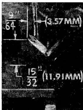
Fig. 8A
SETTING THE FEED DOGS

natural_image
Interior view of a mechanical or industrial facility with labeled components (A, B, C) and no visible text or symbols.Fig. 10
Assemble and set the differential feed dog (A, Fig. 10) and main feed dog (B) so that top surfaces of the feeding surfaces all lay in the same plane. This can be checked by sighting across feeding surface with a straight edge. Feed surfaces should now be leveled with the throat plate surface by rotating feed tilting adjusting pin (D). This pin raises or lowers the back end of both feed bars at the same time.
The feeding surfaces should be set level at the time the feeding surface first appears above the throat plate. Screw (E) locks feed tilting adjusting pin (D) in place. Now set feeding surfaces so they rise about 3/64 inch (1.19 mm) above the throat plate.
NOTE: On Styles 39500 RC-045 and RC-060, assemble and set chaining feed dog (C, Fig. 10) level with the top of throat plate when other feed dogs are at the top of their travel.
SETTING THE LOWER KNIFE
Replace lower knife holder assembly. Lower knife (A, Fig. 11) should be set with cutting edge flush with throat plate surface. Adjustments are made with hexagonal head screw (K) which holds lower knife. Lower knife is spring pressed against upper knife, so no lateral adjustment is necessary when width of trim is changed.
Lower knife may be secured in any position by tightening screw (B) and locking nut (C) against support bracket. Because screw (B) also serves as latch pin for the cloth plate latch spring, it should always be locked with nut (C) even when screw is not tightened against lower knife holder.
SETTING THE UPPER KNIFE

Fig. 11
Replace upper knife assembly. Clamp upper knife (D, Fig. 11) in position, setting nut (E) to hold clamp (F) in its most clockwise position against upper knife. At bottom of its stroke, front cutting edge of upper knife should extend not less than 1/64 inch (.40 mm) below cutting edge of lower knife. The chain guard (J) should be set down against the upper knife and slightly back from the cutting edge.

Fig. 12
After upper knife has been set for proper width of trim, screw (G) should be tightened to lock upper knife holding block (H) in place. This will simplify resetting when upper knife is replaced.
SETTING THE STITCH LENGTH
Length of stitch is determined by the combination of feed eccentricis used. Outer (left) eccentric (A, Fig. 12) actuates main (rear) feed dog; while the inner (right) eccentric (B) actuates the differential (front) feed dog.
In assembling feed eccentrics, be sure hubs are facing each other. Be careful not to damage shaft or key. Tighten nut (C) securely.
To change feed eccentrics, remove nut (C) and washer (D) from end of shaft (E). Turn handwheel in operating direction until key slot in eccentric is toward the front. Using hooked eccentric extractor (F), supplied with machine, reach behind eccentrics as shown and withdraw eccentrics. It may be necessary to move handwheel back and forth slightly during extraction.
If eccentrics are unusually tight fitting, in addition to removing nut (C) and washer (D, Fig. 13) from shaft (E), it may be helpful to remove nut (G) and feed driving connection (H). Then continue as originally suggested.

Fig. 13
SETTING THE PRESSER FOOT
Assemble the presser foot to presser arm. With needle in high position, swing presser arm into sewing position and set the presser foot to align needle holes
(front and back) and flat on throat plate. The front edge of needle hole in presser foot must be aligned with front edge of needle hole in throat plate. It is also important that the bottom of the presser foot be flat on the throat plate. If necessary, presser foot can be realigned with throat plate slots by shifting the foot lifter lever shaft (H, Fig. 14). To move the shaft, loosen collar screws (B, Fig. 14) and clamp screw (G) and then shift the foot lifter lever shaft to the left or right as required. Re-tighten collar screws and clamp screw.

Fig. 14
The foot lifter lever arm (A, Fig. 14) and the collar (B) secure the shaft. Be sure the presser arm does not bind and rise when presser foot release bushing is unlocked.
Adjust lifter lever stop screw (C) so that presser foot can be raised no higher than upper looper or upper spreader will permit; then lock the nut (D). There should be from 1/16 to 1/8 inch (1.59 to 3.17 mm) free motion of foot lifter lever before the presser foot begins to rise. This adjustment should be made with screw (E) and locked with nut (F). Re-assemble the chip guard, fabric guard and cloth plate. To assemble chip guard, turn handwheel until upper knife assembly reaches its highest position.
CLOTH PLATE REMOVAL AND ASSEMBLY
CAUTION: When removing the cloth plate (A, Fig. 15) loosen the cloth plate stud locking screw (B) and lift up cloth plate with the cloth plate stud (C) and cloth plate screw (D), assembled.
In assembly, the cloth plate screw and the cloth plate stud are tightened to the point of removing all play and yet turn in cloth plate. The cloth plate is then assembled to the machine with the flat and "V" slot of the cloth plate stud (C) towards the rear. Stud locking screw (B) is tightened securely which collapses the body of the stud to the screw (D) so that only the cloth plate will turn when opening or closing.

Fig. 15
STARTING TO OPERATE
Be sure machine is threaded according to the diagram for your style of machine (Fig. 1, 1A or 1B). With thread tensions light, set upper looper thread eyelet (N, Figs. 1 and 1A) or lower looper thread eyelet (R, Fig. 1B) about horizontal and back in its front to back location. Operate machine slowly, without presser foot in place, to make sure that chain forms and moves off the tongue freely. Swing presser foot into position, insert material and sew slowly.
NEEDLE THREAD CONTROL
While sewing on material, check needle thread control as follows:
FOR STYLE 39500 RC-045 ONLY
About 60% of needle thread is drawn from cones on needle down stroke. The remaining 40% is drawn on the upstroke. With needles at bottom of needle stroke, position needle thread eyelet (AD, Fig. 1A) so that needle thread cam pull-off (AE) just contacts needle thread.
The eyelet is adjusted correctly in its front to back position when the desired stitch is obtained with the least amount of needle thread tension when sewing over the complete speed range.
FOR STYLES 39500 RB and RC-060
Usually, all needle thread is drawn from cones on needle down stroke. At top of needle stroke, thread should be just tight enough to feed chain off stitch tongue. Needle threads tend to pull down slightly if excessive thread is pulled on the up stroke. With needles at bottom of stroke, position needle thread eyelet (AD, Fig. 1 or 1B) so that the needle thread pull-off (AE) draws the proper amount of needle thread to satisfy the above conditions.
UPPER LOOPER THREAD CONTROL (FOR STYLES 39500 RB and RC-045)
During needle down stroke, forward stroke of looper thread pull-off (AF, Fig. 1 or Fig. 1A) will draw upper looper thread through the tension. When normal amount of looper thread is drawn, upper looper thread will have almost all slack taken up as looper thread pull-off reaches its most rearward position.
FOR STYLE 39500 RC-045 ONLY
If upper looper thread has a loose appearance in the seam, move the upper looper thread eyelet (N, Fig. 1A) forward and raise slightly. If, however, the eyelet is raised too high and moved too far forward, the looper thread will tend to break excessively--even with a minimum amount of looper thread tension applied.
FOR STYLE 39500 RB ONLY
If upper looper thread has loose appearance in the seam, move the upper looper thread eyelet (N, Fig. 1) forward slightly. If, however, the eyelet is too far forward, the looper thread will tend to break excessively--even with a minimum amount of looper thread tension applied.
CAUTION! Do not try to obtain a tight looper thread appearance on the seam by carrying high tensions.
LOWER LOOPER THREAD CONTROL (FOR STYLE 39500 RC-060)
During needle down stroke, forward stroke of looper thread pull-off (AF, Fig. 1B) will draw lower looper thread through the tension. When normal amount of looper thread is drawn, lower looper thread will have almost all slack taken up as looper thread pull-off reaches its most rearward position.
If lower looper thread has a loose appearance in the seam, move lower looper thread eyelet (R, Fig. 1B) forward and raise slightly. If, however, the eyelet is raised too high and moved too far forward, the looper thread will tend to break excessively--even with a minimum amount of looper thread tension applied.
CAUTION! Do not try to obtain a tight looper thread appearance on the seam by carrying high tensions.
POSITIONING THE PURL TO OBTAIN A FLAT SEAM
If the purl is at the top edge of the garment, the seam can be opened into a near butted appearance. If, however, the purl is under the edge, a less flat and tighter seam results when opened.
FOR STYLES 39500 RC-045 and RC-060
Raising and bringing the upper looper thread eyelet (N, Fig. 1A) or the lower looper thread eyelet (R, Fig. 1B) forward causes less thread to be pulled from the cones as the looper travels to the top of its stroke and causes the purl to form more on the top of the edge. If the eyelet is raised and brought too far forward, however, the thread becomes too tight, resulting in looper thread breakage. With a reasonable amount of looper thread tension to insure a flexible chain, the looper thread eyelet should be adjusted to position the purl as desired.
FOR STYLE 39500 RB ONLY
Moving the needle thread eyelet (AD, Fig. 1) back causes less thread to be pulled from the cones as the needles travel to the top of their stroke and causes the purl to form more on the top of the edge. If the eyelet is moved back too far however, the threads become slack at the top of the stroke and the chain will not feed off the throat plate tongue. With a reasonable minimum needle thread tension to insure uniformity, the needle thread eyelet should be adjusted to position the purl as desired.
THREAD TENSIONS WITH RESPECT TO STITCH
FOR STYLES 39500 RC-045 and RC-060
The needle thread tension required is a function of needle thread and the material being sewn. In general, upper looper or lower looper thread tension should be set as high as possible without causing the needle threads to be pulled too far over the top of the seam and low enough to prevent looper thread breakage.
FOR STYLE 39500 RB ONLY
The needle threads and looper thread tensions should be set at a minimum to insure uniformity of stitch. NOTE: Tension applied to the threads at the thread stand tension disc felt (L, Fig. 1) should only be enough to prevent the threads from becoming slack between these tension pads and the tension discs mounted on the machine. All controlling tension settings to insure uniformity of stitch should be obtained by varying the tensions at the tension discs, which are mounted on the machine.
ILLUSTRATIONS AND ORDERING REPAIR PARTS
Numbers in the first column are reference numbers only, and merely indicate the position of that part in the illustration. Reference number should never be used in ordering parts. Always use the part number listed in the second column.
IDENTIFYING PARTS
Where the construction permits, each part is stamped with its part number. On some of the smaller parts, and on those where construction does not permit, an identification letter is stamped in to distinguish the part from similar ones.
PART NUMBERS REPRESENT THE SAME PART, REGARDLESS OF CATALOG IN WHICH THEY APPEAR.
TERMS
Prices are net cash and subject to change without notice. All shipments are forwarded f.o.b. shipping point. Parcel post shipments are insured unless otherwise directed. A charge is made to cover postage and insurance.

The parts illustrated on Pages 18, 20 and 22 and described on this page, page 21 and 23 represent the parts that are used on Styles 39500 RB, 39500 RC-045 and 39500 RC-060, but not used on Style 39500 QA.
Unless otherwise specified in the description, the parts are used on all the machine styles covered in this catalog. Those parts shown in phantom views and bearing no reference numbers are common to Styles 39500 QA, 39500 RB, 39500 RC-045 and 39500 RC-060.
Use Catalog No. 103 QA for all parts not illustrated or described here.
Reference numbers that are inside a bracket or box on the picture plate and have indented descriptions, indicate they are components of a complete part or assembly.
| Ref.No. | PartNo. | Description | Amt.Req. |
| 1 | 39552 AA | Needle Driving Arm, marked "L", for Styles39500 RB and RC-045 - - - - - - - - - - - - - - - - - - - - - - - - - - - - - - - - - - - - - - - - - - - - - - - - - - - - - - - - - - - - - - - - - - - - - - - - - - - - - - - - - - - - - - - - - - - - - - - - - - - - | 1 |
| - | 39552 AB | Needle Driving Arm, marked "M", for Styles39500 RC-060 only - - - - - - - - - - - - - - - - - - - - - - - - - - - - - - - - - - - - - - - - - - - - - - - - - - - - - - - - - - - - - - - - - - - - - - - - - - - - - - - - - - - - - - - - - - - - - - - - - - - | |
| 2 | 22596 E | Screw, for needle driving arm - - - - - - - - - - - - - - - - - - - - - - - - - - - - - - - - - - - - - - - - - - - - - - - - - - - - - - - - - - - - - - - - - - - - - - - - - - - - - - - - - - - - - - - - - - - - - - - - - - - | |
| 3 | 39552 AD | Stop Pin, for needle - - - - - - - - - - - - - - - - - - - - - - - - - - - - - - - - - - - - - - - - - - - - - - - - - - - - - - - - - - - - - - - - - - - - - - - - - - - - - - - - - - - - - - - - - - - - - - - - - - - 1 | |
| 4 | 154 GFS | Needle, for Styles 39500 RB and RC-045 - - - - - - - - - - - - - - - - - - - - - - - - - - - - - - - - - - - - - - - - - - - - - - - - - - - - - - - - - - - - - - - - - - - - - - - - - - - - - - - - - - - - - - - | |
| - | 154 GDS | Needle, for Style 39500 RC-060 only - - - - - - - - - - - - - - - - - - - - - - - - - - - - - - - - - - - - - - - - - - - - - - - - - - - - - - - - - - - - - - - - - - - - - - - - - - - - - - - - - - - - - - - - 1 | |
| 5 | 39563 P | Needle Thread Pull-off, for Style 39500 RB only - - - - - - - - - - - - - - - - - - - - - - - - - - - - - - - - - - - - - - - - - - - - - - - - - - - - - - - - - - - - - - - - - - - - - - - - - - - - - - - - - - - - - - - - - - - - - - - - - - 2 | |
| 6 | 39592 Z | Left Needle Thread Tension Nut, yellow - - - - - - - - - - - - - - - - - - - - - - - - - - - - - - - - - - - - - - - - - - - - - - - - - - - - - - - - - - - - - - - - - - - - - - - - - - - - - - - - - - - - - - - - - - - - - - - - - 1 | 1 |
| - | 39592 AA | Right Needle Thread Tension Nut, green - - - - - - - - - - - - - - - - - - - - - - - - - - - - - - - - - - - - - - - - - - - - - - - - - - - - - - - - - - - - - - - - - - - - - - - - - - - - - - 1 | |
| - | 39592 AB | Upper Looper Thread Tension Nut, blue,for Styles39500 RB and RC-045 - - - - - - - - - - - - - - - - - - - - - - - - - - - - - - - - - - - - - - - - - - - - - - - - - - - - - - - 1 | |
| - | 39592 AC | Lower Looper Thread Tension Nut, red, for Style39500 RC-060 - - - - - - - - - - - - - - - - - - - - - - - - - - - - - - - - - - - - - - - - - - - - - - 1 | |
| 7 | 39592 AR-1 | Needle Tension Spring - - - - - - - - - - - - - - - - - - - - - - - - - - - - - - - - - - - - - - - - 2 | |
| - | 39592 AR-1 | Looper Tension Spring, for Style 39500 RB only - - - - - - - - - - - - - - - - - - - - - - - - - 1 | |
| - | 39592 AR-2 | Looper Tension Spring, for Styles 39500 RC-045and RC-060 - - - - - - - - - - - - - - - - - - - - - - - - - - - 1 | |
| 8 | 40-46 | Washer, for No. 22806 A | 1 |
| 9 | 39592 E | Pad, for tension post mounting bracket | 1 |
| 10 | 39592 AB | Presser Foot, for Style 39500 RB only | 1 |
| - | 39592 AC | Presser Foot, for Styles 39500 RC-045 and RC-060 | 1 |
| 11 | 39530 P | Chip Guard | 1 |
| 12 | 22738 | Screw, for chip guard-- -- -- -- -- -- -- -- -- -- -- -- -- -- -- -- -- -- -- -- -- -- -- -- -- -- -- -- -- -- -- -- -- -- -- -- -- -- -- -- -- -- -- -- -- -- -- -- -- -- -- -- -- -- -- -- -- -- -- -- -- -- -- -- -- -- -- -- -- -- -- -- -- -- -- -- -- -- -- -- -- -- -- -- -- -- -- -- -- -- -- -- -- -- -- -- -- -- -- -- -- 1 | |
| 13 | 39597 AB | Stitch Tongue, marked "EK" | 1 |
| 14 | 22768 B | Screw, for stitch tongue and hinge spring | 1 |
| 15 | 39530 G | Hinge Spring | 1 |
| 16 | 22738 | Screw, for chain shield | 1 |
| 17 | 39530 S | Chain Shield, for presser foot No. 39520 AB | 1 |
| - | 39530 R | Chain Shield, for presser foot No. 39520 AC | 1 |
| 18 | 73 X | Screw, for frame thread guide, for Style39500 RC-060 only | 1 |
| 19 | 39568 R | Frame Looper Thread Eyelet, for Style39500 RC-060 only | 1 |
| 20 | 39556 J | Presser Arm | 1 |
| 21 | 39505 E | Chaining Feed Dog, 20 t.p.i., for Styles39500 RC-045 and RC-060 | 1 |
| 22 to 45 | See following page | ||

| Ref.No. | PartNo. | Description | Amt.Req. | |
| 1 to 21 | See preceding page | |||
| 22 | 39526 AC | Differential Feed Dog, 22 t.p.i., for Styles39500 RC-045 and RC-060 - - - - - - - - - - - - - - - - - - - - - - - - - - - - - - - - - - - - - - - - - - - - - - - - - - - - - - - - - - - - - - - - - - - - - - - - - - - - - - - - - - - - - - - - - - - - - - - - - - - - | 1 | |
| 23 | 22797 A | Screw, for chaining feed dog, for Styles39500 RC-045 and RC-060 - - - - - - - - - - - - - - - - - - - - - - - - - - - - - - - - - - - - - - - - - - - - - - - - - - - - - - - - - - - - - - - - - - - - - - - - - - - - - - - - - | 1 | |
| 24 | 39505 AC | Main Feed Dog, marked "AM", 22 t.p.i., forStyles 39500 RC-045 and RC-060- - - - - - - - - - - - - - - - - - - - - - - - - - - - - - - - - - - - - - - - - - - - - - - - - - - - - - - - - - - - - - - - - - - - - - - - - - - - - - - - - - - - - - - - - - - - - - - - - - - - | ||
| 25 | 39505 AB | Main Feed Dog, marked "AC", rubber coated,for Style 39500 RB only - - - - - - - - - - - - - - - - - - - - - - - - - - - - - - - - - - - - - - - - - - - - - - - - - - - - - - - - - - - - - - - - - - - - - - - - - - - - - - - - - - - - - - - - - - - - - - - - - - - | ||
| 26 | 39526 AB | Differential Feed Dog, rubber coated, for Style39500 RB only - - - - - - - - - - - - - - - - - - - - - - - - - - - - - - - - - - - - - - - - - - - - - - - - - - - - - - - - - - - - - - - - - - - - - - - - - - - - - - - - - - - - - - - - - - - - | ||
| 27 | 39525 H | Needle Guard, front, for Styles 39500 RB and RC-045 - - - - - - - - - - - - - - - - - - - - - - - - - - - - - - - - - - - - - - - - - - - - - - - - - - - - - - - - - - - - - - - - - - - - - - - - - - - - - - - - - - - - - - - - - - - - - - - - - - - | ||
| - | 39525 L | Needle Guard, front, for Style 39500 RC-060 only - - - - - - - - - - - - - - - - - - - - - - - - - - - - - - - - - - - - - - - - - - - - - - - - - - - - - - - - - - - - - - - - - - - - - - - - - - - - - - - - - - - - - - - | ||
| 28 | 39525 J | Needle Guard, rear - - - - - - - - - - - - - - - - - - - - - - - - - - - - - - - - - - - - - - - - - - - - - - - - - - - - - - - - - - - - - - - - - - - - - - - - - - - - - - - - - - | ||
| 29 | 39550 E | Lower Knife Holder Spring- - - - - - - - - - - - - - - - - - - - - - - - - - - - - - - - - - - - - - - - - - - - - - - - - - - - - - - - - - - - - - - - - - - - - - | ||
| 30 | 39524 AB-1/8 | Throat Plate, marked "AX-1/8", for Style39500 RB-1/8 only - - - - - - - - - - - - - - - - - - - - - - - - - - - - - - - - - - - - - - - - - - - - - - - - - - - | ||
| - | 39524 AB-5/32 | Throat Plate, marked "AX-5/32", for Style39500 RB-5/32 only - - - - - - - - - - - - - - - - - - - - - - - - - - - - - - - - - - - - - - - | ||
| - | 39524 AC | Throat Plate, marked "AV", for Style39500 RC-045 only - - - - - - - - - - - - - - - - - - - - - - - - - - - - | ||
| 30 A | 39528 AG | Throat Plate, marked "AY", for Style39500 RC-060 only - - - - - - - - - - - - - - - - - - - - - - - - | ||
| 31 | 39550 AF | Lower Knife Holder - - - - - - - - - - - - - - - - - - - - - - | ||
| 32 | 39550 AC | Knife Guide Plate - - - - - - - - - - - - - - - - | ||
| 33 | 39550 AE | Lower Knife Clamp Spring - - - - - - - - - - - - - - | ||
| 34 | 605 A | Screw, for lower knife clamp spring - - - - - - - - - | ||
| 35 | 22588 J | Screw, for lower knife clamp | 1 | |
| 36 | 39550 AD | Lower Knife Clamp | 1 | |
| 37 | 39540 B-20 | Main Feed Driving Eccentric | 1 | |
| 38 | 39540 B-18 | Differential Feed Driving Eccentric | 1 | |
| 39 | 39560 A | Upper Spreader, marked "E", for Style 39500 RC-060only- -- -- -- -- -- -- -- -- -- -- -- -- -- -- -- -- -- -- -- -- -- -- -- -- -- -- -- -- -- -- -- -- -- -- -- -- -- -- -- -- -- -- -- -- -- -- -- -- -- -- -- -- -- -- -- -- -- -- -- -- -- -- -- -- -- -- -- -- -- -- -- -- -- -- -- -- -- -- -- -- -- -- -- -- -- -- -- -- -- -- -- -- -- -- -- -- -- -- -- -- | ||
| 40 | 22569 D | Screw, for needle thread eyelet | 1 | |
| 41 | 39563 H | Needle Thread Eyelet, for Styles 39500 RC-045and RC-060 | 1 | |
| - | 39563 N | Needle Thread Eyelet, for Style 39500 RB only | 1 | |
| 42 | 39501 DD | Cloth Plate, for Style 39500 RB only | 1 | |
| - | 39501 D | Cloth Plate, for Style 39500 RC-045 only | 1 | |
| - | 39501 DC | Cloth Plate, for Style 39500 RC-060 only | 1 | |
| 43 | 39578 TB | Chip Guard, for Style 39500 RB only | 1 | |
| - | 39578 U | Chip Guard, for Styles 39500 RC-045 and RC-060 | 1 | |
| 44 | 39563 X | Top Cover Needle Thread Eyelet, for Styles39500 RB and RC-060 | 1 | |
| 44 A | 39563 R | Top Cover Needle Thread Eyelet, for Style39500 RC-045 only | 1 | |
| 45 | 39560 B | Lower Spreader, for Styles 39500 RB and RC-045 | 1 | |

THREAD STAND AND MISCELLANEOUS TOOLS
| Ref. No. | Part No. | Description | Amt. Req. |
| 1 | 21113 F | Thread Stand Eyelet and Support Rod, for Styles 39500 RC-045 and RC-060 | 3 |
| 2 | 21104 V | Pad, for thread cone | 3 |
| 3 | 69 S | Spool Pin | 3 |
| 4 | 21130 W-3 | Cone Support | 1 |
| 5 | 22650 CB-4 | Screw, for thread eyelet | 3 |
| 6 | 22650 CE-6 | Screw, for thread stand rod | 1 |
| 7 | 21104 AA | Thread Stand Rod | 1 |
| 8 | 652 J-24 | Washer | 1 |
| 9 | 652 J-16 | Washer | 1 |
| 10 | WA9 A | Lock Washer | 1 |
| 11 | 651 A-16 | Nut | 1 |
| 12 | SC333 A | Wood Screw, round head #9 x 5/8 inch (15.88 mm) long | 2 |
| 13 | 39592 W | Tension Post Bracket, for mounting on tableboard | 1 |
| 14 | 660-264 | "S" Hook, for treadle chain | 2 |
| 15 | 116 | Wrench, for 9/32 inch (7.14 mm) nuts | 1 |
| 16 | 39599 A | Threading Wire | 1 |
| 17 | 660-240 | Thread Tweezers | 1 |
| 18 | 21388 AU | Socket Wrench, for 3/8 inch (9.52 mm) nuts holding feed eccentricis | 1 |
| 19 | 21227 BF | Cam Extractor | 1 |
| 20 | 421 D-34 | Treadle Chain, for presser foot lifter | 1 |
| *21 | 21202 | Screwdriver, 3/16 inch (4.76 mm) diameter, 10 3/4 inches (273.05 mm) long overall (not furnished with machine) | 1 |
| † | 28604 R | Container of Oil, 16 ounces, Spec. 175 | 1 |
| † | 39595 | Isolators, rubber | 4 |
| † | 660-458 | Dust Cover | 1 |
| 22 | 21113 G | Thread Stand Eyelet and Support Rod, for Style 39500 RB only | 3 |
| 23 | 22565 C | Screw, for tension post | 1 |
| 24 | 39592 D | Tension Post, for Style 39500 RB only | 3 |
| 25 | 109 | Tension Disc, (inverted) for Style 39500 RB only | 6 |
| 26 | 39592 E | Tension Spring Pad, felt, for Style 39500 RB only | 6 |
| 27 | 51292 F-1 | Tension Spring, for Style 39500 RB only | 3 |
| 28 | 107 | Tension Post Ferrule, for Style 39500 RB only | 3 |
| 29 | 108 | Tension Post Nut, for Style 39500 RB only | 3 |
* Not furnished with machine.
† Not shown on picture plate.

natural_image
World map with latitude and longitude grid lines, showing continents and oceans (no text labels)WORLDWIDE SALES AND SERVICE
Union Special Corporation maintains sales and service facilities throughout the world. These offices will aid you in the selection of the right sewing equipment for your particular operation. Union Special Corporation representatives and service technicians are factory trained and are able to serve your needs promptly and efficiently. Whatever your location, there is a qualified representative to serve you.
Corporate
Office:
One Union Special Plaza
Huntley, IL 60142
Phone: 847·669·5101
Fax: 847•669•4454
European Distribution Center:
Union Special GmbH
Raiffeisenstrasse 3
D-71696 Möglingen, Germany
Tel: 49·07141·247·0
Fax: 49·07141·247·100
Brussels, Belgium
Charlotte, N.C.
Hong Kong, China
Huntley, IL
Leicester, England
Lille, France
Miami, FL
Milan, Italy
Möglingen, Germany
Montreal, Quebec
Osaka, Japan
Santa Fe Springs, CA
Suwanee, GA
Wayne, NJ
Other Representatives throughout all parts of the world.

Finest Quality
Union Special® INDUSTRIAL SEWING EQUIPMENT
- IDENTIFICATION OF MACHINES
- APPLICATION OF CATALOG
- STYLES OF MACHINES
- SPEED RECOMMENDATION
- OILING
- NEEDLES
- NEEDLES (Continued)
- CHANGING NEEDLES
- THREAD STAND (STYLE 39500 RB)
- THREAD STAND (STYLE 39500 RC-045)
- THREAD STAND (STYLE 39500 RC-060)
- THREADING
- TO THREAD UPPER LOOPER (STYLES 39500 RB and RC-045)
- TO THREAD LOWER LOOPER (STYLE 39500 RC-060)
- TO THREAD NEEDLES
- THREAD TENSION
- PRESSER FOOT PRESSURE
- FEED ECCENTRICS
- ASSEMBLING AND ADJUSTING SEWING PARTS
- SETTING THE NEEDLE
- SETTING THE REAR NEEDLE GUARD
- SETTING THE LOWER SPREADER AND LOWER LOOPER
- SETTING THE FRONT NEEDLE GUARD
- SETTING THE UPPER LOOPER (STYLES 39500 RB and RC-045)
- SETTING THE UPPER SPREADER (STYLE 39500 RC-060)
- SETTING THE FEED DOGS
- SETTING THE LOWER KNIFE
- SETTING THE UPPER KNIFE
- SETTING THE STITCH LENGTH
- SETTING THE PRESSER FOOT
- CLOTH PLATE REMOVAL AND ASSEMBLY
- STARTING TO OPERATE
- NEEDLE THREAD CONTROL
- FOR STYLE 39500 RC-045 ONLY
- FOR STYLES 39500 RB and RC-060
- UPPER LOOPER THREAD CONTROL (FOR STYLES 39500 RB and RC-045)
- FOR STYLE 39500 RB ONLY
- LOWER LOOPER THREAD CONTROL (FOR STYLE 39500 RC-060)
- POSITIONING THE PURL TO OBTAIN A FLAT SEAM
- FOR STYLES 39500 RC-045 and RC-060
- THREAD TENSIONS WITH RESPECT TO STITCH
- ILLUSTRATIONS AND ORDERING REPAIR PARTS
- IDENTIFYING PARTS
- TERMS
- WORLDWIDE SALES AND SERVICE
Brand : Union Special
Model : 39500RC-045
Category : Industrial sewing machine