
39500JJ - Peeler Union Special - Free user manual and instructions
Find the device manual for free 39500JJ Union Special in PDF.

| Product Type | Industrial Serging Machine (Overlock) |
| Brand | Union Special |
| Model | 39500 JJ |
| Category | Chéreuse (Serger) |
| Stitch Type | Two-thread (503-EFd-1) |
| Seam Width | 3/16 inch (standard) |
| Stitch Range | 4–8 stitches per inch |
| Maximum Speed | 7000 RPM |
| Feed Mechanism | Cam-adjusted plain feed with chaining feed dog |
| Trimming Mechanism | Upper and lower knife with spring-pressed lower knife |
| Lubrication System | Automatic, via oil reservoir |
| Oil Capacity | 6 ounces (177 ml) |
| Oil Type | Straight mineral oil, Saybolt viscosity 90–125 seconds at 100°F (38°C) |
| Needle Type | 154 GAS (curved blade, round shank, round point) |
| Needle Sizes | 022, 025, 027, 029, 032, 036, 040, 044, 049, 054 |
| Dimensions (Approx.) | 20 x 18 x 12 in (508 x 457 x 305 mm) |
| Weight (Approx.) | 40 lbs (18 kg) |
| Materials | Light to medium weight Durable Press trousers and similar garments |
| Maintenance | Daily oil level check; periodic cleaning of magnetic drain plug |
| Safety | Use genuine Union Special needles and parts; fill oil reservoir before operation |
Frequently Asked Questions - 39500JJ Union Special
User questions about 39500JJ Union Special
0 question about this device. Answer the ones you know or ask your own.
Ask a new question about this device
Download the instructions for your Peeler in PDF format for free! Find your manual 39500JJ - Union Special and take your electronic device back in hand. On this page are published all the documents necessary for the use of your device. 39500JJ by Union Special.
USER MANUAL 39500JJ Union Special
HI-STYLED HIGH SPEED TWO AND THREE NEEDLE THREAD PLAIN FEED SERGING MACHINES
Catalog No. 103 FJ
INSTRUCTIONS
FOR
ADJUSTING AND OPERATING
LIST OF PARTS
CLASS 39500
Styles
39500 FJ 39500 FL 39500 JJ
First Edition
Copyright 1967
By
Union Special Machine Co.
Rights Reserved in All Countries
UnionSpecial
MACHINE COMPANY
INDUSTRIAL SEWING MACHINES
CHICAGO
Printed in U.S.A.
November, 1971
IDENTIFICATION OF MACHINES
Each Union Special machine is identified by a Style number on a name plate on the machine. Style numbers are classified as standard and special. Standard Style numbers have one or more letters suffixed, but never contain the letter "Z". Example: "Style 39500 FJ". Special Style numbers contain the letter "Z". When only minor changes are made in a standard machine, a "Z" is suffixed to the standard Style number. Example: "Style 39500 FJZ".
Styles of machines similar in construction are grouped under a Class number which differs from the Style number in that it contains no letters. Example: "Class 39500".
APPLICATION OF CATALOG
This catalog applies specifically to the standard Styles of machines as listed herein. It can also be applied with discretion to some Special Styles of machines in Class 39500. References to directions, such as right, left, front, back, etc., are given from the operator's position while seated at the machine. Operating direction of handwheel is away from operator.
STYLES OF MACHINES
Hi-Styled High Speed Single Curved Blade Needle, One Looper, One Spreader, Two thread or Two Looper, Three Thread Serging Machines. Plain Feed, Trimming Mechanism with Spring Pressed Lower Knife, Automatic Lubricating System.
39500 FJ Light to medium duty machine for serging light, medium and heavy weight trousers and similar garments. Two thread stitch. Seam specification 503-EFd-1; standard seam width 3/16 inch; stitch range 4-8 per inch; cam adjusted feed. Maximum recommended speed 7000 R.P.M.
39500 FL Light to medium duty machine for serging light, medium and heavy weight trousers and similar garments. Three thread stitch. Seam specification 505-EFd-1; standard seam width 3/16 inch; stitch range 4-8 per inch; cam adjusted feed. Maximum recommended speed 7000 R.P.M.
39500 JJ Light to medium duty machine for serging light and medium weight trousers and similar garments of Durable Press material. Two thread stitch. Seam specification 503-EFd-1; standard seam width 3/16 inch; stitch range 4-8 per inch; cam adjusted feed. Maximum recommended speed 7000 R.P.M.
OILING
CAUTION! Oil was drained from machine when shipped, so reservoir must be filled before beginning to operate. Oil capacity of Class 39500 is six ounces. A straight mineral oil of a Saybolt viscosity of 90 to 125 seconds at 100^ Fahrenheit should be used.
Machine is filled with oil at spring cap in top cover. Oil level is checked at sight gauge on front of machine. Red tip of oil level indicator should show between gauge lines when machine is stationary.
Machine is automatically lubricated. No oiling is necessary, other than keeping main reservoir filled. Check oil daily before the morning start; add oil as required.
The drain plug screw is located at back of machine near bottom edge of base. It is a magnetic screw designed to accumulate possible foreign materials which may have entered the crank case. It should be removed and cleaned periodically.
NEEDLES
Each Union Special needle has both type and size number. The type number denotes the kind of shank, point, length, groove, finish and other details. The size number, stamped on the needle shank, denotes largest diameter of blade, measured in thousandths of an inch, midway between shank and eye. Collectively, type and size number represent the complete symbol which is given on the label of all needles packaged and sold by Union Special.
Class 39500 machines use a curved blade needle. The standard recommended needle for Styles 39500 FJ, FL and JJ is Type 154 GAS. Below is the description and sizes available of the recommended needle.
Type No.
Description and Sizes
154 GAS
Round shank, round point, curved blade, standard length, single groove, struck groove, spotted, chromium plated and is available in sizes 022, 025, 027, 029, 032, 036, 040, 044, 049, 054.
To have needle orders promptly and accurately filled, an empty package, a sample needle, or the type and size number should be forwarded. Use description on label. A complete order would read: "1000 Needles, Type 154 GAS, Size 044".
Selection of proper needle size is determined by size of thread used. Thread should pass freely through needle eye in order to produce a good stitch formation.
Success in the operation of Union Special machines can be secured only by use of needles packaged under our brand name, UnionSpecial which is backed by a reputation for producing highest quality needles in materials and workmanship for more than three-quarters of a century.
CHANGING NEEDLES
Release pressure on presser foot by turning presser foot release bushing (AG, Fig. 1 and 1A) and swing presser arm (U) out of position. Turn handwheel in operating direction until needle is at its lowest point of travel. Using hexagonal socket wrench No. 21388 AU, furnished with machine, loosen needle clamp nut about 1/4 turn. Again turn handwheel until needle is at high position; withdraw needle.
To replace needle, leave needle holder at high position and, with the flat to the left, insert needle in holder until it rests against stop pin. Keeping needle in this position, turn handwheel until holder is again at its low point of travel; then tighten nut. Return presser arm (U) to position; re-lock presser foot release bushing (AG).
THREAD STAND
After thread comes from cone on cone support (A, Fig. 1 or 1A) it is brought up through the back thread eyelet and then down through the front thread eyelet (B). Next, the upper looper thread (on Style 39500 FL only) and the needle thread on all Styles are brought through the upper hole of tension thread guide (C) from front to back and then through the lower hole, from back to front. The lower looper thread is brought through the upper hole of tension thread guide (C) from back to front, through the middle hole from front to back and then through the lower hole from back to front. All threads then continue between the tension discs (J), through tension post slot (K) in tension post (G) and on through eyelets in front thread guide (M)
NOTE: Refer to Fig. 1 for threading Styles 39500 FJ and JJ or refer to Fig. 1A for threading Style 39500 FL.


THREADING
Only parts involved in threading are shown in threading diagram (Fig. 1 and 1A). Parts are placed in their relative positions for clarity.
It will simplify the threading of these machines to follow the recommended sequence of threading the lower looper first and the needle second on Styles 39500 FJ and JJ. The recommended sequence of threading Style 39500 FL is lower looper first, upper looper second and the needle third.
Before beginning to thread, swing cloth plate open, turn handwheel in operating direction until needle (X) is at high position, release pressure on presser foot by turning presser foot release bushing (AG) and swing presser arm (U) out of position.
Be sure the threads, as they come from the tension thread guide (C), are between tension discs (J) and in tension post slots (K) in tension posts (G). The tension posts should be positioned so the tension post slot will be at the approximate angle for the different threads as indicated in Fig. 1 and 1A.
TO THREAD THE LOWER LOOPER
Double end of thread and lead it through the right eyelet of front thread guide (M, Fig. 1 or 1A). Then lead thread through both eyes of lower looper thread eyelet (R, Fig. 1 or 1A) from right to left. NOTE: thread must pass in front of looper thread pull-off (AF). Lead thread behind fabric guard (S) and through frame looper thread guide (T). Turn handwheel in operating direction until heel of lower looper (V) is all the way to the left, then thread through both eyes from left to right. Left eye of lower looper can be threaded easily if tweezers are in left hand.
TO THREAD THE UPPER LOOPER (Style 39500 FL)
Double end of thread and lead it through the left eyelet of front thread guide (M, Fig. 1A). Turn handwheel until point of upper looper (W, Fig. 1A) is all the way to the left. Lead thread through auxiliary looper thread eyelet (P) from back to front, then through both eyes of upper looper thread eyelet (N) from left to right. NOTE: thread must pass in front of looper thread pull-off (AF).
After pulling up upper looper thread tube assembly (AA), lead thread under neck of top cover casting and down through thread tube assembly (AA). Pull thread out bottom of tube; push tube down and then insert thread through the eye of upper looper from front to back.
TO THREAD THE NEEDLE
Turn handwheel in operating direction until needle (X, Fig. 1 or 1A) is at its highest position. Insert thread through the middle eyelet of front thread guide (M, Fig. 1 or 1A), then lead thread through eye of needle thread eyelet (AD) from back to front. Now lead the needle thread under the neck of top cover casting and through hole in needle thread pull-off eyelet (AB) from right to left. Thread needle from the front.
THREAD TENSION
The amount of tension on the needle and looper threads is regulated by knurled tension nuts (D, Fig. 1 or 1A). Tension on threads should be only enough to secure proper stitch formation.
PRESSER FOOT PRESSURE
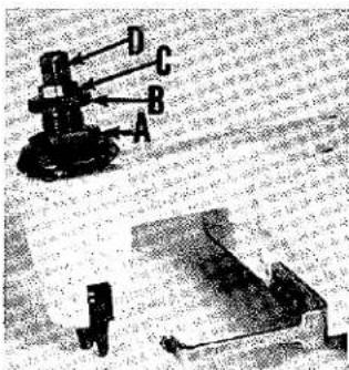
natural_image
Technical diagram of a mechanical device with labeled parts A, B, C, D (no readable text or symbols)Fig. 2
Sufficient presser foot pressure to feed work uniformly should be maintained. Should it be necessary to increase or decrease amount of pressure on presser foot, loosen lock nut (A, Fig. 2) and turn adjusting screw (B). Adjusting screw has a right hand thread, so tightening increases pressure, loosening decreases pressure. When pressure adjusting screw (B) has been properly set, tighten lock nut (A). With presser foot resting on throat plate, position locking nut (C) so that its under surface is approximately 1/32 inch to 1/16 inch from the top surface of adjusting screw (B). Set cap (D) against locking nut (C).
FEED ECCENTRICS
Feed eccentricis used in these machines have been selected to produce approximately 5 stitches per inch. It will be noted that the part number of the feed eccentric is No. 39540 B-5. Minor numbers of the part symbol indicates approximately the number of stitches produced when using that eccentric. Unless otherwise specified, machine will be shipped with above eccentric.
The following stitch number feed eccentrics are available under No. 39540 B=4, -5, -6, -7, -8, -9, -10, -11, -12, -13, -14, -15, -16, -18, -20, -22, -24, -26, -28, -30, -32, -34, -36, -40. Only one eccentric is supplied with each machine. Additional eccentrics may be ordered separately. To order an eccentric, use No. 39540 B with a minor number suffixed to indicate approximately the number of stitches desired. Example: "39540 B-5".
ASSEMBLING AND ADJUSTING SEWING PARTS
Before assembling and adjusting sewing parts, remove cloth plate, fabric guard, chip guard, upper knife assembly and lower knife holder assembly; then follow this suggested sequence.
NOTE: Adjusting instructions will pertain to all styles of machines covered in this catalog, unless otherwise specified.
SETTING THE NEEDLE
With throat plate assembled in position, needle should center in the front end of needle slot. When needle is at high position, needle point should be set 33/64 inch above the throat plate (Fig. 3). To align needle or set the height above the throat plate, move needle driving arm (A, Fig. 3) by loosening clamp screw (B). After needle has been properly set, tighten clamp screw and remove throat plate.

Fig. 4
At this point, insert lower looper (A, Fig. 4) into bar (B). With lower looper at the left end of its stroke, set looper point 1/8 inch from center of needle (Fig. 4), using looper gauge No. 21225-1/8. Do not have lower looper deflecting needle. Tighten nut (C).
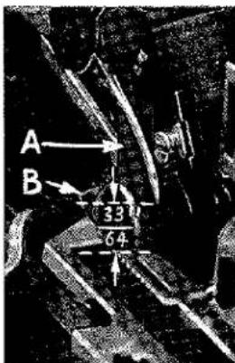
Fig. 3
Now assemble the main feed dog (E, Fig. 5).
SETTING THE REAR NEEDLE GUARD
Set rear needle guard (A, Fig. 5) as high as possible, without interfering with either lower looper or movement of lower knife holder, but still in position to deflect needle forward .002-.004 inch. Screw (B) is used to set rear needle guard. Make sure there is no interference between rear needle guard and lower looper.
SETTING THE LOWER LOOPER
Now finish lower looper adjustment. As lower looper moves to the right, its point should be set into the needle scarf (A, Fig. 6) until the needle springs forward from rear needle guard surface another .002-.004 inch.
SETTING THE FRONT NEEDLE GUARD
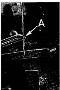
natural_image
Black-and-white photo of a mechanical or structural component with an arrow labeled 'A' pointing to a vertical line (no readable text or symbols)Fig. 6
Assemble front needle guard (C, Fig. 5). When lower looper is springing needle off back guard, set front needle guard as close as possible to needle without touching. Screw (D) is used to adjust and set front needle guard. After this setting make sure there is no interference between needle guards and main feed dog.
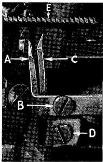
Fig. 5
SETTING THE SPREADER (Styles 39500 FJ and JJ)
Insert spreader (A, Fig. 7) in its holder. Screw (B) holds spreader in its holder, and permits it to be pushed in or out or turned around its shank. Insert spreader holder into spreader shaft, if it is not already in place. Screw (C, Fig. 7) on clamp collar holds spreader holder in the shaft, and allows holder to be rotated or adjusted laterally.
Preliminary Setting: When spreader is at the right end of its stroke, spreader holder should be set to position spreader shank about vertical (Fig. 7). Top end of spreader shank should extend 1/32 to 1/16 inch above the spreader holder (Fig. 7).

Fig. 7

Fig. 8
As spreader moves from right to left, the Vee notch of the spreader should pass just behind the eye of the lower looper, with .002 to .004 inch clearance between spreader and lower looper (Fig. 8).
Turn the handwheel until spreader is at the left end of its travel. At this position, the lower point of the spreader should extend about 5/32 inch to the left of the centerline of the needle and should be 31/64 inch above the top of the throat plate (Fig. 9). If resetting is necessary, do it by moving the spreader holder (A, Fig. 9).
SETTING THE SPREADER (Styles 39500 FJ and JJ) (Continued)
Now check setting between spreader and needle. If needle rubs the back of spreader, pull spreader out of its holder slightly and rotate spreader holder forward a short distance. These same adjustments, in opposite movement, will reduce the clearance between spreader and needle. Reset to lower looper (Fig. 8).
SETTING THE UPPER LOOPER (Style 39500 FL)

Fig. 9
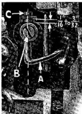
Fig. 7A
Insert upper looper (A, Fig. 7A) in its holder. Screw (B) holds upper looper in its holder, and permits it to be pushed in or out or turned around its shank. Insert upper looper holder into upper looper shaft, if it is not already in place. Screw (C, Fig. 7A) on clamp collar holds upper looper in the shaft, and allows holder to be rotated or adjusted laterally. When upper looper is at the right end of its stroke, upper looper holder should be set to position upper looper shank back of vertical (Fig. 7A). Top end of upper looper shank should extend 1/16 to 3/32 inch above the upper looper holder (Fig. 7A). Be sure there is clearance between heel of looper and casting.
As upper looper moves from right to left, the upper looper point should be set to cross the lower looper to the left of the lower looper eye with .002 to .004 inch clearance (Fig. 8A).

Fig. 8A
Turn the handwheel until upper looper is at the left end of its travel. At this position, the point of the upper looper should extend about 5/32 inch to the left of the centerline of the needle and should be 1/2 inch above the top of the throat plate (Fig. 9A). If resetting is necessary, do it by moving the upper looper holder (A, Fig. 9A).
The 1/2 inch dimension is increased by turning the upper looper holder in a counterclockwise direction, looking from the left end of machine. The 5/32 inch dimension is increased by pulling the upper
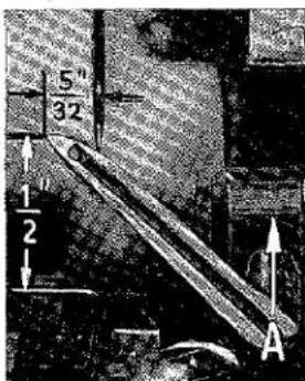
Fig. 9A
looper holder to the left, out of the upper looper shaft. After these changes are made, it may be necessary to turn upper looper around its shank slightly to maintain the condition shown in Fig. 8A.
Now check setting between upper looper and needle. If needle rubs the back of upper looper, pull looper out of its holder slightly and rotate looper a short distance counterclockwise looking from left end of machine. Reset to maintain dimensions of Figs. 7A, 8A and 9A.
SETTING THE FEED DOGS
Assemble chaining feed dog (B, Fig. 10) to main feed dog (A).

Fig. 10
Feed dogs should be leveled with throat plate surface by rotating feed tilting adjusting pin (A, Fig. 11). This pin raises or lowers the back end of feed bar. Feed dogs should be set level at the time teeth first appear above throat plate. Screw (B) locks feed tilting adjusting pin in place. Now set feed dogs at highest point of travel: main feed dog teeth should be set 3/64 inch above throat plate and chaining feed dog teeth should be set about flush with surface of throat plate.
SETTING THE LOWER KNIFE
Replace lower knife holder assembly. Lower knife (A, Fig. 12) should be set with cutting edge flush with throat plate surface. Adjustments are made with hexagonal head screw which holds lower knife. Lower knife is spring pressed against upper knife, so no lateral adjustment is necessary when width of trim is changed.
Lower knife may be secured in any position by tightening screw (B) and locking nut (C) against support bracket. Because screw (B) also serves as latch pin for the cloth plate latch spring, it should always be locked with nut (C) even when screw is not tightened against lower knife holder.
SETTING THE UPPER KNIFE
Replace upper knife assembly. Clamp upper knife (D, Fig. 12) in position, setting nut (E) to hold clamp (F) in its most clockwise position against upper knife. At the bottom of its stroke, front cutting edge of upper knife should extend not less than 1/64 inch below cutting edge of lower knife. The chain guard (not shown in Fig. 12) should be set down against the upper knife and slightly back from the cutting edge.

Fig. 11
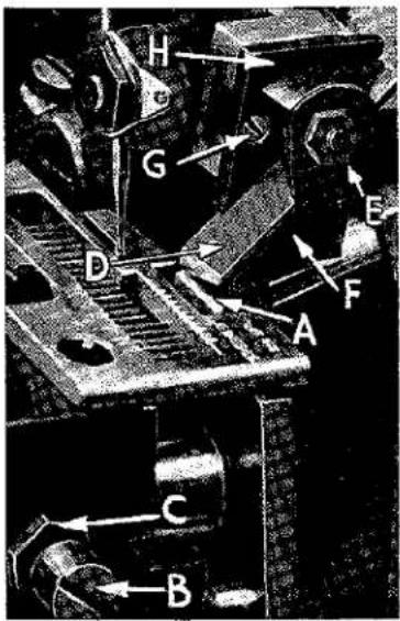
Fig. 12
After upper knife has been set for proper width of trim, screw (G) should be tightened to lock upper knife holding block (H) in place. This will simplify resetting when upper knife is replaced.
SETTING THE STITCH LENGTH
Length of stitch is determined by feed eccentric used. Note that the part number of the feed eccentric used in these machines is No. 39540 B-5.
SETTING THE STITCH LENGTH (Continued)
In assembling the feed eccentric (A, Fig. 13), be sure the hub and oil groove is to the left. Beveled edge of feed eccentric spacer (B) should also be to the left side, so the undercut on the spacer will be over the hub on the feed eccentric. Be careful not to damage shaft or key. Assemble washer (D) and tighten nut (C) securely.
To change feed eccentrics, remove nut (C), washer (D) and feed eccentric spacer (B). Turn handwheel in operating direction until key slot in eccentric is toward the front. Using hooked eccentric extractor (E), supplied with machine, reach behind eccentric as shown and withdraw eccentric. It may be necessary to move handwheel back and forth slightly during extraction.
SETTING THE PRESSER FOOT
Assemble the presser foot to presser arm. With needle in high position, swing presser arm into sewing position and set the presser foot to align needle holes (front and back) and flat on throat plate. The front edge of needle hole in presser foot must be aligned with front edge of needle hole in throat plate. It is also important that the bottom of the presser foot be flat on the throat plate. If necessary, presser foot can be realigned with throat plate slots by shifting the foot lifter lever shaft (H, Fig. 14). To move the shaft, loosen collar screws (B, Fig. 14) and clamp screw (G) and then shift the foot lifter lever shaft to the left or right as required. Retighten collar screws and clamp screw.
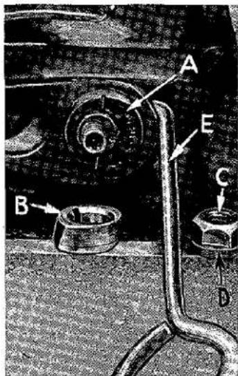
Fig. 13

Fig. 14
The foot lifter lever arm (A, Fig. 14) and the collar (B) secure the shaft. Be sure the presser arm does not bind and rise when presser foot release bushing is unlocked.
Adjust lifter lever stop screw (C) so that presser foot can be raised no higher than upper looper or spreader will permit: then lock the nut (D). There should be from 1/16 to 1/8 inch free motion of foot lifter lever before the presser foot begins to rise. This adjustment should be made with screw (E) and locked with nut (F). Re-assemble the chip guard, fabric guard and cloth plate. To assemble chip guard, turn handwheel until upper knife assembly reaches its
highest position.
STARTING TO OPERATE
Be sure machine Styles 39500 FJ and JJ are threaded according to threading diagram Fig. 1 and that machine Style 39500 FL is threaded according to threading diagram Fig. 1A.
With thread tensions light, set looper thread eyelet (R, Fig. 1) or looper thread eyelets (N and R, Fig. 1A) about horizontal and in the middle of their front to back location. Operate machine slowly, without presser foot in place, to make sure chain forms and moves off the tongue freely.
Swing presser foot into position, insert material and sew slowly.
NEEDLE THREAD CONTROL (Styles 39500 FJ, JJ - 503 Stitch)
While sewing on material, check needle thread control as follows: About 75% of needle thread required for the stitch should be drawn on needle downstroke. To increase thread drawn on downstroke, position needle thread eyelet (AD) farther to the rear.
LOWER LOOPER THREAD CONTROL (Styles 39500 FJ, JJ - 503 Stitch)
With material under presser foot, set lower looper thread eyelet (R, Fig. 1) back and down far enough so thread is a little slack when spreader reaches its extreme left position. Looper thread eyelet (R) should be about horizontal.
Frame looper thread guide (T) should be set with its left hand eyelet approximately 1/8 inch right of looper (V) heel eyelet at the time lower looper is at extreme left end of its travel.
THREAD TENSIONS
Before proceeding, balance both tensions to give a normal appearing stitch. Moderate change in these tensions will not markedly effect the purl.
SPECIAL ADJUSTMENTS
SKIPPING: For occasional skipping, check and/or adjust as outlined below:
- Recheck lower looper - needle setting. See "Setting the Needle", page 8.
- Recheck spreader - lower looper crossing. See "Setting the Spreader", page 9.
- Check clearance between needle and spreader. See that spreader moves far enough left past needle.
Setting 1 and 2 should be made quite carefully. If it can be determined by appearance that skip is definitely not a needle loop skip, reposition looper thread eyelet (R) by lowering it slightly and bringing eyelet holes in close to bend in looper thread pull-off (AF). After this change, increase looper thread tension as much as possible without distorting stitch.
CAUTION: Looper thread must, as before, be slightly slack as spreader reaches its extreme left position, or stitch will appear tight on top side.
NEEDLE THREAD CONTROL (Style 39500 FL - 505 Stitch)
While sewing on material, check needle thread control as follows: About 60% of needle thread required for the stitch should be drawn on needle downstroke.
To increase thread drawn on downstroke, position needle thread eyelet (AD, Fig. 1A) farther to the rear.
LOWER LOOPER THREAD CONTROL (Style 39500 FL - 505 Stitch)
Set lower looper thread eyelet (R, Fig. 1A) about horizontal and all the way forward in its slot.
Frame looper thread guide (T) should be set with its left hand eyelet approximately 1/8 inch right of lower looper heel eyelet, when lower looper is at the left end of its stroke.
UPPER LOOPER THREAD CONTROL (Style 39500 FL - 505 Stitch)
With material under presser foot, set upper looper thread eyelet (N, Fig. 1A) to rest on top of lower looper thread eyelet (R), and back far enough so upper looper thread is a little slack when upper looper reaches the left end of its stroke.
POSITIONING THE SQUARE EDGE (Style 39500 FL - 505 Stitch)
Position of lower looper thread at the edge is located by balancing needle and upper looper thread tensions.
To reduce amount of lower looper thread in the stitch, or close the edge more, increase lower looper thread tension.

Fig. 15
TO REMOVE CRANKSHAFT
Crankshaft can be withdrawn easier if these steps are followed:
- Drain oil by removing plug screw located on back of machine near bottom edge of base.
- Remove top and bottom covers of machine.
- Remove feed eccentric nut (A, Fig.15) and washer (B), and, with the aid of the eccentric extractor, slip off the eccentrics (C).
- Remove key (D).
- Remove three counterweights (E). Identify these counterweights so that they will be re-assembled in the proper places.
- Remove screw (F) which holds crankshaft split bearing. This screw is reached through bottom of bed casting.
TO REMOVE CRANKSHAFT (Continued)
-
Remove caps of bearings on crankshaft at points G, H, and J. When re-assembling bearing caps make sure they are in their original position. Trade marks are stamped on both halves of the caps and both trade marks should be on the same side of the bearings. Also, screws should be re-assembled in the same holes from which they were removed.
-
Loosen clamp nut (A, Fig. 16) which holds upper knife driving arm (B). Access to clamp nut is through top cover. Draw driving arm to the left until upper knife driving lever (C) and connecting rod (D) drop, allowing removal of bearing cap (E). This is at bearing point (K, Fig. 15) on crankshaft. Observe same precautions when re-assembling cap as described in 7 above.
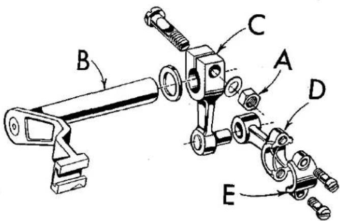
Fig. 16
-
Remove screw (L, Fig. 15) which holds inner right crankshaft bearing. This screw is reached through bottom of bed casting.
-
Loosen two screws (M) in fan collar; remove both halves of cooling fan.
-
Remove screw (N); take off pulley cap (P).
-
Loosen two screws (R); remove pulley (S).
-
Remove three screws (T); take off bearing retaining plate (U); also, spacer collars (V) and (W) may be removed at this time.
-
Crankshaft may now be removed.
-
If necessary to replace ball bearing (X), it should be pressed off shaft on an arbor press. In replacing bearing it must be pressed on carefully until it seats against ground thrust washer (Y).
-
Carefully observing reverse of the foregoing operations should simplify re-assembly of crankshaft. Checking exploded view drawings for location of various parts and constant testing for binds during re-assembly will also prove helpful.
-
Before re-assembling, thoroughly clean and dry top and bottom covers and gaskets. Before re-assembling bottom cover make sure that spring pressed oil wick which lubricates left crankshaft bearing is inserted in hole in casting and that it contacts shaft. The wick stands vertically on its spring against bottom cover. Coat oil drain plug with a sealing compound before re-assembling to prevent oil leakage. No. 1 Crane Lead Seal is recommended.
ORDERING REPAIR PARTS
ILLUSTRATIONS
This catalog has been arranged to simplify ordering repair parts. Exploded views of various sections of the mechanism are shown so that the parts may be seen in their actual position in the machine. On the page opposite the illustration will be found a listing of the parts with their part numbers, description and the number of pieces required in the particular view being shown.
Numbers in the first column are reference numbers only, and merely indicate the position of that part in the illustration. Reference number should never be used in ordering parts. Always use the part number listed in the second column.
Component parts of sub-assemblies which can be furnished for repairs are indicated by indenting their descriptions under the description of the main sub-assembly. Example:
| 42 | 29126 DF | Lower Looper Drive Lever Connecting Rod Assembly--- | 1 |
| 43 | 39544 U | Lower Looper Bar Driving Lever---- | 1 |
| 44 | 666-255 | Felt, for connecting rod---- | 1 |
| 45 | 22729 D | Screw, for connecting rod---- | 2 |
| 46 | 97 | Screw, for ball joint guide fork---- | 2 |
| 47 | 39544 S | Ball Joint Guide Fork---- | 1 |
| 48 | 22729 E | Screw, for connecting rod---- | 2 |
It will be noted in the above example that the eccentric, ball stud, and bearing are not listed. The reason is that replacement of these parts individually is not recommended, so complete sub-assembly should be ordered.
Where the parts for all the styles covered in this catalog are not the same, the difference will be shown in the illustrations or mentioned in the descriptions. When a part is used in all machines covered by this catalog no machine style will be mentioned.
At the back of the book will be found a numerical index of all the parts shown in this book. This will facilitate locating the illustration and description when only the part number is known.
IDENTIFYING PARTS
Where the construction permits, each part is stamped with its part number. On some of the smaller parts, and on those where construction does not permit, an identification letter is stamped in to distinguish the part from similar ones.
PART NUMBERS REPRESENT THE SAME PART, REGARDLESS OF CATALOG IN WHICH THEY APPEAR.
USE GENUINE NEEDLES AND REPAIR PARTS
Success in the operation of these machines can be secured only with genuine Union Special Needles and Repair Parts as furnished by the Union Special Machine Company, its subsidiaries and authorized distributors. They are designed according to the most scientific principles and are made with utmost precision. Maximum efficiency and durability are assured.
Genuine needles are packaged with labels marked Union Special. Genuine repair parts are stamped with the Union Special trade mark. Each trade mark is your guarantee of the highest quality in materials and workmanship.
TERMS
Prices are net cash and subject to change without notice. All shipments are forwarded f.o.b. shipping point. Parcel post shipments are insured unless otherwise directed. A charge is made to cover postage and insurance.
TORQUE REQUIREMENTS
Torque (measured in inch-pounds) is a rotating force (in pounds) applied through a distance by a lever (in inches or feet). This is accomplished by a wrench, screw driver, etc. Many of these devices are available, which when set at the proper amount of torque will tighten the part to the correct amount and no tighter.
All straps and eccentrics should be tightened to 19-21 inch-pounds, unless otherwise noted. All other nuts, bolts, screws, etc., should be tightened by hand as tightly as possible, unless otherwise noted.
The screws requiring a specific torque will be indicated on the picture plates.
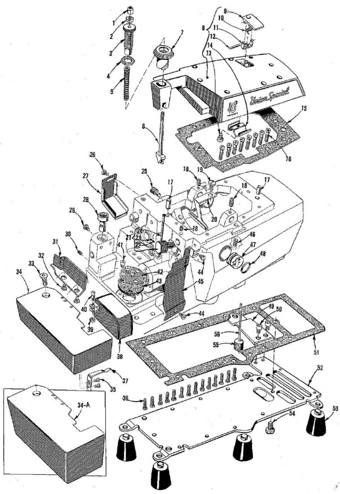
MAIN FRAME, MISCELLANEOUS COVERS AND PLATES
| Ref.No. | PartNo. | Description | Amt.Req. |
| 1 | 39557 B | Presser Spring Plunger Cap Nut | 1 |
| 2 | 39557 E | Presser Spring Plunger Locking Nut | 1 |
| 3 | 39557 C | Presser Spring Plunger Adjusting Screw | 1 |
| 4 | 39557 F | Lock Nut, for adjusting screw | 1 |
| 5 | 39557 | Presser Spring | 1 |
| 6 | 39557 A | Presser Spring Plunger | 1 |
| 7 | 39556 A | Presser Foot Release Bushing | 1 |
| 8 | 39582 AD | Top Cover | 1 |
| 9 | 39582 AF | Oil Filler Cup | 1 |
| 10 | 39582 V | Spring | 1 |
| 11 | 39582 AG | Hinge Bracket | 1 |
| 12 | 51-103 Blk | Hinge Pin | 1 |
| 13 | 22562 A | Screw, for hinge bracket | 1 |
| 14 | 39582 W | Oil Guard | 1 |
| 15 | 39582 AE | Top Cover Gasket | 1 |
| 16 | 22541 | Screw, for top cover | 8 |
| 17 | 667 D-8 | Dowel Pin | 2 |
| 18 | 22565 | Screw, for thread tube and upper looper rocker shaft | 3 |
| 19 | 22569 D | Screw, for oil collector plate | 1 |
| 20 | 39594 R | Oil Collector Plate | 1 |
| 21 | 29477 GW | Upper Looper Thread Tube Assembly | 1 |
| 22 | 39568 J | Thread Tube Tension Spring | 1 |
| 23 | 22743 | Screw, for thread tube tension spring | 1 |
| 24 | 39568 G | Thread Tube | 1 |
| 25 | 22571 E | Magnetic Oil Drain Plug Screw | 1 |
| 26 | 90 | Screw, for feed bar oil shield | 1 |
| 27 | 39534 R | Feed Bar Oil Shield | 1 |
| 28 | 39501 K | Cloth Plate Stud | 1 |
| 29 | 22569 | Screw, for cloth plate stud | 1 |
| 30 | 22565 F | Screw, for feed adjusting pin | 1 |
| 31 | 39578 F | Cloth Plate Fabric Guard | 1 |
| 32 | 138 | Screw, for cloth plate fabric guard | 2 |
| 33 | 22657 D-12 | Screw, for cloth plate | 1 |
| 34 | 39501 DG | Cloth Plate, for semi and fully-submergedinstallation | 1 |
| 34A | 39501 EE | Cloth Plate, for non-submerged installation | 1 |
| 35 | 90 | Screw, for latch spring | 2 |
| 36 | 22569 | Screw, for bottom cover | 14 |
| 37 | 39532 A | Cloth Plate Latch Spring | 1 |
| 38 | 39582 K | Feed Mechanism cover | 1 |
| 39 | 41071 G | Nut, for feed mechanism cover | 1 |
| 40 | 86 X | Screw, for feed mechanism cover | 1 |
| 41 | 22569 A | Screw, for oil filter screen and strainer | 3 |
| 42 | 39594 G | Oil Filter Screen | 1 |
| 43 | 39594 H | Oil Strainer | 1 |
| 44 | 22569 D | Screw, for chip guard | 2 |
| 45 | 39578 U | Chip Guard | 1 |
| 46 | 22894 AD | Screw, for lower looper bar driving lever shaft | 1 |
| 47 | 39593 H | Oil Sight Gauge | 1 |
| 48 | 660-243 | Oil Gauge Seal Ring | 1 |
| 49 | 39582 F | Bottom Cover Extension | 1 |
| 50 | 22653 D-4 | Screw, for bottom cover extension | 2 |
| 51 | 39582 Y | Bottom Cover Gasket | 1 |
| 52 | 39582 X | Bottom Cover | 1 |
| 53 | 39595 | Isolators | 4 |
| 54 | 22586 R | Screw, for bottom cover | 1 |
| 55 | 39593 C | Oil Gauge Float | 1 |
| 56 | 39593 D | Oil Gauge Indicator | 1 |
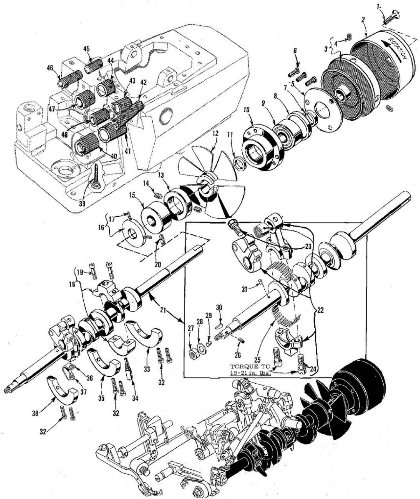
CRANKSHAFT MECHANISM AND BUSHINGS
| Ref.No. | PartNo. | Description | Amt.Req. |
| 1 | 22769 B | Screw, pulley cap | 1 |
| 2 | 39521 D | Pulley Cap | 1 |
| 3 | 39521 C | Pulley | 1 |
| 4 | 95 | Screw, for pulley | 2 |
| 5 | 39590 H | Crankshaft Ball Bearing Retaining Plate | 1 |
| 6 | 22541 A | Screw, for crankshaft ball bearing retaining plate | 3 |
| 7 | 39590 S | Spacer Collar | 1 |
| 8 | 39590 R | Ball Bearing Stop Collar | 1 |
| 9 | 660-268 | Crankshaft Ball Bearing | 1 |
| 10 | 39590 G | Crankshaft Ball Bearing Housing | 1 |
| 11 | 39590 J | Thrust Washer | 1 |
| 12 | 39591 G | Crank Chamber Cooling Fan | 1 |
| 13 | 39591 H | Crank Chamber Cooling Fan Collar | 1 |
| 14 | 22894 D | Screw, for crank chamber cooling fan collar | 2 |
| 15 | 39590 K | Crankshaft Bearing, inner right | 1 |
| 16 | 39590 P | Oil Slinger Collar | 1 |
| 17 | 77 Q | Screw, for oil slinger collar | 2 |
| 18 | 39590 D | Crankshaft Split Bearing | 1 |
| 19 | 97 A | Screw, for crankshaft split bearing | 2 |
| 20 | 22565 F | Screw, for inner right crankshaft bearing | 1 |
| 21 | 29477 JM | Crankshaft and Needle Driving Arm Crank Assembly | 1 |
| 22 | 29477 JN | Needle Driving Arm Crank and Connecting Rod Assembly | 1 |
| 23 | 22596 G | Screw, for needle driving arm crank | 1 |
| 24 | 22587 M | Screw, for needle driving arm connecting rod | 2 |
| 25 | 39516-625 | Needle Bearing, .0625 inch diameter | 28 |
| 39516-626 | Needle Bearing, .0626 inch diameter | 28 | |
| 39516-627 | Needle Bearing, .0627 inch diameter | 28 | |
| 26 | 30-92 Blk | Wood Plug | 1 |
| 27 | 258 | Nut | 1 |
| 28 | 40-46 | Washer | 1 |
| 29 | CO67 E | Cork Plug | 1 |
| 30 | 39541 A | Feed Driving Eccentric Key | 1 |
| 31 | 51-228 Blk | Vent Plug | 1 |
| 32 | 22747 B | Screw, for crankshaft counterweight | 6 |
| 33 | 39591 B | Crankshaft Counterweight, right | 1 |
| 34 | 39590 N | Stud, for crankshaft split bearing | 1 |
| 35 | 39591 A | Crankshaft Counterweight, middle | 1 |
| 36 | 39594 N | Oil Splasher | 1 |
| 37 | 28 | Screw, for oil splasher | 1 |
| 38 | 39591 K | Crankshaft Counterweight, left | 1 |
| 39 | 666-94 | Oil Wick and Spring | 1 |
| 40 | 39590 | Crankshaft Bushing, left | 1 |
| 41 | 39590 T | Crankshaft Bushing, inner left | 1 |
| 42 | 39544 L | Lower Looper Bar Bushing | 1 |
| 43 | 39552 P | Needle Driving Arm Crank Bushing, right | 1 |
| 44 | 39573 L | Upper Knife Driving Arm Bushing, right | 1 |
| 45 | 39142 G | Foot Lifter Shaft Bushing, right | 1 |
| 46 | 39555 E | Foot Lifter Shaft Bushing, left | 1 |
| 47 | 39573 K | Upper Knife Driving Arm Bushing, left | 1 |
| 48 | 39552 N | Needle Driving Arm Crank Bushing, left | 1 |


NEEDLE DRIVE AND FEED MECHANISM
| Ref. No. | Part No. | Description | Amt. Req. |
| 1 | 39536 E | Nut, for feed bar driving stud | 1 |
| 2 | 39535 C | Feed Adjusting Pin | 1 |
| 3 | 22565 F | Screw, for feed adjusting pin | 1 |
| 4 | 39578 P | Fabric Guard Mounting Bracket | 1 |
| 5 | 8372 A | Washer, for fabric guard mounting bracket | 2 |
| 6 | 22569 B | Screw, for fabric guard mounting bracket | 2 |
| 7 | 87 | Screw, for fabric guard | 2 |
| 8 | 39578 M | Fabric Guard | 1 |
| 9 | 22569 | Screw, for feed bar guide, left | 2 |
| 10 | 8372 A | Washer, for feed bar guide, left | 2 |
| 11 | 39535 F | Feed Bar Guide, left | 1 |
| 12 | 39535 J | Feed Bar Guide Block | 1 |
| 13 | 39534 G | Main Feed Bar | 1 |
| 14 | 39535 D | Feed Bar Guide, right | 1 |
| 15 | 22569 B | Screw, for feed bar guide, right | 2 |
| 16 | 53634 C | Washer, for feed bar guide, right | 2 |
| 17 | 39536 B | Feed Bar Driving Stud | 1 |
| 18 | 39503 A | Edge Guide, adjustable | 1 |
| 19 | 604 | Screw, for adjustable edge guide | 2 |
| 20 | 39503 D | Edge Guide Swinging Arm | 1 |
| 21 | 12957 E | Spring Washer, for swinging arm | 1 |
| 22 | 22758 E | Screw, for swinging arm | 1 |
| 23 | 22569 C | Screw, for edge guide mounting bracket | 2 |
| 24 | 39503 C | Edge Guide Mounting Bracket | 1 |
| 25 | 39534 H | Feed Bar Thrust Washer | 1 |
| 26 | 22569 G | Screw, for feed bar thrust washer | 3 |
| 27 | 39538 | Feed Lift Block | 1 |
| 28 | 39536 D | Feed Bar Spacer | 1 |
| 29 | 39505 K | Chaining Feed Dog, marked "K", 16 teeth per inch, for Styles 39500 FJ, FL | 1 |
| 39505 AK | Chaining Feed Dog, marked "CF", 22 teeth per inch, for Style 39500 JJ | 1 | |
| 30 | 39505 J | Main Feed Dog, 16 teeth per inch, for Styles 39500 FJ, FL | 1 |
| 39505 AJ | Main Feed Dog, 22 teeth per inch, for Style 39500 JJ | 1 | |
| 31 | 22528 | Screw, for main feed dog | 1 |
| 32 | 22768 B | Screw, for chaining feed dog | 1 |
| 33 | 39536 C | Feed Bar Driving Connection Bushing | 1 |
| 34 | 39536 AE | Main Feed Bar Driving Connection | 1 |
| 35 | 39540 B-5 | Main Feed Driving Eccentric | 1 |
| 36 | 39540 K | Feed, Eccentric Spacer | 1 |
| 37 | 40-46 | Washer | 1 |
| 38 | 258 | Nut | 1 |
| 39 | 14077 | Nut, for needle clamp stud | 1 |
| 40 | 39563 Z | Needle Thread Pull-off Eyelet | 1 |
| 41 | 154 GAS | Needle | 1 |
| 42 | 39552 | Needle Driving Arm | 1 |
| 43 | 50-774Blk | Stop Pin, for needle driving arm | 1 |
| 44 | 22596 E | Screw, for needle driving arm | 1 |
| 45 | 39551 F | Needle Clamp Stud | 1 |
| 46 | 39568 A | Looper Thread Pull-off | 1 |
| 47 | 39568 Y | Looper Thread Pull-off Lever | 1 |
| 48 | 88 B | Screw, for looper thread pull-off lever | 2 |
| 49 | 660-207 | Oil Seal Ring, for needle driving shaft | 1 |
| 50 | 39552 C | Thrust Washer, for needle driving arm crank | 2 |
| 51 | 28 | Screw, for oil splasher | 1 |
| 52 | 39594 N | Oil Splasher | 1 |
| 53 | 39552 R | Needle Driving Shaft | 1 |
| 54 | 22513 | Screw, for looper thread pull-off | 1 |

SPREADER/UPPER LOOPER AND LOWER LOOPER DRIVING PARTS
| Ref.No. | PartNo. | Description | Amt.Req. |
| 1 | 39508 A | Upper Looper, marked "CC", for Style 39500 FL | 1 |
| 1A | 39560 A | Spreader, for Styles 39500 FJ, JJ | 1 |
| 2 | 39543 | Spreader/Upper Looper Holder | 1 |
| 3 | 22564 G | Screw, for spreader/upper looper holder | 1 |
| 4 | 39543 A | Spreader/Upper Looper Holder Collar | 1 |
| 5 | 22 KII | Screw, for spreader/upper looper holder collar | 1 |
| 6 | 22503 F | Screw, for cam follower locking clamp | 1 |
| 7 | 39543 E | Cam Follower Locking Clamp | 1 |
| 8 | 1025 L | Lock Screw, for bushing and cam guide screw | 1 |
| 9 | 22565 H | Screw, for bushing and cam guide | 1 |
| 10 | 39543 T | Cam Follower | 1 |
| 11 | 39543 S | Bushing and Cam Guide | 1 |
| 12 | 39543 K | Spreader/Upper Looper Drive Shaft | 1 |
| 13 | 97 | Screw, for ball joint guide fork | 2 |
| 14 | 39544 J | Ball Joint Guide Fork, for upper looper drive assembly | 1 |
| 15 | 39543 V | Upper Looper Drive Ball Stud | 1 |
| 16 | 482 C | Spreader/Upper Looper Drive Shaft Collar | 1 |
| 17 | 22894 C | Screw, for spreader/upper looper drive shaft collar | 2 |
| 18 | 22565 | Screw, for spreader/upper looper drive shaft | 2 |
| 19 | 7446 A | Spreader/Upper Looper Drive Shaft | 1 |
| 20 | 1280 | Nut, for locking stud | 1 |
| 21 | 39543 R | Washer, for locking stud | 1 |
| 22 | 43143 N | Locking Stud, for spreader/upper looper drive lever | 1 |
| 23 | 39543 H | Spreader/Upper Looper Drive Lever | 1 |
| 24 | 39543 M | Clamp Collar, for spreader/upper looper drive shaft | 1 |
| 25 | 22562 A | Screw, for clamp collar | 1 |
| 26 | 39543 P | Spreader/Upper Looper Shaft Thrust Washer | 2 |
| 27 | 39543 U | Spreader/Upper Looper Connecting Rod | 1 |
| 28 | 22729 D | Screw, for spreader/upper looper connecting rod | 4 |
| 29 | 28 | Screw, for oil splasher | 1 |
| 30 | 39594 N | Oil Splasher | 1 |
| 31 | 77 | Screw, for lower looper bar connecting link pin | 2 |
| 32 | 39544 B | Lower Looper Bar Connecting Link | 1 |
| 33 | 39544 D | Lower Looper Bar Connecting Link Pin | 2 |
| 34 | 22894 AD | Screw, for lower looper driving shaft | 2 |
| 35 | 482 C | Lower Looper Driving Shaft Collar | 1 |
| 36 | 22894 C | Screw, for lower looper driving shaft collar | 2 |
| 37 | 660-206 | "O" Ring, for lower looper driving shaft | 1 |
| 38 | 39544 V | Lower Looper Driving Shaft | 1 |
| 39 | 39508 B | Lower Looper | 1 |
| 40 | 39151 | Nut, for lower looper bar | 1 |
| 41 | 39544 | Lower Looper Bar | 1 |
| 42 | 29126 DF | Lower Looper Bar Driving Lever and Connecting Rod Assembly | 1 |
| 43 | 39544 U | Lower Looper Bar Driving Lever | 1 |
| 44 | 666-255 | Felt, for connecting rod | 1 |
| 45 | 22729 D | Screw, for connecting rod | 2 |
| 46 | 97 | Screw, for ball joint guide fork | 2 |
| 47 | 39544 S | Ball Joint Guide Fork | 1 |
| 48 | 22729 E | Screw, for connecting rod | 2 |
| 49 | 28 | Screw, for oil splasher | 1 |
| 50 | 39594 N | Oil Splasher | 1 |

UPPER AND LOWER KNIFE MECHANISM
| Ref. No. | Part No. | Description | Amt. Req. |
| 1 | 39573 J | Upper Knife Driving Connecting Rod | 1 |
| 2 | 22587 J | Screw, for upper knife driving connecting rod | 2 |
| 3 | 39573 E | Upper Knife Driving Lever | 1 |
| 4 | 55235 E | Nut, for upper knife driving lever | 1 |
| 5 | 6042 A | Washer, for upper knife driving lever | 1 |
| 6 | 55235 D | Locking Stud, for upper knife driving lever | 1 |
| 7 | 39573 A | Washer, for upper knife driving arm | 1 |
| 8 | 39573 H | Upper Knife Driving Arm | 1 |
| 9 | 39571 C | Upper Knife Clamp Stud | 1 |
| 10 | 39572 A | Upper Knife Holder Block | 1 |
| 11 | 22738 | Screw, for upper knife holder block | 1 |
| 12 | 39570 J | Upper Knife | 1 |
| 13 | 39571 F | Upper Knife Clamp | 1 |
| 14 | 39571 B | Upper Knife Chain Guard | 1 |
| 15 | 14077 | Nut, for upper knife clamp stud | 1 |
| 16 | 39524 J | Throat Plate, for Styles 39500 FJ, FL | 1 |
| 39524 AJ | Throat Plate, for Style 39500 JJ | 1 | |
| 17 | 22524 | Screw, for throat plate | 1 |
| 18 | 39550 E | Lower Knife Holder Spring | 1 |
| 19 | 39550 U | Lower Knife Holder | 1 |
| 20 | 39549 J | Lower Knife | 1 |
| 21 | 39550 M | Lower Knife Clamp Spring | 1 |
| 22 | 39550 L | Lower Knife Clamp | 1 |
| 23 | 22588 A | Screw, for lower knife holder | 1 |
| 24 | 22729 B | Screw, for lower knife holder locking stud | 1 |
| 25 | 39550 C | Lower Knife Holder Locking Stud | 1 |
| 26 | 22892 B | Locking Screw, for lower knife holder | 1 |
| 27 | 14077 | Nut, for lower knife holder locking screw | 1 |
| 28 | 22653 B-12 | Screw, for throat plate and lower knife support bracket | 2 |
| 29 | 39580 AE | Throat Plate and Lower Knife Support Bracket | 1 |
| 30 | 39525 L | Needle Guard, front | 1 |
| 31 | 22585 A | Screw, for needle guard | 2 |
| 32 | 39525 A | Needle Guard, rear | 1 |

PRESSER FOOT, FOOT LIFTER, THREAD TENSION PARTS AND MISCELLANEOUS EYELETS
| Ref. No. | Part No. | Description | Amt. Req. |
| 1 | 39555 | Foot Lifter Lever | 1 |
| 2 | 39555 B | Foot Lifter Lever Spring | 1 |
| 3 | 39555 D | Foot Lifter Intermediate Lever | 1 |
| 4 | 660-142 | Cotter Pin, for foot lifter lever connecting link | 2 |
| 5 | 39555 F | Foot Lifter Lever Connecting Link | 1 |
| 6 | 39555 C | Foot Lifter Lever Arm | 1 |
| 7 | 12538 | Lock Nut, for foot lifter lever arm | 2 |
| 8 | 22597 F | Screw, for foot lifter lever arm | 2 |
| 9 | 627 | Screw, for foot lifter lever arm | 1 |
| 10 | 12865 | Foot Lifter Lever Shaft Thrust Collar | 1 |
| 11 | 88 | Screw, for foot lifter lever shaft thrust collar | 2 |
| 12 | 39555 A | Foot Lifter Lever Shaft | 1 |
| 13 | 22598 E | Screw, for presser arm | 1 |
| 14 | 14077 | Nut, for presser arm screw | 1 |
| 15 | 39556 D | Presser Arm | 1 |
| 16 | 39556 M | Chain Cutting Knife | 1 |
| 17 | 22798 | Screw, for chain cutting blade | 1 |
| 18 | 39556 L | Chain Cutting Blade | 1 |
| 19 | 605 | Screw, for chain cutting knife | 2 |
| 20 | 376 A | Screw, for looper thread eyelet | 1 or 2 |
| 21 | 39568 E | Auxiliary Looper Thread Eyelet, for Style 39500 FL | 1 |
| 22 | 39568 B | Lower Looper Thread Eyelet, for Style 39500 FL | 1 |
| 23 | 39568 L | Upper Looper Thread Eyelet | 1 |
| 24 | 39568 D | Looper Thread Eyelet Mounting Bracket | 1 |
| 25 | 22569 B | Screw, for looper thread eyelet mounting bracket | 1 |
| 26 | 43139 A | Nut, for looper thread eyelet screw | 1 or 2 |
| 27 | 39520 L | Presser Foot | 1 |
| 28 | 22768 B | Screw, for hinge spring | 1 |
| 29 | 39530 | Hinge Spring | 1 |
| 30 | 22819 | Screw, for stitch tongue | 1 |
| 31 | 39597 L | Stitch Tongue, marked "DW" | 1 |
| 32 | 22566 B | Screw, for foot lifter lever | 1 |
| 33 | 39592 AA | Needle Tension Nut, green | 1 |
| 39592 AB | Upper Looper Tension Nut, blue, for Style 39500 FL | 1 | |
| 39592 AC | Lower Looper Tension Nut, red | 1 | |
| 34 | 39592 AK | Tension Spring Ferrule | 2 or 3 |
| 35 | 39592 AE-2 | Needle Tension Spring, for Styles 39500 FJ, JJ | 1 |
| 39592 AE-4 | Lower Looper Tension Spring, for Styles 39500 FJ, JJ | 1 | |
| 39592 AE-4 | Needle Tension Spring, for Style 39500 FL | 1 | |
| 39592 AE-4 | Upper Looper Tension Spring, for Style 39500 FL | 1 | |
| 39592 AR-8 | Lower Looper Tension Spring, for Style 39500 FL | 1 | |
| 36 | 39592 AJ | Spring Shield | 2 or 3 |
| 37 | 39592 AD | Thread Tension Disc | 4 or 6 |
| 38 | 39592 AG-3 | Tension Post Mounting Bracket | 1 |
| 39 | 39592 AF | Tension Disc Felt | 2 or 3 |
| 40 | 39592 AL | Thread Tension Post | 2 or 3 |
| 41 | 39592 AM | Tension Post Bar | 1 |
| 42 | 22847 B | Screw, for tension post mounting bracket | 1 |
| 43 | 22806 A | Screw, for tension post mounting bracket | 1 |
| 44 | 8372 A | Washer, for tension post | 2 or 3 |
| 45 | 39592 AH | Locating Nut, for thread tension post | 2 or 3 |
| 46 | 73 X | Screw, for frame thread guide | 2 |
| 47 | 39568 W | Frame Thread Guide, for lower looper thread | 1 |
| 48 | 22569 D | Screw, for needle thread eyelet | 1 |
| 49 | 39563 D | Needle Thread Eyelet | 1 |
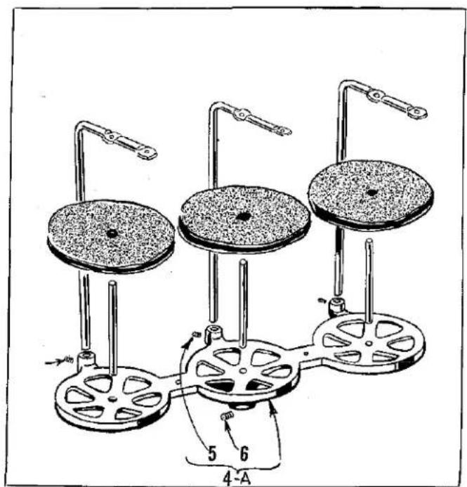
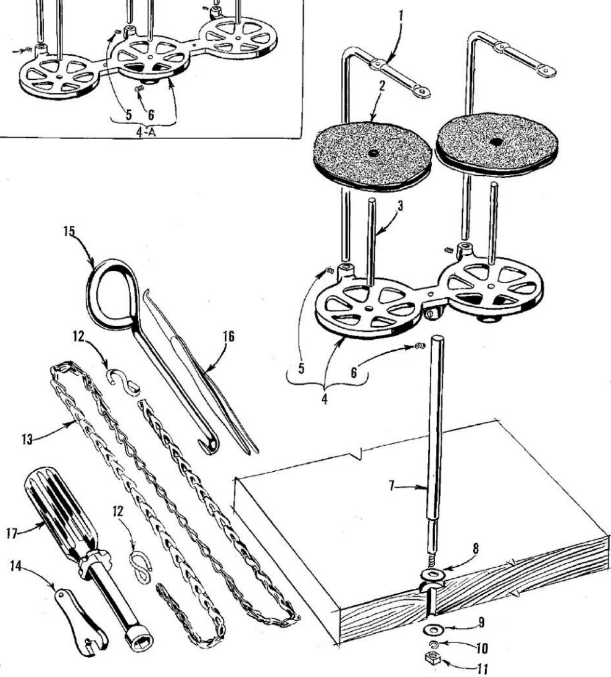
THREAD STAND AND MISCELLANEOUS TOOLS
| Ref.No. | PartNo. | Description | Amt.Req. |
| 1 | 21113 F | Thread Stand Eyelet, for Styles 39500 FJ, JJ- | 2 |
| 21113 F | Thread Stand Eyelet, for Style 39500 FL- | 3 | |
| 2 | 21104 V | Pad, for thread cone, for Styles 39500 FJ, JJ- | 2 |
| 21104 V | Pad, for thread cone, for Style 39500 FL- | 3 | |
| 3 | 69 S | Spool Pin, for Styles 39500 FJ, JJ- | 2 |
| 69 S | Spool Pin, for Style 39500 FL- | 3 | |
| 4 | 21130 W-2 | Cone Support, for Styles 39500 FJ, JJ- | 1 |
| 4A | 21130 W-3 | Cone Support, for Style 39500 FL- | 1 |
| 5 | 22650 CB-4 | Screw, for thread stand eyelet- | 2 or 3 |
| 6 | 22650 CE-6 | Screw, for cone support- | 1 |
| 7 | 21104 AA | Thread Stand Rod- | 1 |
| 8 | 652 J-24 | Washer, for thread stand rod- | 1 |
| 9 | 652 J-16 | Washer, for thread stand rod- | 1 |
| 10 | WA9 A | Lock Washer, for thread stand rod- | 1 |
| 11 | 651 A-16 | Nut, for thread stand rod- | 1 |
| 12 | 660-264 | "S" Hook, for treadle chain- | 2 |
| 13 | 421 D-34 | Treadle Chain, 34 inches long- | 1 |
| 14 | 116 | Wrench, for 9/32 inch nut- | 1 |
| 15 | 21227 BF | Feed Eccentric Extractor Hook- | 1 |
| 16 | 660-240 | Thread Tweezers- | 1 |
| 17 | 21388 AU | Socket Wrench, for 3/8 inch nuts holding feedeccentrics- | 1 |
ACCESSORIES AVAILABLE AS EXTRAS (Not Illustrated)
| 21233 GG | Light Fixture Assembly, including blue lens, machine mounting for machines driven by "Electro Drive" which supplies the current. |
| 21261 M-350 | No. 1 "V" Belt, 35 inches long, for fully submerged individual power table installations. |
| 21261 M-370 | No. 1 "V" Belt, 37 inches long, for semisubmerged individual power table installations. |
| 21261 M-390 | No. 1 "V" Belt, 39 inches long, for nonsubmerged individual power table installations. |
| 21377 BM | Tray, 1.3/4 inches high, for semisubmerged installations. |
| 21695 U | Finger Protector. |
| 28604 L | Can of Oil, 16 fluid ounces of Spec. 83 oil. |
| 39598 | Knife Grinder, complete. |
| 52978 J | Chip Disposal Chute. |
| Belt Slot to Right Edge of Board | Cloth Plate to Front Edge of Board | ||
| 21371 UH | Individual Power Table | ||
| 21371 PJ-48 | Table Top, 48 x 20 x 1 3/4 inches, for nonsubmerged individual power table installation - no chip chute; | 14 inch | 3/8 inch |
| 21371 RD-48 | Table Top, same except nonsubmerged with chip chute; | 7 1/2 inch | 3 inch |
| 21371 RF-48 | Table Top, same except nonsubmerged no chip chute; | 7 1/2 inch | 3/8 inch |
| 21371 RJ-48 | Table Top, same except semisubmerged - with chip chute; | 10 1/2 inch | 2 1/4 inch |
| 21371 RL-48 | Table Top, same except semisubmerged - with chip chute; | 7 1/2 inch | 2 1/4 inch |
| 21371 WL-48 | Table Top, same except fullysubmerged - with chip chute; | 7 1/2 inch | 2 1/4 inch |
| 21371 RC-47 3/4 | Table Top, 47 3/4 x 16 x 1 3/4 inches, for nonsubmerged lineshaft installation - no chip chute; | 7 1/2 inch | 3/8 inch |
| 21371 RE-47 3/4 | Table Top, same except nonsubmerged with chip chute; | 7 1/2 inch | 3 inch |
| 21371 RH-47 3/4 | Table Top, same except semisubmerged - with chip chute; | 7 1/2 inch | 2 1/4 inch |
NUMERICAL INDEX OF PARTS
| Part No. | Page No. | Part No. | Page No. | Part No. | Page No. |
| WA9 A | 31 | 8372 A | 23, 29 | 22747 B | 21 |
| 22 KH | 25 | 12538 | 29 | 22758 E | 23 |
| 28 | 21, 23, 25, | 12865 | 29 | 22768 B | 23, 29, |
| 30-92 Blk | 21 | 12957 E | 23 | 22769 B | 21 |
| 40-46 | 21, 23, | 14077 | 23, 27, 29, | 22798 | 29 |
| 50-774 Blk | 23 | 21104 V | 31 | 22806 A | 29 |
| 51-103 Blk | 19 | 21104 AA | 31 | 22819 | 29 |
| 51-228 Blk | 21 | 21113 F | 31 | 22847 B | 29 |
| CO67 E | 21 | 21130 W-2 | 31 | 22892 B | 27 |
| 69 S | 31 | 21130 W-3 | 31 | 22894 C | 25 |
| 73 X | 29 | 21227 BF | 31 | 22894 D | 21 |
| 77 | 25 | 21388 AU | 31 | 22894 AD | 19, 25, |
| 77 Q | 21 | 22503 F | 25 | 29126 DF | 25 |
| 86 X | 19 | 22513 | 23 | 29477 GW | 19 |
| 87 | 23 | 22524 | 27 | 29477 JM | 21 |
| 88 | 29 | 22528 | 23 | 29477 JN | 21 |
| 88 B | 23 | 22541 | 19 | 39142 G | 21 |
| 90 | 19 | 22541 A | 21 | 39151 | 25 |
| 95 | 21 | 22562 A | 19, 25, | 39501 K | 19 |
| 97 | 25 | 22564 G | 25 | 39501 DG | 19 |
| 97 A | 21 | 22565 | 19, 25, | 39501 EE | 19 |
| 116 | 31 | 22565 F | 19, 21, 23, | 39503 A | 23 |
| 138 | 19 | 22565 H | 25 | 39503 C | 23 |
| 154 GAS | 23 | 22566 B | 29 | 39503 D | 23 |
| 258 | 21, 23, | 22569 | 19, 23, | 39505 J | 23 |
| 376 A | 29 | 22569 A | 19 | 39505 K | 23 |
| 421 D-34 | 31 | 22569 B | 23, 29, | 39505 AJ | 23 |
| 482 C | 25 | 22569 C | 23 | 39505 AK | 23 |
| 604 | 23 | 22569 D | 19, 29, | 39508 A | 25 |
| 605 | 29 | 22569 G | 23 | 39508 B | 25 |
| 627 | 29 | 22571 E | 19 | 39520 L | 29 |
| 651 A-16 | 31 | 22585 A | 27 | 39521 C | 21 |
| 652 J-16 | 31 | 22586 R | 19 | 39521 D | 21 |
| 652 J-24 | 31 | 22587 J | 21, 27, | 39524 J | 27 |
| 660-142 | 29 | 22588 A | 27 | 39524 AJ | 27 |
| 660-206 | 25 | 22596 E | 21, 23, | 39525 A | 27 |
| 660-207 | 23 | 22597 F | 29 | 39525 L | 27 |
| 660-240 | 31 | 22598 E | 29 | 39530 | 29 |
| 660-243 | 19 | 22650 CB-4 | 31 | 39532 A | 19 |
| 660-264 | 31 | 22650 CE-6 | 31 | 39534 G | 23 |
| 660-268 | 21 | 22653 B-12 | 27 | 39534 H | 23 |
| 666-94 | 21 | 22653 D-4 | 19 | 39534 R | 19 |
| 666-255 | 25 | 22657 D-12 | 19 | 39535 C | 23 |
| 667 D-8 | 19 | 22729 B | 27 | 39535 D | 23 |
| 1025 L | 25 | 22729 D | 25 | 39535 F | 23 |
| 1280 | 25 | 22729 E | 25 | 39535 J | 23 |
| 6042 A | 27 | 22738 | 27 | 39536 B | 23 |
| 7446 A | 25 | 22743 | 19 | 39536 C | 23 |
| 39536 D | 23 |
NUMERICAL INDEX OF PARTS
| Part No. | Page No. | Part No. | Page No. | Part No. | Page No. |
| 39536 E | 23 | 39556 M | 29 | 39590 G | 21 |
| 39536 AE | 23 | 39557 | 19 | 39590 H | 21 |
| 39538 | 23 | 39557 A | 19 | 39590 J | 21 |
| 39540 B-5 | 23 | 39557 B | 19 | 39590 K | 21 |
| 39540 K | 23 | 39557 C | 19 | 39590 N | 21 |
| 39541 A | 21 | 39557 E | 19 | 39590 P | 21 |
| 39543 | 25 | 39557 F | 19 | 39590 R | 21 |
| 39543 A | 25 | 39560 A | 25 | 39590 S | 21 |
| 39543 E | 25 | 39563 D | 29 | 39590 T | 21 |
| 39543 H | 25 | 39563 Z | 23 | 39591 A | 21 |
| 39543 K | 25 | 39568 A | 23 | 39591 B | 21 |
| 39543 M | 25 | 39568 B | 29 | 39591 G | 21 |
| 39543 P | 25 | 39568 D | 29 | 39591 H | 21 |
| 39543 R | 25 | 39568 E | 29 | 39591 K | 21 |
| 39543 S | 25 | 39568 G | 19 | 39592 AA | 29 |
| 39543 T | 25 | 39568 J | 19 | 39592 AB | 29 |
| 39543 U | 25 | 39568 L | 29 | 39592 AC | 29 |
| 39543 V | 25 | 39568 W | 29 | 39592 AD | 29 |
| 39544 | 25 | 39568 Y | 23 | 39592 AE-2 | 29 |
| 39544 B | 25 | 39570 J | 27 | 39592 AE-4 | 29 |
| 39544 D | 25 | 39571 B | 27 | 39592 AF | 29 |
| 39544 J | 25 | 39571 C | 27 | 39592 AG-3 | 29 |
| 39544 L | 21 | 39571 F | 27 | 39592 AH | 29 |
| 39544 S | 25 | 39572 A | 27 | 39592 AJ | 29 |
| 39544 U | 25 | 39573 A | 27 | 39592 AK | 29 |
| 39544 V | 25 | 39573 E | 27 | 39592 AL | 29 |
| 39549 J | 27 | 39573 H | 27 | 39592 AM | 29 |
| 39550 C | 27 | 39573 J | 27 | 39592 AR-8 | 29 |
| 39550 E | 27 | 39573 K | 21 | 39593 C | 19 |
| 39550 L | 27 | 39573 L | 21 | 39593 D | 19 |
| 39550 M | 27 | 39578 F | 19 | 39593 H | 19 |
| 39550 U | 27 | 39578 M | 23 | 39594 G | 19 |
| 39551 F | 23 | 39578 P | 23 | 39594 H | 19 |
| 39552 | 23 | 39578 U | 19 | 39594 N | 21, 23, 25, |
| 39552 C | 23 | 39580 AE | 27 | 39594 R | 19 |
| 39552 N | 21 | 39582 F | 19 | 39595 | 19 |
| 39552 P | 21 | 39582 K | 19 | 39597 L | 29 |
| 39552 R | 23 | 39582 V | 19 | 41071 G | 19 |
| 39555 | 29 | 39582 W | 19 | 43139 A | 29 |
| 39555 A | 29 | 39582 X | 19 | 43143 N | 25 |
| 39555 B | 29 | 39582 Y | 19 | 53634 C | 23 |
| 39555 C | 29 | 55235 D | 27 | ||
| 39555 D | 29 | 39582 AD | 19 | 55235 E | 27 |
| 39555 E | 21 | 39582 AE | 19 | ||
| 39555 F | 29 | 39582 AF | 19 | ||
| 39556 A | 19 | 39582 AG | 19 | ||
| 39556 D | 29 | 39590 | 21 | ||
| 39556 L | 29 | 39590 D | 21 |

FINEST QUALITY
UnionSpecial®
LEWIS and COLUMBIA
INDUSTRIAL SEWING MACHINES


SALES OFFICES AND REPRESENTATIVES
†Handle Union Special and Columble only.
†Handle Lewis and Columbia only.
All others handle Union Special, Lewis and Columbia with certain exceptions.
UNITED STATES
ALABAMA 35206, BIRMINGHAM, 732-84th Street, South, Lloyd D. Baldwin, Tel. 833-9904.
ALABAMA 36107, MONTGOMERY, 3223 Willow Lane Dr., (Zip Code 36110), Tommy Hendrix, Tel. 272-6667.
ARKANSAS 72203, LITTLE ROCK, P.O. Box 1783, James T. Taylor, Tel. (501) 376-3121.
★CALIFORNIA 90021, LOS ANGELES, 1100 E. Pico Blvd., Paul M. Mason, Mr., Tel. Madison 5-5828.
CALIFORNIA 94110, SAN FRANCISCO, 3420-25th Street Robert J. Voil, Tel. 415/826-6969.
†CALIFORNIA 94103, SAN FRANCISCO, Apparel City Sewing Machine Co., 1155 Mission St., Tel. Market T-6660.
COLORADO 80002, ARYADA, Casey's Sewing Machine Service, 5719 Reed St., Tel. 424-6630.
CONNECTICUT 06810, DANBURY, 22 Barnum Road, Robert W. Goines, Tel. 746-3652.
FLORIDA 33127, MIAMI, 2511-2515 N.W. 2nd Ave., Philip A. Coleman and E. A. Quinterro, Tel. 305-635-5922.
FLORIDA 33566, PLANT CITY, 506 N. Gordon St. James C. Morgan, Tel. 752-1829.
GEORGIA 30324, ATLANTA, 2120 Plasters Bridge Road, N.E., Merritt M. Ambrose, Mgr., Tel. 875-9237.
GEORGIA 30529, COMMERCE, Lakeview Drive, J. Tom Hanley, Tel. 335-4061, 3668 Admiral Drive (Chambles), Marshall Clouse, Tel. 451-0562.
GEORGIA 30030, DECATUR, 1713 Coventry Road, Joe V. Parker, Tel. 377-5559.
GEORGIA 31021, DUBLIN, 1615 Knox St., John W. Jones, Tel. 272-4663, P.O. Box 561, Salbar St. (Thomaston 30286) H. B. Gray.
★ILLINOIS 60610, CHICAGO. 400 N. Franklin St., Fred L. Koehler, Mgr., Tel. 644-6920.
KANSAS 66208, KANSAS CITY (PRAIRIE VILLAGE) 7351 Rosewood, Cleo C. Smith, Tel. HE 2-1705.
KENTUCKY 40207, LOUISVILLE, P.O. Box 7261, Raymond E. Hinton, Tel. 587-0042.
LOUISIANA 70458, NEW ORLEANS (SLIDELL) 375 Dorset Drive, Duane Bunger, Tel: 504/643-2484.
MARYLAND 21215, BALTIMORE, P.O. Box 2505, Ralph B. Foster, Tel. 727-8499.
MARYLAND 21204, BALTIMORE, J. Dashew, Inc., 417 W. Baltimore St., Tel. Lexington 9-1838.
★MASSACHUSETTS 02111, BOSTON, 179 Lincoln St., William E. Palm, Mgr., Tel. Liberty 2-0147.
MASSACHUSETTS 02368, RANDOLPH, P.O. Box B6, Roy T. Pedersen, Tel. 828-1412.
MASSACHUSETTS 02767, TAUNTON, P.O. Box #2 Raynham, Welter: P. Godak, Tel. VanDyke 2-6149.
MICHIGAN 48223, DETROIT, 14561 Auburn, John Joyce, Tel. 313-538-7256
MINNESOTA 55426, MINNEAPOLIS, 2095 Kelly Dr., Golden Valley, Minn., Leonard W. Kochler, Tel. 644-6236.
MISSISSIPPI 39209, JACKSON, 327 Eastview St., Jamie A. Boyotte, Tel. Fleetwood 5-1976. 3517 Payne Dr. J. W. Kaes, Tel. 601/939-3264.
MISSISSIPPI, 39862, PLANTERSVILLE, P.O. Box 657, J. D. Kelley.
\$MISSOUR! 64105, KANSAS CITY, Textile Machinery Co., 975 Broadway, Tel. Victor 2-9558.
MISSOURI 63114, ST LOUIS, 9022 Pallardy Lane, Carl E. McLaughlin, Tel. Chestnut 1-2368.
FNEW HAMPSHIRE 03060, NASHUA, P.O. Box 257, Herman E. Haberman Jr., Tel. Tuxedo 2-9698.
NEW JERSEY 07850, LANDING, 676 Rebo Road, Henry Behrens, Tel. 201-398-2749.
†NEW JERSEY 07032, NORTH ARLINGTON, 32M Garden Terrace, Joseph Loglisci, Tel. 991-8211.
NEW JERSEY 08091, WEST BÉRLIN, P.O. Box 26, Frank A. Neff, Tel. 767-4350.
NEW YORK 02110, LATHAM. 57 Sylvan Ave., Clarence A, Wheeler, Tel. 518-785-6371.
NEW YORK 14502, MACEDON, 3 Jupiter Way, James Halbohm, Tel. 986-4693.
★NEW YORK 10001, NEW YORK, 370 7th Ave., (Penn Terminal Bldg.), Jack R. LeTourneur, Mgr., Tel. Chickering 4-8800.
NEW YORK 14609, ROCHESTER, A. J. Adams Co., 1051 Culver Rd., Tel. Butler 8-7250.
NEW YORK 11553, UNIONDALE, 873 Henry St., Anthony Candell, Tel. Ivanhoe 3-7477.
NORTH CAROLINA 27407, GREENSBORO, 4216 Pannydale Dr., Harold E. Miller, Tel. 292-0734. 3005 Harte Place (27405) James Toler, Phone 919—274-7941.
NORTH CAROLINA 28501, KINSTON, 2810 Murray Hill Rd., Bunny D. Smith, Tel. 919/521-7509, 729 Jones Ave., Jerry W. Potta, Phone 919—527-4891.
OHIO 44109, CLEVELAND, 4914 Pearl Road, Cat & Sew Equipment Co Tel 661-590!
OHIO 43216, COLUMBUS, P.O. Box 37, Gerry Smith, Phone: 614/294-0222.
OKLAHOMA 73119, OKLAHOMA CITY, 2226 Southwest 53rd St., G. & Wiley, Tel 685-2836
OREGON, 97220, PORTLAND, 1950 N.E. 118th Ave. Robert E. Ritt. Phone: 503/771-2159 (Portland) 206/624-8083 (Seattle).
PENNSYLVANIA 18105, ALLENTOWN, P.O. Box 542, Luther D. Cassell, Tel. 797-2111.
PENNSYLVANIA 18015, BETHLEHEM, 1212 Camac St., Ed Deegan, Tel. 868-8204
PENNSYLVANIA 18003, BERWICK, 1013 E. 16th St., Donald McFadden, Tel. 752-2442.
PENNSYLVANIA 18411, CLARKS SUMMIT, 428 West Grove Ave., Joan J. Laßer, Tel. JUniper 7-2820.
★PENNSYLVANIA 19124, PHILADELPHIA, 4234 Macoletter Ave., Ben W. Merz, Mr., Tel. Gladstone 5-9300.
†PENNSYEVANIA 15670, NEW ALEXANDRIA. (Pittsburgh) R.D. No. 1, Box 26A, W. Dale Speer, Tel. 415—563-3589.
PENNSYLVANIA 17088, SCHAEFFERSTOWN, P.O. Box 217, David M. Bender, Tel. 949-3044.
PENNSYLVANIA 17404, YORK, P.O. Box 884, Harding T. Powell, 854-8040, P.O. Box 222 (Schuylkill Haven 17972) F. J. Bartosic.
SOUTH CAROLINA 29204, COLUMBIA, P.O. Box 4246, Virlyn R. Crisler, Tel. Sunset 7-0863.
SOUTH CAROLINA 29607, GREENVILLE, 25 Sir Abbot St., Orville W. Gregory, Tel. Cedar 9-5539. P.O. 3557, (Gastonia 29607) John Lawrence, Tel. 864-7546.
TENNESSEE, 37421, CHATTANOOGA, 1711 Roy Jo Circle, John W. Carter 615-892-1489, Rt. 4, Box 300 (Cleveland 37311) Bill Ott Tel. 615-4725.
TENNESSEE 38301, JACKSON, 1180 Hollywood Drive, Apt. 114, W. D. Compton, Tel. 901/427-5707, 1026 Wellsville Rd., (Memphis 38117) Harry McCarley
TENNESSEE 37919, KNOXVILLE, P.O. Box 10822 Horace E. Clinard, Tel. 588-1865, Rt. 4, Box 300 (Cleveland 37311) Bill OH, Tel. 615-4725,
TENNESSEE 37211, NASHVILLE, 5179 Ashley Dr., Roger L. Anderson, Tel. 615-833-0142; 1617 Lebanon (37210), Walter L. Rudd, Tel. 615-254-7538.
*TEXAS 75247, DALLAS, 6718 Oakbrook Blvd., P.O. Box 47424, J. H. Muir Mgr., Tel. 214/637-5990.
TEXAS 79926, EL PASO, P.O. Box 9573, Edward E. Smith, Tel. 598-2928.
TEXAS 76106, FT. WORTH, 1201 Altamont Dr., Arnold Stler-walt, Tel. 626-3183.
TEXAS 78213, SAN ANTONIO, Jerry Gregory, P.O. Box 13126, Tel. DI 2-6924.
UTAH 84105, SALT LAKE CITY, 1215 E. 13th South St., Larry F. Rosvall, Tel. IN 7-6931.
VIRGINIA 24006, Roanoke, P.O. Box 1151, P. C. Ebla, Tel. 703-362-5673.
VIRGINIA 23834, Colonial Heights, P.O. Box 277, Tom Traylor, Tel. 703-526-2855.
WASHINGTON, SEATTLE, Robert E. R11, Phone 206—624-3083.
CANADA
UNION SPECIAL MACHINE Co. of Canada, Ltd.
BRITISH COLUMBIA, N. BURNABY 2, James Murray, 1522 Madison Ave., Tel. MU 3-3917.
MANITOBA, WINNIPEG 2, Rm. 201, Whitla Bldg., 70 Arthur St., Oswald Borcharl, Tel. 204/943-4933.
★ONTARIO, TORONTO 2B, Peter Fowler, Mar.-Rep., 355 King St. West, Tel. Empire 6-2939.
★QUEBEC, MONTREAL 11, John Caschello, Mar., 9495 Charles de Latour St. Tel. 514/387-7191
FINEST QUALITY WORK
HIGHEST PRODUCTION ■ RATES
LOWEST ■ MAINTENANCE COSTS

natural_image
World map with latitude and longitude grid lines, showing continents and oceans (no text labels)WORLDWIDE SALES AND SERVICE
Union Special Corporation maintains sales and service facilities throughout the world. These offices will aid you in the selection of the right sewing equipment for your particular operation. Union Special Corporation representatives and service technicians are factory trained and are able to serve your needs promptly and efficiently. Whatever your location, there is a qualified representative to serve you.
Corporate Office:
One Union Special Plaza
Huntley, IL 60142
Phone: 847·669·5101
Fax: 847-669-1096
European Distribution Center:
Union Special GmbH
Raffleisenstrasse 3
D-71696 Möglingen, Germany
Tel: 49-07141-247-0
Fax: 49·7141·247·100
Brussels, Belgium
Charlotte, N.C.
El Paso, TX
Hong Kong, China
Huntley, IL
Leicester, England
Lille, France
Miami, FL
Milan, Italy
Möglingen, Germany
Montreal, Quebec
Osaka, Japan
Santa Fe Springs, CA
Other Representatives throughout
all parts of the world.

Finest Quality
Union Special® INDUSTRIAL SEWING EQUIPMENT
- IDENTIFICATION OF MACHINES
- APPLICATION OF CATALOG
- STYLES OF MACHINES
- OILING
- NEEDLES
- CHANGING NEEDLES
- THREAD STAND
- THREADING
- TO THREAD THE LOWER LOOPER
- TO THREAD THE UPPER LOOPER (Style 39500 FL)
- TO THREAD THE NEEDLE
- THREAD TENSION
- PRESSER FOOT PRESSURE
- FEED ECCENTRICS
- ASSEMBLING AND ADJUSTING SEWING PARTS
- SETTING THE NEEDLE
- SETTING THE REAR NEEDLE GUARD
- SETTING THE LOWER LOOPER
- SETTING THE FRONT NEEDLE GUARD
- SETTING THE SPREADER (Styles 39500 FJ and JJ)
- SETTING THE SPREADER (Styles 39500 FJ and JJ) (Continued)
- SETTING THE UPPER LOOPER (Style 39500 FL)
- SETTING THE FEED DOGS
- SETTING THE LOWER KNIFE
- SETTING THE UPPER KNIFE
- SETTING THE STITCH LENGTH
- SETTING THE STITCH LENGTH (Continued)
- SETTING THE PRESSER FOOT
- STARTING TO OPERATE
- THREAD TENSIONS
- SPECIAL ADJUSTMENTS
- TO REMOVE CRANKSHAFT
- TO REMOVE CRANKSHAFT (Continued)
- ORDERING REPAIR PARTS
- ILLUSTRATIONS
- IDENTIFYING PARTS
- USE GENUINE NEEDLES AND REPAIR PARTS
- TERMS
- TORQUE REQUIREMENTS
- UnionSpecial®
- SALES OFFICES AND REPRESENTATIVES
- UNITED STATES
- MARYLAND 21204, BALTIMORE, J. Dashew, Inc., 417 W. Baltimore St., Tel. Lexington 9-1838.
- CANADA
- WORLDWIDE SALES AND SERVICE
Brand : Union Special
Model : 39500JJ
Category : Peeler