
35800PZB32 - Sewing Machine Union Special - Free user manual and instructions
Find the device manual for free 35800PZB32 Union Special in PDF.

| Product Type | Industrial Sewing Machine (Double Lap Seamer) |
| Brand | Union Special |
| Model | 35800PZB32 |
| Style | Same as 35800DRUB with reverse teeth roller |
| Seam Specification | 401 LSc-3 (Double Locked Stitch) |
| Standard Gauge | 8 (1/8", 3.2mm) or 9 (9/64", 3.6mm) |
| Recommended Needle | 130GS, size 140/054 |
| Maximum Speed | 4500 RPM |
| Feed Type | Plain feed with upper driven roller (reverse teeth) |
| Roller Width | Narrow: 0.468" (15/32", 11.9mm) |
| Step Sewing Parts | 0.094 step |
| Oiling System | Automatic enclosed with filter type oil pump |
| Needle Thread Take-Up | Double disc looper thread take-up |
| Space in Front of Needles | 8" (203.2mm) |
| Left Needle Position | Front |
| Number of Needles | 2 or 3 (typically 3 for double lap seam) |
| Weight | Approximately 50 kg (estimated) |
| Dimensions (L x W x H) | Approximately 500 x 300 x 400 mm (estimated) |
| Power Source | Not specified; typically 0.5 kW electric motor |
| Typical Application | Seat seaming and in-out seaming on medium to heavy denim garments |
| Maintenance | Clean and oil regularly; use only recommended parts |
| Parts Kit | Kit 29480BEC for soft stitch conversion |
Frequently Asked Questions - 35800PZB32 Union Special
User questions about 35800PZB32 Union Special
0 question about this device. Answer the ones you know or ask your own.
Ask a new question about this device
Download the instructions for your Sewing Machine in PDF format for free! Find your manual 35800PZB32 - Union Special and take your electronic device back in hand. On this page are published all the documents necessary for the use of your device. 35800PZB32 by Union Special.
USER MANUAL 35800PZB32 Union Special
JUKI UnionSpecial
INSTRUCTIONS / ILLUSTRATED PARTS LIST

natural_image
Five different types of denim jeans arranged in a row, no text or symbols visible35800 LAPSEAMER WITH MECHANICAL DRIVE PULLER AND SPECIAL SOFT STITCH FORMATION PARTS
CATALOG NO. PT0601
FIRST EDITION SUPPLEMENT TO PT9804
STYLES 35800DNUB8 35800DNUB9 35800DNWB8 35800DNWB9 35800DRUB8 35800DRUB9 35800DRWB9 35800PZB32 35800PZB36
First Edition Copyright 2006
By
Union Special Corporation Rights Reserved In All Countries
Printed in U.S.A. May 2006
IDENTIFICATION OF MACHINES
Each UNION SPECIAL machine is identified by a style number, which is stamped into the style plate affixed to the middle of the machine under the tension assembly.
The serial number is stamped in the casting at the right rear base of the machine.
CLASS DESCRIPTION
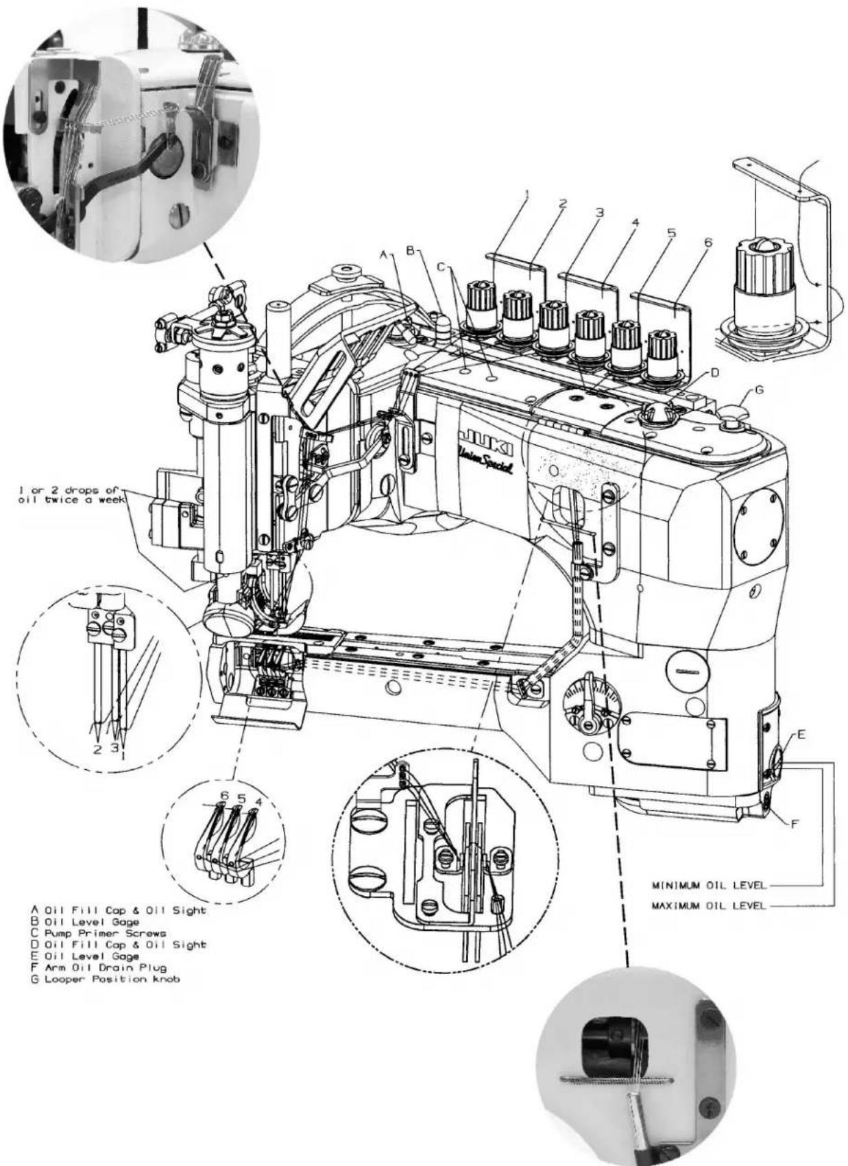
High Speed, Feed-Off-The-Arm High Throw Machines, Two and Three Needle, Left Needle In Front. Light Weight Presser Bar Mechanism, Adjustable Looper Avoid, Space in Front of Needles 8" (203.2 mm), Double Disc Looper Thread Take-Up, Automatic Enclosed Type Oiling System and Filter Type Oil Pump, Visual Sight Oil Action and Supply Gauges. Special soft stitch formation parts.
STYLE OF MACHINES
35800DNUB
DOUBLELAPSEAM. Three needle, high capacity, differential feed with upper driven roller feed. -Typical Application- For in and out seaming on heavy weight denim garments. Seam Specification 401 LSc-3. Standard gauge Numbers 8 [1/8", 3.2mm] and 9 [9/64", 3.6mm]. Recommended needle 130GS, size 140/054. Maximum recommended speed 4500 R.P.M.. .094 step sewing parts. .468 (15/32, 11.9mm) narrow roller.
35800DNWB
DOUBLE LAPSEAM. Three needle, high capacity, differential feed with upper driven roller feed. -Typical Application- For in and out seaming on heavy weight denim garments. Seam Specification 401 LSc-3. Standard gauge Numbers 8 [1/8", 3.2mm] and 9 [9/64", 3.6mm]. Recommended needle 130GS, size 140/054. Maximum recommended speed 4500 R.P.M.. .094 step sewing parts. .588 (19/32, 15.0mm) wide roller.
35800DRUBDOUBLELAPSEAM. Three needle, high capacity, plain feed, upper driven, roller feed. Feed Dogshave higher teeth on front. - Typical Application- For seat seaming, in and out seam on medium to heavy weight denim garments. Seam Specifications 401LSc-3. Standard gauge Numbers 8 [1/8", 3.2mm] and 9 [9/64", 3.6mm]. Recommended needle 130GS, size 140/054. Maximum recommended speed 4500 R.P.M.. .094 step sewing parts. .468 (15/32", 11.9mm) narrow roller.
35800PZB Same as 35800DRUB except with reverse teeth roller.
35800DRWB
DOUBLE LAP SEAM. Three needle, high capacity, plain feed, upper driven, roller feed (wide roller). Feeds have higher teeth on front of feeds. - Typical Application- For seat seaming, in and out seams on medium to heavy weight denim garments. Seam Specifications 401LSc-3. Standard gauge 9 [9/64", 3.6mm]. Recommended needle 130GS, size 140/054. Maximum recommended speed 4500 R.P.M.. .094 step sewing parts. .588" (19/32", 15mm) wide roller.
 |  |  |  |  |  | ||
| selytSIIA | SG0313 | 6 | mm2.7nm with center needle removed | 6.3 | 6.3:2dna3( | mm0.9 | MD054inraum |
| 00853 H C | ||||||
| DRA ETALPTAORHYTS | DNATS | ADNATS | HCTITSNOOLIIE | ORTER | TA | ALETAORHT |
| ELYTSEKHCAM | ETALP | KRAM | ||||
| 35824DN8 | 35800DNU8 | 35800DNUB8 | 29480BEB | 35824ED8 | ED8 | |
| 35824DN9 | 35800DNU9 | 35800DNUB9 | 29480BDY | 35824EC9 | EC9 | |
| 35824DX8 | 35800DNWB8 | 29480BEA | 35824DZ8 | DZ8 | ||
| 35824DX9 | 35800DNWB9 | 29480BDZ | 35824DZ9 | DZ9 | ||
| 35824DQ8 | 35800DRU8 | 35800DRUB8 | 29480BEC | 35824EF8 | EF8 | |
| 35824DQ9 | 35800DRU9 | 35800DRUB9 | 29480BED | 35824ED9 | ED9 | |
| 35824DQ8 | 35800PZ32 | 35800PZB32 | 29480BEC | 35824EF8 | EF8 | |
| 35824DQ9 | 35800PZ36 | 35800PZB36 | 29480BED | 35824ED9 | ED9 | |
| 35824DQW9 | 35800DRW9 | 35800DRWB9 | 29480BEH | 35824EF9 | EF9 | |

BALLOON STITCH PARTS
| Ref. | Amt. | ||
| No.: Part No. | Description | Req. | |
- 29480BEB Kit of Parts, for 35800DNUB8 1
- 29480BDY Kit of Parts, for 35800DNUB9 1
- 29480BEA Kit of Parts, for 35800DNWB8 1
- 29480BDZ Kit of Parts, for 35800DNWB9 1
- 29480BEC Kit of Parts, for 35800DRUB8, 35800PZB32 1
- 29480BED Kit of Parts, for 35800DRUB9, 35800PZB36 1
- 29480BEH Kit of Parts, for 35800DRWB9 1
-
35882K Front Cover 1
-
50658A Looper Thread Eyelet 1
-
29476CA Cast-Off Plate Assembly 1
-
35804B Cast-Off Plate 1
-
36204A Cast-Off 1
-
22KH Screw 2
-
52958C Eyelet 1
-
73A Screw 2
D. 52958F Eyelet 1
-
35853AN LooperThread Spring 1
-
35823D Double Disc Take-up Cam 1
-
22580 Screw 2
-
22704 Screw 2
-
29476CB Needle Thread Take-up Assembly 1
-
35804C Needle Thread Take-up 1
-
35804B Needle Thread Strike-off 1
-
25B Screw 2
-
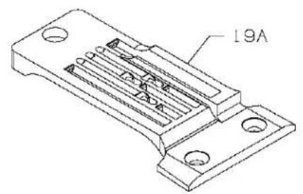
35824DN8 Throat Plate, I. D. marked "ED8", for 29480BEB kit of parts....1
- 35824DN9 Throat Plate, I. D. marked "EC9", for 29480BDY kit of parts .... 1
- 35824DQ8 Throat Plate, I. D. marked "EF8", for 29480BEC kit of parts .... 1
- 35824DQ9 Throat Plate, I. D. marked "ED9", for 29480BED kit of parts.... 1
19A. 35824DX8 Throat Plate, I. D. marked "DZ8", for 29480BEA kit of parts.... 1
- 35824DX9 Throat Plate, I. D. marked "DZ9", for 29480BDZ kit of parts....1
- 35824DQW9 Throat Plate, I. D. marked "EF9", for 29480BEH kit of parts .... 1
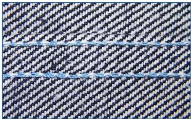
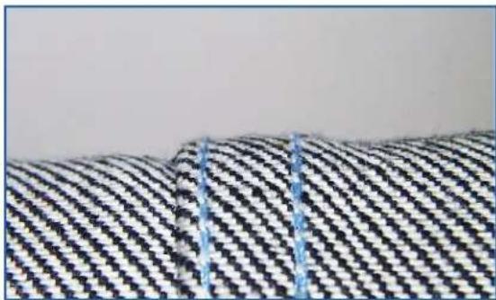
Appearance of Standard vs. Soft Double-locked Stitch
natural_image
Close-up of a woven fabric with diagonal striped pattern and two blue wavy lines (no text or symbols)
natural_image
Close-up of woven fabric with blue and white striped pattern, featuring two brown braided strips (no text or symbols)Standard Double-locked Stitch Soft Double-locked Stitch
natural_image
Close-up of a woven fabric with diagonal striped pattern and blue stitching (no text or symbols)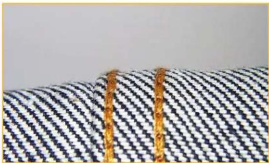
natural_image
Close-up of a patterned fabric with diagonal striped texture and two golden bands at the bottom (no text or symbols visible)NOTE:
THIS MANUAL IS USED FOR CHANGING THE STANDARD PARTS TO SOFT DOUBLE-LOCKED STITCH PARTS ON BOTH THE DIFFERENTIAL AND PLAIN FEED 35800 MACHINES. THE STEPS ARE THE SAME FOR BOTH MACHINE TYPES EXCEPT WHERE NOTED.
PROCEDURE FOR REMOVAL OF STANDARD STITCH PARTS
Step 1A. Remove screw for control lever connecting link. Remove 2 screws for front head cover, then remove cover. Remove control lever assembly and nipper plate assembly. Attach control lever assembly and nipper plate assembly to new cover supplied with kit.


Step 1B. Remove pressure regulating screw, spring plate and upper and lower leaf springs. Remove 9 screws for chamber cover, then remove cover and gasket. Remove 6 screws for front top cover, then remove cover and gasket. Remove 4 screws for main frame end cover, then remove cover and gasket.
REMOVAL PROCEDURE, continued
Step 1C. Remove screw for plastic oil reservoir, then remove reservoir.


Step 2. Remove 2 screws from cast off plate, then remove plate. Loosen but do not remove 2 screws for take up cam.
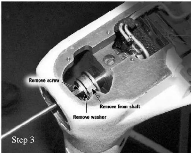
Step 3. Remove screw for stop shaft washer, then remove washer. Carefully slide looper drive connection from end of mainshaft.
NOTE: For differential feed machines, follow Steps 4A and 4B. For plain feed machines, go to Step 5.
Step 4A. Loosen 2 cap screws for feed lift eccentric assembly, and remove top half of eccentric strap. Note strap position when removing—strap must be reinstalled later in same position to avoid binding.


Step 4B. Loosen 2 screws in feed lift eccentric and 2 screws in feed drive eccentric just enough so that eccentrics will turn freely on shaft.
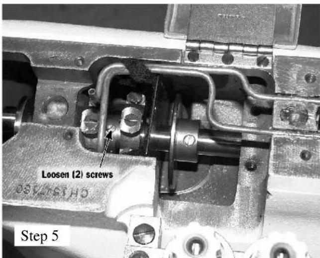
Step 5. Loosen 2 screws in the double feed eccentric assembly just enough so eccentric will move freely.
REMOVAL PROCEDURE, continued
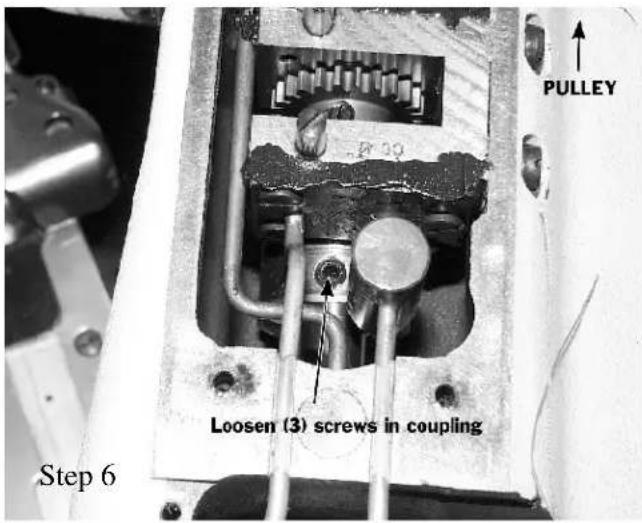
Step 6. Loosen 3 screws in mainshaft and crankshaft coupling just enough so that mainshaft will turn freely inside of coupling.
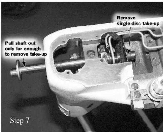
Step 7. Pull mainshaft out from front of machine only far enough so that take up cam can be removed. Remove take up cam.
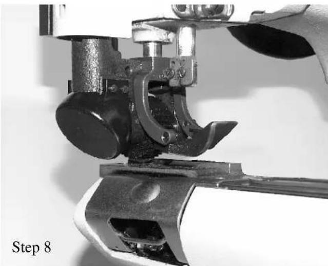
Step 8. Lift presser foot and roller assembly, and remove standard throat plate.
natural_image
Close-up of a mechanical device with a hand operating it, labeled 'Step 8' (no other text or symbols visible)PROCEDURE FOR INSTALLATION OF SOFT STITCH PARTS
Locate and identify new parts from kit.
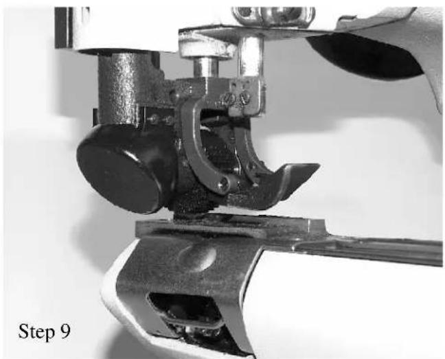
Step 9. Install new throat plate and release presser foot and roller assembly.
natural_image
Close-up of a mechanical device with a hand operating it, labeled 'Step 9' (no other text or symbols visible)
Step 10. Locate new double disc take up cam, and slide cam onto end of mainshaft with collar side toward the pulley end of the machine.
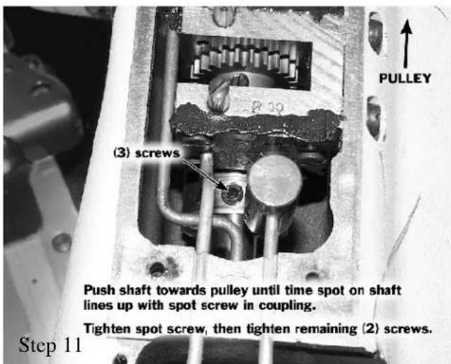
Step 11. Push mainshaft towards pulley end of machine until timing spot in the mainshaft aligns with spot screw in coupling. Tighten spot screw into spot of mainshaft and then tighten remaining 2 screws.
INSTALLATION PROCEDURE, continued
Note: For differential feed machines follow Steps 12A, 12B and 12C. For plain feed machines follow Step 13.
Step 12A. Align spot screw in feed lift eccentric with spot in mainshaft and tighten spot screw, then tighten remaining screw.

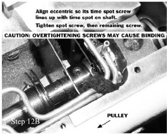
Step 12B. Align spot screw in feed drive eccentric with spot in mainshaft and tighten spot screw, then tighten remaining screw.
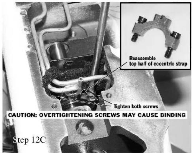
Step 12C. Locate top half of eccentric strap which was removed previously. Reassemble strap in same position as it was prior to removal, and tighten screws. After assembly turn machine over for several revolutions to make certain machine does not bind. If machine binds, check strap position and repeat step 15.
Step 13. Align spot screw in double feed eccentric assembly with spot in mainshaft and tighten spot screw, then tighten the remaining screw.

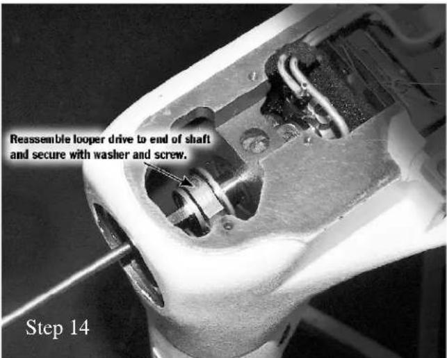
Step 14. Reassemble looper drive to end of mainshaft, replace washer and tighten in place with screw.
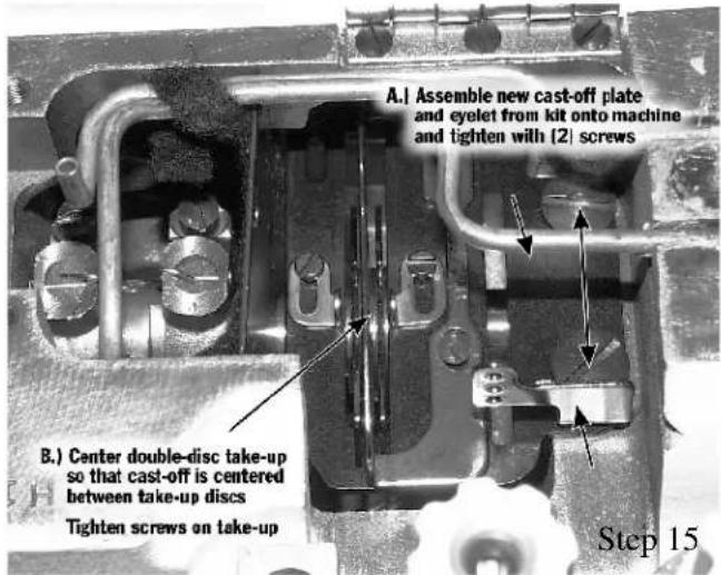
Step 15. A) Assemble new cast off plate and eyelet from kit and tighten with 2 screws. B) Center double disc take up so that cast-off plate is centered between the take up discs.
INSTALLATION PROCEDURE, continued
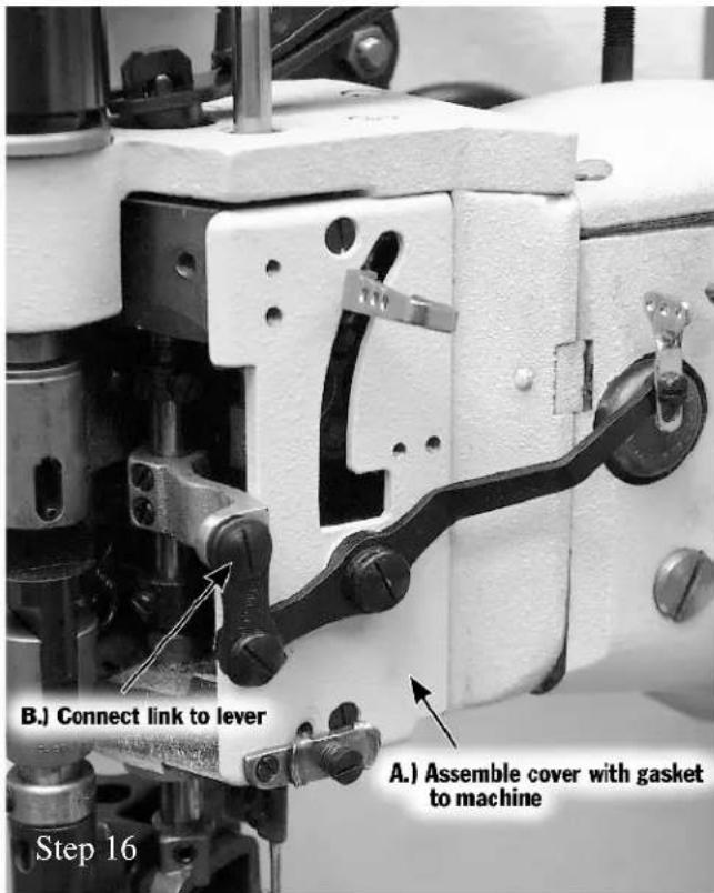
Step 16. A.) Assemble new front head cover and gasket to machine with its 2 screws. B) Attach connecting link to lever with its screw.
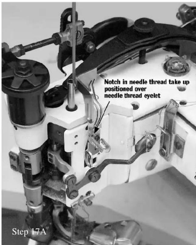
Step 17A. With needle bar at top of stroke, position new needle thread take-up so that notch in take-up fits over needle thread eyelet.
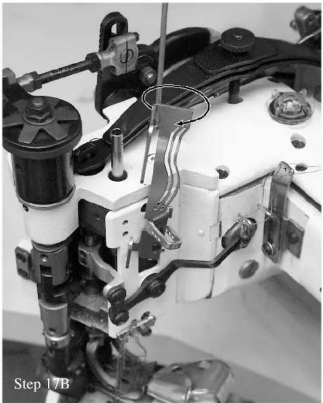
Step 17B. Rotate take-up clockwise, lower it into position over control lever, and attach to cover with its two screws.
natural_image
Close-up of a sewing machine needle and mechanical components, labeled 'Step 17B' (no readable text or symbols on the main subject)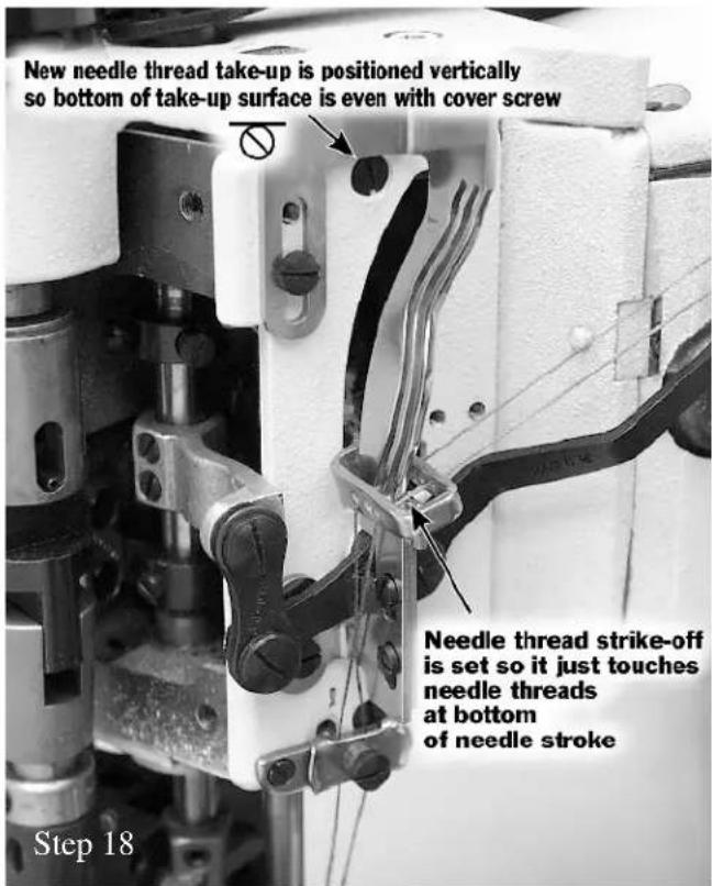
Step 18. Position new needle thread take-up vertically so bottom of take-up surface is even with top of cover screw. Thread machine so that one needle thread passes through each hole in needle lever thread eyelet.* Needle thread strike-off is set so it just touches needle threads at bottom of needle stroke.
*Same as standard threading.
INSTALLATION PROCEDURE, continued
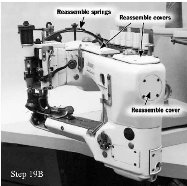
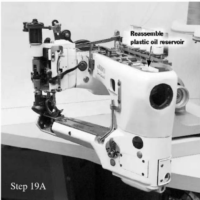
Step 19A. Reassemble plastic oil reservoir with its screw.
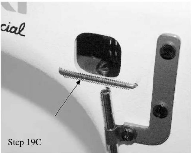
Step 19C. Remove Looper thread guide wire and slide spring from kit over the wire and then replace guide wire on machine.
Step 19B. Reassemble chamber cover, top cover, main frame end cover and presser foot tension springs.

Step 20 Set both looper thread pull-off eyelets maximum to the right. Set double disc take-up cam so that looper thread casts off from high point of cam when tips of the needles on down stroke are between bottom of throat plate and top of loopers. Thread one looper thread through each hole in new eyelet from kit.
Step 21 Set needle thread tensions to high, so that needle threads are pulled up very tight against material. Set looper thread tensions to low, so that maximum amount of looper thread is in the material.

Union Special Corporation
Corporate Office
One Union Special Plaza
Huntley, IL 60142
Phone: 847·669·5101
Fax: 847·669·4454
Union Special GmbH
EuropeanDistributionCenter
Raiffeisenstrasse 3
D-71696 Möglingen, Germany
Tel: 49• 07141• 247• 0
Fax: 49•07141•247•100
JUKI CORPORATION
INTERNATIONAL SALES DIVISION
8-2-1, KOKURYO - CHO
- JUKI UnionSpecial
- IDENTIFICATION OF MACHINES
- CLASS DESCRIPTION
- STYLE OF MACHINES
- 35800DNUB
- 35800DNWB
- 35800DRWB
- BALLOON STITCH PARTS
- Appearance of Standard vs. Soft Double-locked Stitch
- NOTE:
- PROCEDURE FOR REMOVAL OF STANDARD STITCH PARTS
- REMOVAL PROCEDURE, continued
- PROCEDURE FOR INSTALLATION OF SOFT STITCH PARTS
- INSTALLATION PROCEDURE, continued
Brand : Union Special
Model : 35800PZB32
Category : Sewing Machine