
DMX-WL1 - Audio/Video Accessories SONY - Free user manual and instructions
Find the device manual for free DMX-WL1 SONY in PDF.


| Product Type | Wireless HDMI Transmitter/Receiver System (BRAVIA Wireless Link) |
| Model | DMX-WL1 (Transmitter: DMX-WL1T, Receiver: DMX-WL1R) |
| Brand | Sony |
| Wireless Technology | 5 GHz band, OFDM modulation |
| Maximum Transmission Distance | Approximately 65 ft (20 m) |
| Minimum Distance Between Units | 1 ft (30 cm) |
| Video Inputs (Transmitter) | 4 HDMI (IN 1-4), 1 Component (IN 5: YPbPr + L/R audio) |
| Video Output (Receiver) | 1 HDMI OUT |
| Audio Output (Transmitter) | 1 Digital Audio Out (Optical) |
| Supported Video Resolutions | 480i, 480p, 720p, 1080i (1080p not supported) |
| Audio Support | Two-channel linear PCM, Dolby Digital, DTS (max 3 Mbps) |
| Power Requirement | 120 V AC, 60 Hz (each unit) |
| Power Consumption (in use) | 10 W each (20 W total) |
| Power Consumption (standby) | Less than 1.5 W each |
| Receiver Dimensions (W x H x D) | 190 x 34 x 139 mm (7 1/2 x 1 3/8 x 5 1/2 in) |
| Receiver Weight | 0.45 kg (1.0 lb) |
| Transmitter Dimensions (with stand) | 118 x 229 x 226 mm (4 3/4 x 9 1/8 x 9 in) |
| Transmitter Weight (with stand) | 0.87 kg (1.9 lb) |
| Remote Control Frequency | 2.4 GHz band |
| IR Blaster | 3 jacks on transmitter for controlling external equipment |
| HDMI Control (Control for HDMI) | Receiver power syncs with TV via HDMI CEC |
| Cleaning Instructions | Use dry soft cloth; mild soap solution for stubborn stains; no solvents |
| Safety Certification | FCC Part 15 Class B, ICES-003 |
| Supplied Accessories | Receiver, transmitter, 2 AC adapters, 2 power cords, remote, 2 AA batteries, 2 IR Blaster Y-cables, 1 IR Blaster cable, transmitter stand with screw, wall-mount bracket, TV mounting bracket, HDMI cable, minijack cable, warranty card, reference guide, startup guide, 3 plastic fasteners |
Frequently Asked Questions - DMX-WL1 SONY
User questions about DMX-WL1 SONY
0 question about this device. Answer the ones you know or ask your own.
Ask a new question about this device
Download the instructions for your Audio/Video Accessories in PDF format for free! Find your manual DMX-WL1 - SONY and take your electronic device back in hand. On this page are published all the documents necessary for the use of your device. DMX-WL1 by SONY.
USER MANUAL DMX-WL1 SONY
BRAVIA Wireless Link
Reference Guide
The Reference Guide contains troubleshooting, specifications, and safety related information.
DMX-WL1
Owner's Record
The model, serial numbers and the date of manufacture are written on the rating labels. They are located at the bottom of the transmitter and the receiver.
Record these numbers in the spaces provided below. Refer to them whenever you call upon your Sony dealer regarding this product.
Transmitter Receiver
Model No. DMX-WL1T DMX-WL1R
Serial No. ____ ____
WARNING
To reduce the risk of fire or electric shock, do not expose the equipment to rain or moisture.

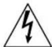
This symbol is intended to alert the user to the presence of uninsulated "dangerous voltage" within the product's enclosure that may be of sufficient magnitude to constitute a risk of electric shock to persons.

This symbol is intended to alert the user to the presence of important operating and maintenance (servicing) instructions in the literature accompanying the appliance.
The equipment shall not be exposed to dripping or splashing and no objects filled with liquids, such as vases, shall be placed on the equipment.
Do not install this equipment in a confined space, such as a bookshelf or similar unit.
CAUTION
To prevent electric shock, do not use this polarized AC plug with an extension cord, receptacle or other outlet unless the blades can be fully inserted to prevent blade exposure.
NOTIFICATION
This equipment has been tested and found to comply with the limits for a Class B digital equipment, pursuant to Part 15 of the FCC Rules. These limits are designed to provide reasonable protection against harmful interference in a residential installation. This equipment generates, uses and can radiate radio frequency energy and, if not installed and used in accordance with the instructions, may cause harmful interference to radio communications. However, there is no guarantee that interference will not occur in a particular installation. If this equipment does cause harmful interference to radio or television reception, which can be determined by turning the equipment off and on, the user is encouraged to try to correct the interference by one or more of the following measures:
□Reorient or relocate the receiving antenna.
□Increase the separation between the equipment and receiver.
□Connect the equipment into an outlet on a circuit different from that to which the receiver is connected.
□Consult the dealer or an experienced radio/TV technician for help.
Pursuant to FCC regulations, you are cautioned that any changes or modifications not expressly approved in this manual could void your authority to operate this equipment.
For Customers in Canada
This Class B digital apparatus complies with Canadian ICES-003.
Trademark Information
"BRAVIA" and are trademarks of Sony Corporation.
PLAYSTATION is a registered trademark and "PS3" is a trademark of Sony Computer Entertainment Inc.
HDMI
This equipment incorporates High-Definition Multimedia Interface (HDMI™) technology. HDMI, the HDMI logo and High-Definition Multimedia Interface are trademarks or registered trademarks of HDMI Licensing, LLC.
This product incorporates copyright protection technology that is protected by U.S. patents and other intellectual property rights. Use of this copyright protection technology must be authorized by Macrovision corporation, and is intended for home and other limited consumer uses only unless otherwise authorized by Macrovision. Reverse engineering or disassembly is prohibited.
NOTE ON AC POWER ADAPTER (EADP-16ABA)
Warning
To reduce the risk of fire or electric shock, do not expose this apparatus to rain or moisture.
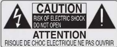

This symbol is intended to alert the user to the presence of uninsulated “dangerous voltage” within the product’s enclosure that may be of sufficient magnitude to constitute a risk of electric shock to persons.

This symbol is intended to alert the user to the presence of important operating and maintenance (servicing) instructions in the literature accompanying the appliance.
To prevent fire or shock hazard, do not place objects filled with liquids, such as vases, on the apparatus.
Do not install this equipment in a confined space, such as a bookshelf or similar unit.
□Please ensure that the wall outlet is installed near the equipment and shall be easily accessible.
□Be sure to use the supplied AC power adapter and power cord.
☐Do not use any other AC power adapter. It may cause a malfunction.
□Connect the AC power adapter to an easily accessible wall outlet.
□Do not coil the AC
power cord
around the
AC power
adapter. The
core w
may be cut
and/or it may
cause
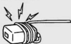
malfunction of the equipment.
☐Do not touch the AC power adapter with wet hands.
□If you notice an abnormality in the AC power adapter, disconnect it from the wall outlet immediately.
☐The set is not disconnected from the AC power source as long as it is connected to the wall outlet, even if the set itself has been turned off.
Important Safety Instructions
1) Read these instructions.
2) Keep these instructions.
3) Heed all warnings.
4) Follow all instructions.
5) Do not use this equipment near water.
6) Clean only with dry cloth.
7) Do not block any ventilation openings. Install in accordance with the manufacturer's instructions.
8) Do not install near any heat sources such as radiators, heat registers, stoves, or other equipment (including amplifiers) that produce heat.
9) Do not defeat the safety purpose of the polarized or grounding-type plug. A polarized plug has two blades with one wider than the other. A grounding type plug has two blades and a third grounding prong. The wide blade or the third prong are provided for your safety. If the provided plug does not fit into your outlet, consult an electrician for replacement of the obsolete outlet.
10) Protect the power cord from being walked on or pinched particularly at plugs, convenience receptacles, and the point where they exit from the equipment.
11) Only use attachments/accessories specified by the manufacturer.
12) Use only with the cart, stand, tripod, bracket, or table specified by the manufacturer, or sold with the equipment. When a cart is used, use caution when moving the cart/equipment combination to avoid injury from tip-over.

13) Unplug this equipment during lightning storms or when unused for long periods of time.
14) Refer all servicing to qualified service personnel. Servicing is required when the equipment has been damaged in any way, such as power-supply cord or plug is damaged, liquid has been spilled or objects have fallen into the equipment, the equipment has been exposed to rain or moisture, does not operate normally, or has been dropped.
USE
AC power cord and other cables
If you damage the AC power cord or other cables, it may result in a fire or an electric shock. If the AC power cord or any other cables is damaged, stop using it at once and contact the Sony service center.
☐Do not place the equipment where the power cord and cables are subject to wear or abuse.
☐Do not pinch, bend, or twist the cord excessively. The core lines may be bared and cut, and cause a short-circuit, resulting in a fire or an electric shock.
☐Do not convert or damage the power cord and cables.
☐Do not allow anything to rest on or roll over the power cord and cables.
□Do not pull the power cord and cables.
☐Do not move the equipment with the power cord and cables plugged in.
□Keep the power cord and cables away from heat sources.
□Be sure to grasp the plug when disconnecting the power cord and cables.
☐Do not place the equipment in an area where the cables may become entangled and catch on your feet or hands.
Wall outlet
Do not use a poor fitting outlet. Insert the plug fully into the outlet. If it is loose, it may cause arcing and result in a fire. Contact your electrician to have the outlet changed.

Cable wiring
For your safety, unplug the AC power cord when wiring cables. Take care not to catch your feet on the cables. It may damage the equipment.
Electric shock
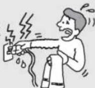
Do not touch the AC power cord or the equipment with a wet hand. If you plug/unplug the AC power cord from the equipment with a wet hand, it may cause electric shock.
Lightning
For added protection for this equipment during a lightning storm, or when it is left unattended and unused for long periods of time, unplug it from the wall outlet. This will prevent damage to the equipment due to lightning and power line surges.
Small accessories
Keep small accessories out of children's reach.
Use only the specified accessories with this product.
CLEANING
□Clean the AC power plug regularly.
□If the plug is covered with dust and it picks up moisture, its insulation may deteriorate and result in a fire.
□Unplug the AC power cord when cleaning this equipment. If not, it may result in electric shock.
□Clean the casing of the equipment with a dry soft cloth. Stubborn stains may be removed with a cloth slightly moistened with a solution of mild soap and warm water. Never use strong solvents such as thinner or benzine for cleaning.
□If using a chemically pretreated cloth, please follow the instruction provided on the package.
□Dust the ventilation holes with a dry cloth.

(continued)
VENTILATION
The holes on the side of the equipment are provided for necessary ventilation. To ensure reliable operation of the equipment, and to protect it from overheating, these ventilation holes must never be blocked or covered.
Unless proper ventilation is provided, the equipment may gather dust and get dirty. For proper ventilation, observe the following:
□ Never block the ventilation holes by placing the equipment on a bed, sofa, rug or other similar surface.
□Never place the equipment in a confined space, such as a bookcase or built-in cabinet, unless proper ventilation is provided.
Leave some space around the equipment as shown below. Otherwise, air-circulation may be inadequate and cause overheating, which may cause a fire or damage to the equipment.
Transmitter
Horizontal

Vertical
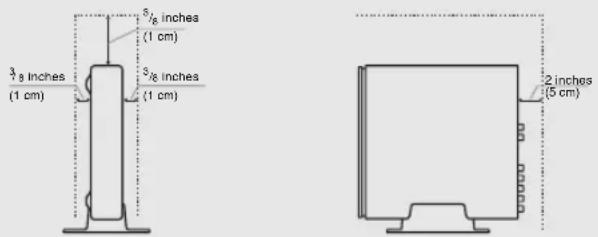
Receiver
Horizontal

Wall-mounting

Objects and ventilation holes
Never push objects of any kind into the equipment through the ventilation holes as they may touch dangerous voltage points or short out parts that could result in a fire or an electric shock. Never spill liquid of any kind on the equipment.
Do not place any objects on the equipment.
INSTALLATION
☐The equipment should be installed near an easily accessible power outlet.
☐Do not install the equipment in a hot or humid place, or in a place subject to excessive dust or greasy vapor.
□Avoid operating the equipment at temperatures below 41°F (5°C).
□When mounted to the back of the TV, do not use the receiver as a handle to pick up the TV set.
□Make sure that the cord and connected cables are placed so that tripping or stumbling may be avoided.
SERVICING
Damage requiring service
If the surface of the equipment cracks, do not touch the equipment until you unplug the AC power cord.
Otherwise electric shock may result.
Servicing
Do not attempt to service the equipment yourself since opening the cabinet may expose you to dangerous voltage or other hazards. Refer all servicing to qualified service personnel.
Replacement parts
When replacement parts are required, be sure to have the service technician certify in writing that he/she has used replacement parts specified by the manufacturer that have the same characteristics as the original parts.
Unauthorized substitutions may result in a fire, an electric shock or other hazards.
Safety check
Upon completion of any service or repairs to the equipment, ask the service technician to perform routine safety checks (as specified by the manufacturer) to determine that the equipment is in safe operating condition, and to so certify. Should the equipment not be repairable, ask a qualified service technician to dispose of the equipment.
For Customers in Canada
To prevent radio interface to the licensed service, this equipment is intended to be operated indoors and away from windows to provide maximum shielding. Equipment (or its transmit antenna) that is installed outdoors is subject to licensing.
For Customers in U.S.A.
FCC Part15E Cautions sentence
Only use this wireless equipment indoors.
Radio-Frequency Exposure Statement
This equipment complies with FCC/IC radiation exposure limits set forth for an uncontrolled environment.
This equipment should be installed and operated with minimum distance 20cm between the radiator and your body (excluding extremities: hands, wrists and feet).
This transmitter must not be co-located or operating in conjunction with any other antenna or transmitter.
Contents
Important Safety Instructions ....3
Overview
Welcome to the World of Wireless Link ^ ......6
Optimal Environment for Placement of the Units 6
Checking Accessories....6
Overview of the Button, Parts and Indicators ....7
Receiver Unit....7
Transmitter Unit....8
Overview of the Remote Control....10
TV Button Descriptions....10
Transmitter and External Equipment Button Descriptions....11
Using the Setup Menu
Setup Description....13
IR Blaster....13
Language....14
IR Code List ....15
Other Information
Attaching the Transmitter Unit Stand....17
Attaching the Receiver Unit 17
Attaching the Receiver Unit to the Rear of the TV....17
Place the Receiver Unit Stand-alone Near the TV 18
Installing the Receiver Unit on the Wall....19
Specifications....20
Troubleshooting....21

Startup Guide (separate volume)
The Startup guide explains how to connect, setup and use your wireless link.

Customer Support
http://www.sony.com/tvsupport
On-line Registration
United States
http://productregistration.sony.com
Canada
http://www.SonyStyle.ca/registration
Welcome to the World of Wireless Link®
Thank you for purchasing this Sony BRAVIA® Wireless Link. This product provides the capability to transmit HD video and audio from your AV sources to your compatible BRAVIA HDTV wirelessly. You can use the supplied remote control to operate your TV as well as your connected equipment. The Wireless Link supports connection for up to four HDMI sources and 1 component source.
Optimal Environment for Placement of the Units
Follow the suggestions below to create an optimal environment for your new Sony BRAVIA Wireless Link. Proper placement of the receiver and transmitter units will ensure a strong Wireless LINK LEVEL for superior performance.
• Use one system per room, placing the transmitter and receiver units for each system in the same room.
- If you use a 5 GHz WLAN or cordless phone, place those in a different room.
- Do not place either unit on a metallic rack.
- Place the transmitter unit as high up as possible.
- Maximum operating distance is approximately 20 m or 65 feet, depending on the environment.
- Be sure to keep at least 1 foot (30 cm) minimum distance between the transmitter and receiver units.
Checking Accessories
After unpacking, check that all the following items have been included:
- Receiver unit (1)
- Transmitter unit (1)
- AC power adapter (2)
- AC power cord (2)
- Remote control (1)
- Size AA battery (2)
- IR Blaster cable (Y-cable) (2)
- IR Blaster cable (1)
- Stand for the transmitter unit (1)
- Screw for stand (1)
• Wall-Mount bracket (1)
• TV Mounting bracket (1) - HDMI cable (1)
- Minijack cable for service (1)
- Warranty card (1)
• Reference Guide (this manual) (1) - Startup Guide (1)
- Plastic Fastener for TV Mounting bracket (3)
Overview of the Button, Parts and Indicators
Receiver Unit
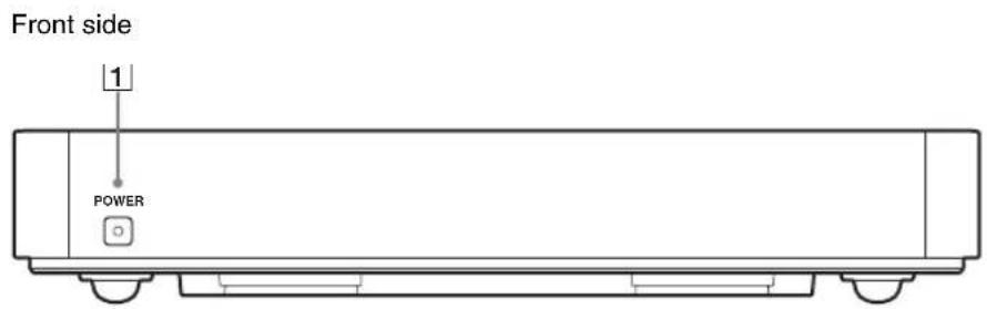

Item Description
1 POWER / POWER LED
Press to turn the receiver unit on and off, if Control for HDMI of the TV is Off. Lights up green when the receiver unit is turned on.

- If POWER LED of the receiver unit does not light up, confirm Control for HDMI setting of the TV is On.
- The power of the receiver unit turns on or off in conjunction with TV, if Control for HDMI setting of the TV is On and the unit is connected to the TV by HDMI cable.
- When Control for HDMI is enabled on your TV, the power of the receiver unit will follow the power state of the TV. When the TV is turned on or off, the receiver unit will also turn on or off. To manually control the power of the receiver unit using the receiver's POWER button, you must turn off the TV's Control for HDMI.
- If Control for HDMI of the TV is Off, you must turn the power of the receiver unit on or off by pressing the POWER button on the unit.
- The supplied remote control cannot be used to turn on or off the receiver unit separately from the TV.
2 DC IN 9V
Connects to the supplied AC power adapter with AC cord.
③ HDMI OUT Connects to any HDMI input on the TV. HDMI (High-Definition Multimedia Interface) provides an uncompressed, all-digital audio/video interface between the receiver unit and the TV.

- Be sure to use only an HDMI cable that bears the HDMI logo.
4/5 SERVICE
These jacks are for service only.
Transmitter Unit
Front side
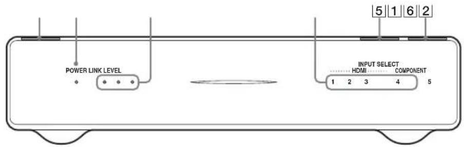
Rear side
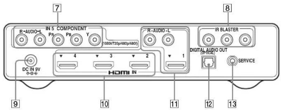
Item Description
| 1 POWER Press to turn the transmitter unit on and off. | |
| 2 POWER LED | Lights up in green when the transmitter unit is turned on. |
| 3 LINK LEVEL LED | Lights up in green to indicate the quality of the wireless signal between the receiver unit and transmitter units. |
| 4 INPUT SELECT LED | Lights up in green to indicate the input selected. |
| 5 CONNECT | Press to switch wireless channels when LINK LEVEL LED is low. |
| 6 INPUT SELECT | Press to select an input. |
| 7 IN 5 COMPONENT R-AUDIO-L/ (1080i/720p/480p/ 480i) | Connects to your equipment's component video (YPBPR) and audio (L/R) jacks. Component video (YPBPR) supports 480i, 480p, 720p and 1080i formats. |
| 8 IR BLASTER | Connects the supplied IR Blaster cables to any of the 3 IR BLASTER jacks. |
| 9 DC IN 9V | Connects to the supplied AC power adapter with AC cord. |
| Item Description | |
| 10 IN 2/3/4 HDMI | Connects to HDMI equipment, such as a set-top box, DVD player, Blu-ray Disc Player or AV receiver. |
| 11IN 1 HDMI R-AUDIO-L | If the equipment has a DVI jack and not an HDMI jack, connect the DVI jack to the IN 1 HDMI (with DVI-to-HDMI cable or adapter (not supplied)) jack, and connect the audio jack to the AUDIO IN (L/R) jacks of IN 1 HDMI.When using an HDMI signal without audio, be sure to also connect the audio cable. |
  | |
| These units support 480i, 480p, 720p and 1080i formats. The 1080p format is not supported.Be sure to use only an HDMI cable that bears the HDMI logo.Using a PC with this product is not supported. | |
| 12 DIGITAL AUDIO OUT (OPTICAL) | Connects to the optical audio input of your digital audio equipment that is PCM/Dolby Digital compatible. This unit supports Linear PCM and compressed audio format, such as Dolby Digital Audio, DTS audio, with a maximum bitrate of 3 Mbps or less. If the connected equipment and TV support compressed audio formats, the transmitter unit will output compressed audio. |
| 13 SERVICE This jack is for service only. | |
Overview of the Remote Control
TV Button Descriptions
Operate your TV using the following buttons.
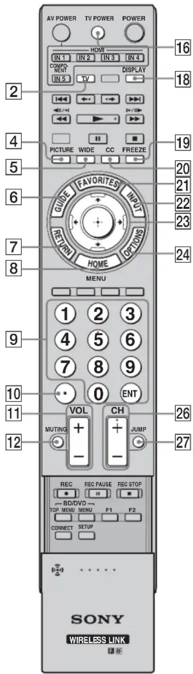
| Button Description | |
| 2 TV function button | The function button indicator lights up momentarily when pressed. You must first press the TV function button to operate the TV. |
| 4 PICTURE Press to change the picture mode. | |
| 5 WIDE Press to change the wide mode. | |
| 6 GUIDE | Press to open the TV Guide On screen system when available on your TV. |
| 7 RETURN | Press to go back to the previous screen or exit from the screen when displaying menu items and settings. |
| 8 HOME Press to display the TV Home menu. | |
| 9 0-9, ENT | Press 0-9 to select a channel; the channel changes after two seconds. Press ENT to change channels immediately. |
| 10 | Use with 0-9 and ENT to select digital channels. For example, to enter 2.1, press 2, and ENT. |
| 11 VOL +/- | Press to adjust the volume. |
| 12 MUTING | Press to mute the sound. Press again or press VOL + to restore the sound. |
| 16 TV POWER | Press to turn the TV on and off. |
| 18 DISPLAY | Press to display the current input information. |
| 19 FREEZE | Press once to display a frozen image with the current program in a window. Press again to return to the current program. |
| 20 CC | Press to turn closed captions on and off. |
| 21 FAVORITES | The favorite channel list appears depending on the TV. |
| 22 INPUT Press to select the input of the TV. | |
| 23 ↑/↓/←/→, ⊕ | Press ↑/↓/←/→ to move the on-screen cursor. Press ⊕ to select/confirm an item. |
| 24 OPTIONS | Press to display options menus. |
| 26 CH +/- | Press to scan through channels. To scan quickly through channels, press and hold down either +/- |
| 27 JUMP | Press to jump between two channels. |

- Point the remote control directly at the IR sensor on your TV.
- Some of the buttons illustrated here may be different or may not be available on your Sony TV remote control.
If the button is not on the supplied remote control, then use the remote control supplied with your TV.

• The 5 button, ▶ and CH + have
a tactile dot. Use them as
a reference when operating these units.
Transmitter and External Equipment Button Descriptions
When using the remote control to operate the transmitter unit and connected external equipment, the following button operations are available.
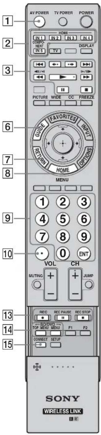
| Button Description | |
| 1 AV POWER | Press to turn the external equipment on and off after selecting an input using the input select buttons 2. |
| 2 IN 1/2/3/4 HDMI, IN 5 COMPONENT input select buttons | Press one of the input select buttons to select and control equipment connected to the corresponding input. The input select button indicator lights up momentarily when pressed to show which external equipment the remote control is operating. See the Startup Guide for programming the remote control. |
| 3 IN 1/2/3/4 HDMI, IN 5 COMPONENT operating buttons | • ◀◀◀/▶▶-: Goes to the beginning of the previous/next title/chapter/scene/track.• ↗: Replays the scene/briefly fast forwards the scene.• ◀◀◀/▶▶: Fast reverses/fast forwards the disc when pressed during playback.• ▶: Plays a disc at normal speed.• ||: Pauses the playback.• ■: Stops the playback. |
| 6 GUIDE | Press to display the Digital Electronic Program Guide (EPG) when the satellite receiver or cable box is selected. |
| 7 RETURN | Press to go back to the previous screen or exit from the screen when displaying menu items and settings. |
| 8 HOME (MENU) | Press to display menus of selected external equipment. |
| 9 0-9, ENT | For a set-top box, press 0-9 to select a channel. Press ENT to change channels immediately.For Blu-ray Disc or DVD, etc., press 0-9 as number key entry. Press ENT to confirm. |
| 10 ○ | For a set-top box, use with 0-9 and ENT to select digital channels. For example, to enter 2.1, press 2, 😊 1 and ENT.For Blu-ray Disc or DVD, etc., use with 0-9. |
| 13 DVR/VCR record buttons | REC ●: Press to record. Pressing this button alone starts the recording process.REC PAUSE ||: Press to pause the recording.REC STOP ■: Press to stop the recording. |
| 14 BD/DVD TOP MENU/ BD/ DVD MENU | Press to display the top menu of the BD/DVD disc. Press to display the BD/DVD disc menu. |
| 15 CONNECT | Press to switch to another wireless channel if the LINK LEVEL is low or the picture is noisy or the sound quality is diminished. |

- You must setup the IR Blaster before you can use external equipment (see page 13).
- Button functionality may differ depending on your equipment. If some functions do not work, then use the remote control supplied with your equipment.
(continued)

| Button | Description |
| 17 POWER Press to turn the transmitter unit on and off. | |
| The receiver unit does not turn on or off by pressing POWER. | |
| 18 DISPLAY | Press to display the current input information of selected external equipment. |
| 20 CC Press to turn closed captions of selected external equipment on and off. | |
| 21 FAVORITES | The favorite channel list will appear if supported by the external equipment. |
| 22 INPUT | Press to select the input of the external equipment. |
| 23 ↑/↓/←/→, ⊕ | Press ↑/↓/←/→ to move the on-screen cursor of selected external equipment. Press Ⓞ select/confirm an item. |
| 24 OPTIONS | Press to display the options menu of selected external equipment. The listed options vary depending on the input source. |
| 25 Color buttons | When the color buttons are available, an operation guide appears on the screen. Follow the operation guide to perform a selected operation. |
| 26 CH +/- | Press to scan through channels of selected external equipment. |
| 27 JUMP | Press to jump between two channels of selected external equipment. |
| 28 F1/F2 | Press to select the function of the selected external equipment. |
| 29 SETUP | Press to display the Setup menu for this product (see page 13). |

- Button functionality may differ depending on your equipment.
If some functions do not work, then use the remote control supplied with your equipment.
Using the Setup Menu
Use the Setup menu to change the Language or IR Blaster settings.

1 Press SETUP to display the Setup menu.
2 Press /// to highlight an item, and press to confirm.
3 Press SETUP to exit.
Setup Description

IR Blaster
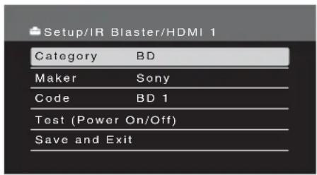
Set up the IR Blaster to control external equipment connected to the transmitter unit with the supplied remote control. For details, see the supplied Startup Guide.
| Category | Select the category from Cable Box, Satellite, VCR, DVD, BD or Receiver. |
| Maker Select the manufacturer of your equipment from the list.Select Enter code... to enter codes for equipment not listed (for code list, see page 15). | |
| Code Select the code from the list (see page 15).For Sony products, most of the codes appear as text. | |
| Test (Power On/Off) | Check that the code is correct by powering on or off the equipment attached to the selected input.If the equipment's supplied remote control has both a POWER ON and a POWER OFF button, the Test Power (On/Off) function might not work to test the IR code.Select Save and Exit, then test if any other remote buttons will operate your equipment. |
| Save and Exit | Save the setting and exit the Setup menu. |
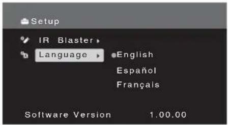
Language
Select a language from English, Español and Français.
IR Code List
Cable Box
| Manufacturer Code | |
| Sony Cable 1(2177),Cable DVR(2181) | |
| ABC 0003, 0237, 0008,0033 | |
| ADB 2586 | |
| Amino 1822 | |
| Digeo 1187 | |
| GeneralInstrument | 0476, 0810, 0003 |
| GoldStar 0144 | |
| Hamlin 0273 | |
| Jerrold 0476, 0810, 0003 | |
| Motorola 1376, 0476, 0810,1187 | |
| Myrio 1822 | |
| Oak 0019 | |
| Pace 0237, 1877, 0877,0008, 1060, 1068,1577 | |
| Panasonic 0000, 0008, 0144,0107, 1488 | |
| Pioneer 1877, 0877, 0144,0533, 1500, 1782 | |
| Regal | 0273 |
| Samsung | 0144, 0003, 0000,1060, 1666, 2015 |
| Scientific Atlanta | 1877, 0877, 0477,0237, 0003, 0000,0008, 1510 |
| Starcom | 0003 |
| Toshiba | 0000, 1509 |
| Zenith | 0000, 0008, 0525 |
Satellite
| Manufacturer Code | |
| Sony Satellite 1(1639),0853 | |
| Bell ExpressVu | 0775, 1170 |
| DirecTV | 1377, 0566, 1639,1142, 0247, 0749,1749, 0819, 1856,1076, 1108, 1109,1392, 1414, 1442,1609 |
| Dish NetworkSystem | 0775, 1505, 1005,1170, 1775 |
| Echostar | 0775, 1505, 1005,0853, 1170, 1323,1409, 1775 |
| GE | 0566 |
| Hitachi | 0819, 0749, 1250,1284, 1518 |
| Hughes NetworkSystems | 1142, 0749, 1749,1442 |
| JVC | 0775, 1170, 1775,1793, 1797 |
| LG | 1226, 1414 |
| Magnavox | 0722 |
| Mitsubishi | 0749 |
| Manufacturer Code | |
| Motorola | 0856 |
| Panasonic 0247, 0701, 1304, 1404 | |
| Philips 1142, 0775, 0749, 1749, 0819, 0856, 1076, 0722, 0853, 0200, 0887, 1114, 0173, 1442, 1672, 1743, 0133 | |
| RCA 0566, 0775, 1142, 0855, 0143, 1291, 1392, 1442 | |
| Samsung | 1377, 1142, 1276, 1108, 1109, 0853, 1206, 1442, 1609 |
| Tivo | 1142, 1442 |
| Toshiba | 0749, 1749, 0790, 1284, 1285, 1501, 1516, 1530 |
| Uniden | 0722 |
| Zenith | 1856, 0856 |
VCR
| Manufacturer Code | |
| Sony VCR 3(2184),VCR 1(1232),VCR 2(1546),DVR 1(2181),DVR 2(2182),DVR 3(2183),0035, 0048, 0047,0000, 0067, 0046,0226, 1972 | |
| Emerson | 0037, 0035, 0184,0039, 0240, 0045,0000, 0121, 0043,0209, 0072, 0002,0278, 0348, 0479,0593, 1593 |
| Go Video | 0240, 0432, 0526,0614, 1137 |
| Goldstar | 0037, 0035, 0039,0000, 0209, 0278,0038, 0225, 0226,1137 |
| Hitachi | 0000, 0035, 0037,0081, 0240, 0045,0042, 0041, 0046,0089, 0593, 1037,2613 |
| JVC | 0067, 0184, 0081,0045, 0041, 1162 |
| Magnavox | 0035, 0037, 0048,0039, 0081, 0240,0000, 0149, 0226,0563, 0593, 0618,0642, 1593 |
| Memorex | 0035, 0162, 0037,0048, 0039, 0047,0240, 0000, 0104,0209, 0072, 0278,0046, 0307, 0348,0479, 1037, 1048,1162, 1262 |
| Manufacturer Code | |
| Mitsubishi | 0067, 0060, 0048,0047, 0081, 0000,0042, 0043, 0041,0075, 0173, 0214,0443, 0642, 1631 |
| NEC | 0104, 0035, 0037,0048, 0067, 0041,0278, 0038, 0040,0050, 1137 |
| Panasonic 1062, 0035, 0162,0000, 0225, 0226,0614, 0616, 0837,1162, 1262, 1562 | |
| Philips 0035, 0162, 0048,0081, 0045, 0000,0209, 0226, 0563,0593, 0616, 0618,0739, 1081, 1181 | |
| RCA 0060, 0035, 0048,0240, 0045, 0000,0042, 0149, 0226,0880, 2613 | |
| ReplayTV | 0614, 0616 |
| Sanyo 0047, 0048, 0240,0000, 0104, 0067,0046, 0159, 0348,0479, 1137 | |
| Sharp | 0048, 0037, 0047,0000, 0209, 0848,1048 |
| Sylvania | 0035, 0081, 0000,0043, 0593, 1593 |
| Symphonic | 0000, 0240, 0002,0593, 1593 |
| Tivo | 0739, 0618 |
| Toshiba | 0045, 0081, 0240,0000, 0042, 0067,0043, 0209, 0041,0432, 0742, 1008,1972, 1988 |
| Zenith | 0039, 0037, 0000,0209, 0041, 0278,0479, 1137, 1139 |
DVD
| Manufacturer Code | |
| Sony DVD 1(1033), DVD/VCR(0864), DVD 3(1070), DVD 2(1069), 0573, 0630 | |
| CyberHome | 0714, 0816, 1023, 1024, 1129, 1502 |
| Denon | 1634, 0490, 0634 |
| Harman/Kardon | 0702 |
| Hitachi | 0573, 0664, 0695, 0713, 1247, 1664, 1748 |
(continued)
| Manufacturer | Code |
| Insignia 1268 | |
| JVC 0623, 0503, 0539,0558, 0867, 1164,1275, 1550, 1590,1591, 1592, 1594,1597, 1602 | |
| Kenwood 0534, 0490 | |
| LG 0741, 0591, 0869,1600, 2135 | |
| LiteOn 1058, 1416 | |
| Microsoft 2083, 0522 | |
| Mitsubishi 1521, 0521, 0713,1629 | |
| Onkyo 0627, 0503, 0792,1769 | |
| Panasonic 0490, 0503, 0571,0703, 1632, 1641,1762 | |
| Philips 0539, 0503, 2056,0646, 0675, 1260,1267, 1340, 1354,1506, 2084, 2093 | |
| Pioneer 0571, 0490, 0525,0142, 0631 | |
| RCA 0522, 0571, 0822,1769 | |
| Samsung 0573, 0490, 0744,0199, 0820, 1044,1075, 1470, 1599,1635, 1748, 2069 | |
| Sharp 0630, 0675, 0713,0752, 1256, 1556,1642, 2250 | |
| Sylvania | 0675, 0630, 0821,1268 |
| Toshiba | 0503, 0573, 0539,0695, 1154, 1503,1510, 1588, 1595,1608, 1639, 1769,1854 |
BD
| Manufacturer | Code |
| Sony BD 1(1516),BD 2(2178),BD 3(2180) | |
| LG 0741 | |
| Panasonic 1641 | |
| Philips 2084 | |
| Pioneer 0142 | |
| Samsung 0199 | |
| Sharp 2250 | |
Receiver
| Manufacturer | Code |
| Sony DVD AV System | |
| 1(1622), AV | |
| Receiver(2172), | |
| DVD AV System | |
| 4(1858), DVD AV | |
| System 3(1658), | |
| DVD AV System | |
| 2(1558) | |
| Aiwa | 0121, 1189, 1269, |
| 1089, 1641 | |
| Bose | 1229, 0639, 1933 |
| Denon | 1360, 0121, 1104, |
| 1142, 1306, 2857 | |
| Harman/Kardon | 0110, 1189, 1289, |
| 1304, 1306, 1310 | |
| Hitachi | 1801 |
| Insignia 1077 | |
| JVC 0074, 0531, 1374, | |
| 1495 | |
| Kenwood 1313, 1569, 0186 | |
| LG 1293 | |
| Marantz | 1189, 1269, 0128, |
| 0744, 1089, 1289 | |
| McIntosh | 1289 |
| Onkyo 1320, 1298, 1805 | |
| Panasonic 1308, 1518, 0367, | |
| 1288, 1309, 1316, | |
| 1548, 1633, 1763, | |
| 1764, 1779 | |
| Philips 1189, 1269, 0391, | |
| 1089, 1266, 1289, | |
| 1673 | |
| Pioneer 1023, 0150, 0186, | |
| 0244, 0531, 0630, | |
| 1384, 1459,1935, | |
| 1986 | |
| RCA 1609, 1023, 0531, | |
| 1154, 1390, 1459, | |
| 1511 | |
| Samsung 1295, 1304, 1500 | |
| Sharp 0186, 0653, 1634 | |
| Sherwood 1077, 0491, 0502, | |
| 0653, 1423, 1653 | |
| Yamaha 0176, 1023, 0186, | |
| 1276, 1331, 1376 | |
| If the code for your equipment is not listed, please visit http://www.sonystyle.com/dmxwl1 for a complete list of supported codes. | |
Other Information
Attaching the Transmitter Unit Stand
The transmitter unit can also be used vertically with the supplied stand.
1 Match the Guide Pin on the center of the stand and the screw hole on the right side of the transmitter unit.

2 Secure the screw.

Attaching the Receiver Unit
Attaching the Receiver Unit to the Rear of the TV
1 Attach the supplied TV Mounting bracket to the bottom left side of the TV rear panel.
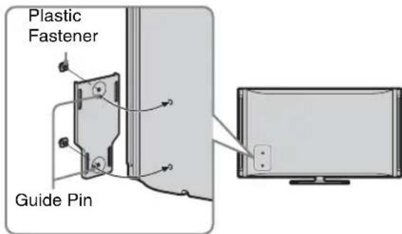
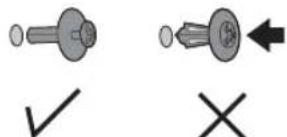
Insert the two Plastic Fasteners (supplied) into the holes to hold the TV Mounting bracket in place. Push the head of the Plastic Fastener with your finger until it clicks.

- Do not push the head of the Plastic Fastener until you have inserted the fastener into the hole on the TV.
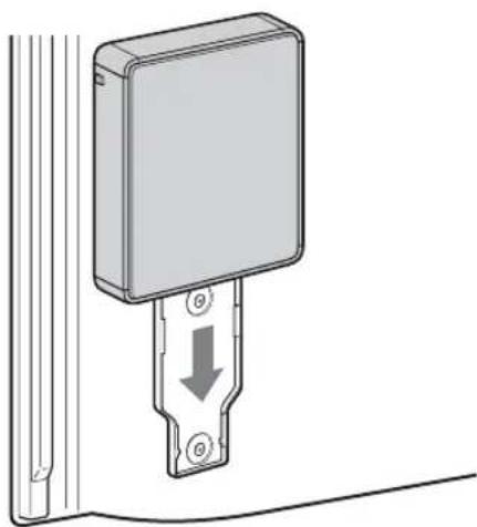
2 Align the slider on the bottom of the receiver unit with the groove of the TV Mounting bracket.

natural_image
Technical diagram showing a mechanical assembly with a bracket and mounting bracket, no text or symbols present
• To remove the bracket from the TV, use a Phillips screw driver (not supplied) to loosen the Plastic Fasteners. (continued)
3 Slide the receiver unit onto the bracket.
natural_image
Diagram of a wall-mounted electronic device with a downward arrow indicating a component (no text or symbols present)If the Wireless LINK LEVEL is low, the receiver unit can also be attached on the top right side of the rear TV panel which may provide better reception. In this case, attach the receiver unit by rotating 180 degrees.
Remove the receiver unit from the TV Mounting bracket on the rear TV panel, remove the TV Mounting bracket/Plastic Fasteners using a Phillips Screwdriver, remove the screws holding the adapter and rotate 180 degrees, then secure the screws again, attach the TV Mounting bracket and the receiver unit.

natural_image
Technical diagram of a mechanical component with mounting holes and internal channel (no text or symbols)Remove the screws

natural_image
Diagram of a rectangular electronic device with a central connector and circular arrows indicating rotation (no text or symbols)Rotate 180 degrees

natural_image
Technical diagram of a mechanical component with pins and internal cavity (no text or symbols)Secure the screws

- If no Guide Pins or screw holes are found on the rear TV panel, it is not designed to mount the receiver unit to the TV. In case of small TV, the Wall-Mount bracket of the TV might interfere with the receiver unit. If this is the case, place the receiver unit horizontally on a table or stand.
Place the Receiver Unit Stand-alone Near the TV
If the Wireless LINK LEVEL is still low, place the receiver unit horizontally near the TV. Find a location where all LINK LEVEL LEDs are lit.

natural_image
Line drawing of a flat-screen computer monitor with front panel and rear panel (no text or symbols)
- Be sure to remove the receiver unit from the back of the TV before moving the TV.
Installing the Receiver Unit on the Wall
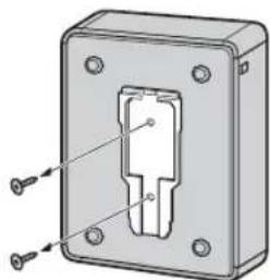
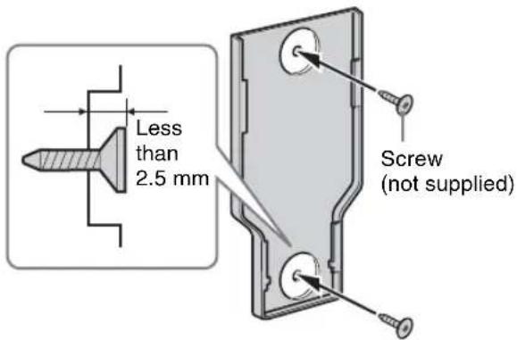
The receiver unit can be installed on a wall with the supplied Wall-Mount bracket. Be sure to use qualified contractors for installation.
For installation, use appropriate screws for the wall.
1 Install the supplied Wall-Mount bracket on the wall.
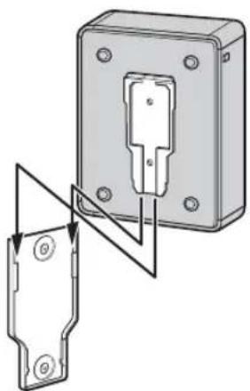
2 Align the slider on the bottom of the receiver unit with the groove of the Wall-Mount bracket.
natural_image
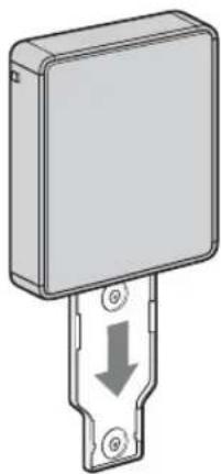
Technical diagram of a mechanical device with two components and directional arrows indicating assembly or alignment (no text or symbols present)3 Slide the receiver unit onto the bracket.
natural_image
Diagram of a rectangular electronic device with a downward arrow and mounting base (no text or symbols)Specifications
Receiver unit (DMX-WL1R)
| Input/Output jacks | |
| HDMI OUT | HDMI: Video: 480i, 480p, 720p, 1080i / Audio: Two channel linear PCM 32, 44.1 and 48 kHz, 16, 20 and 24bits, IEC61937 compressed audio format with a maximum bitrate of 3 Mbps or less. |
| SERVICE | For service use only. |
| DC IN | DC (9 V) |
| Power and others | |
| Power requirement | 120 V AC, 60 Hz |
| Power consumptionin use | 10 W |
| in standby | less than 1.5 W |
| Dimensions (W × H × D) (mm)(inches) | 190 × 34 × 139 7^1/_2 × 1^3/_8 × 5^1/_2 |
| Mass | 0.45 kg1.0 lb. |
Transmitter unit (DMX-WL1T)
| Input/Output jacks | |
| IN 5 COMPONENT | YPBPR (Component Video): Y: 1.0 Vp-p, 75 ohms unbalanced, sync negative / PB: 0.7 Vp-p, 75 ohms / PR: 0.7 Vp-p, 75 ohms / Signal format: 480i, 480p, 720p, 1080iAUDIO: 500 mVrms / Impedance: 47 kilohms |
| IN 1/2/3/4 HDMI | HDMI: Video: 480i, 480p, 720p, 1080i / Audio: Two channel linear PCM 32, 44.1 and 48 kHz, 16, 20 and 24bits, IEC61937 compressed audio format with a maximum bitrate of 3 Mbps or less.AUDIO (IN 1 HDMI only): 500 mVrms / Impedance: 47 kilohms |
| DIGITAL AUDIO OUT (OPTICAL) | Optical Digital Audio Output (PCM or IEC61937 compressed audio format with a maximum bitrate of 3 Mbps or less) |
| IR BLASTER | 3.5 mm Mini jack |
| SERVICE | For service use only. |
| DC IN | DC (9 V) |
| Power and others | |
| Power requirement | 120 V AC, 60 Hz |
| Power consumptionin use | 10 W |
| in standby | less than 1.5 W |
| Dimensions (W × H × D)with stand (mm)(inches) | 118 × 229 × 226 4^3/_4 × 9^1/_8 × 9 |
| without stand (mm)(inches) | 210 × 50 × 226 8^3/_8 × 2 × 9 |
| Masswith stand | 0.87 kg1.9 lb. |
| without stand | 0.82 kg1.8 lb. |
| Frequency range | 5 GHz band |
| Modulation | OFDM |
| Maximum transmission distance | Approximately 65 feet (20 m), depending on the home environment. |
| Minimum transmission distance | 1 foot (30 cm) |
| Remote control | 2.4 GHz band |
| Supplied accessories | See page 6. |

- Design and specifications are subject to change without notice.
Troubleshooting
| If you have questions, service needs, or require technical assistance related to the use of your Sony BRAVIA Wireless Link, please visit our website or call one of the following numbers: | http://www.sony.com/tvsupport1-866-918-2485 for US Support1-877-899-SONY(7669) for Canadian Support |
Condition Explanation/Solution
| The POWER LED of the receiver unit does not light up | Make sure the AC power cord and the AC power adapter are connected securely.Turn the TV power on.SetControl for HDMIof the TV toOn.If theControl for HDMIsetting on the TV isOff, you must turn on or off the receiver unit by pressing thePOWERbutton of the unit. |
| The receiver unit displays nothing on the TV | Check the connection of HDMI cable between the receiver unit and the TV.Check the HDMI input selection of the TV. |
| The receiver unit displays a message on the TV “Unable to communicate with transmitter.” | Make sure the power of the transmitter unit is on.Put the transmitter unit near the receiver unit.If you use a cordless phone, try turning off the power or moving it away from the units.If you use 5 GHz wireless LAN, try turning off the power or moving it away from the units. |
| The receiver unit displays a message on the TV “Unable to communicate with transmitter.” and the LINK LEVEL LED of the transmitter unit is still blinking | Put the transmitter unit near the receiver unit.Try to install the receiver unit in an alternate location.Try to find the best place and direction of the transmitter unit and the receiver unit.Remove the objects between the transmitter unit and the receiver unit.If you use a cordless phone, try turning off the power or moving it away from the units. |
| LINK LEVEL LED is less than three | Confirm the receiver unit is turned on.Check the connection of the cable between the equipment and the transmitter unit.Check the connected equipment is turned on. |
| The receiver unit displays a message on the TV “This signal is not supported by the transmitter.” | Set the resolution of the equipment to 480i, 480p, 720p or 1080i before connecting to the unit.If you currently use equipment connected directly to your TV with 1080p resolution, make sure to change the equipment’s resolution to 1080i or less before connecting it to the transmitter unit.For PL AY STATION®3, press and holdPOWERfor several seconds from standby to reset the resolution to 480p (HDMI) and 480i (Component). You may also use the PS3 menu to set the output resolution to 1080i or less before connecting to the transmitter unit.PC resolutions are not supported by this product.Non-standard signals may not work on the IN 5 COMPONENT input. |
| Condition Explanation/Solution | |
| Poor picture or diminished sound quality | Because of the wireless transmission, the quality of the picture is not the same as HDMI connection.Press CONNECT to search for a better wireless channel.Move the transmitter unit closer to the receiver unit.Try to install the receiver unit in an alternate location.Try to find the best placement and direction of the transmitter unit and the receiver unit.Remove the objects between the transmitter unit and the receiver unit.If you use a cordless phone, try turning off the power or moving it away from the units.If you use 5 GHz wireless LAN, try turning off the power or moving it away from the units. |
| Remote control does not work • Check the polarity of the batteries or replace the batteries.When some functions do not work, operate with the remote control of your equipment.The supplied remote control is universal. For the corresponding equipment, see Web site.Not all operations are guaranteed even for equipment from manufacturers supported by this unit.The supplied remote control cannot be used to turn on or off the receiver unit separately from the TV. | |
| A new remote control will not work | If you wish to use a new remote control, press CONNECT and INPUT SELECT at the same time and hold for a few seconds until the Initial Setup menu appears.Follow the instructions to complete initial setup. |
| Connected equipment will not work | Put the IR Blaster in a location visible to the IR receiver of the equipment. |
| Receiver unit will not power off | The power of the receiver unit turns on or off in conjunction with TV if HDMI Control or Control for HDMI of the TV is On and the unit is connected to the TV by HDMI cable. |
| No sound for IN 1 HDMI Audio • IN 1 HDMI AUDIO input is available only when IN1 HDMI has no audio data. | |
| Compressed audio is not output from the transmitter unit | Your TV must support compressed audio in order for the transmitter unit to output compressed audio from the optical output. |
For Your Convenience
Please contact Sony Customer Support directly if you:
- Have questions on the use of your module after reading the Reference Guide or Startup Guide
- Experience difficulty operating your module
For United States
http://www.sony.com/tvsupport
or to speak with a support representative: 1-866-918-2485
For Canada
http://www.sony.ca/support
or to speak with a support representative: 1-877-899-SONY (7669)
Sony will work to resolve your questions more quickly than your retailer or place of purchase.
Please Do Not Return the Product to the Store
On-line Registration
United States Canada
http://productregistration.sony.com http://www.SonyStyle.ca/registration
- BRAVIA Wireless Link
- Reference Guide
- Owner's Record
- WARNING
- CAUTION
- NOTIFICATION
- For Customers in Canada
- Trademark Information
- HDMI
- NOTE ON AC POWER ADAPTER (EADP-16ABA)
- Important Safety Instructions
- USE
- AC power cord and other cables
- Wall outlet
- Cable wiring
- Electric shock
- Lightning
- Small accessories
- CLEANING
- VENTILATION
- Transmitter
- Receiver
- Objects and ventilation holes
- INSTALLATION
- SERVICING
- Damage requiring service
- Replacement parts
- Safety check
- For Customers in U.S.A.
- FCC Part15E Cautions sentence
- Radio-Frequency Exposure Statement
- Contents
- Overview
- Using the Setup Menu
- Other Information
- Welcome to the World of Wireless Link®
- Optimal Environment for Placement of the Units
- Checking Accessories
- Overview of the Button, Parts and Indicators
- Receiver Unit
- Item Description
- POWER / POWER LED
- DC IN 9V
- 4/5 SERVICE
- Transmitter Unit
- Overview of the Remote Control
- TV Button Descriptions
- Transmitter and External Equipment Button Descriptions
- Setup Description
- IR Blaster
- IR Code List
- Attaching the Transmitter Unit Stand
- Attaching the Receiver Unit
- Attaching the Receiver Unit to the Rear of the TV
- Slide the receiver unit onto the bracket.
- Place the Receiver Unit Stand-alone Near the TV
- Installing the Receiver Unit on the Wall
- Specifications
- Troubleshooting
- For Your Convenience
- Please contact Sony Customer Support directly if you:
- For United States
- For Canada
- Please Do Not Return the Product to the Store
Brand : SONY
Model : DMX-WL1
Category : Audio/Video Accessories