
Profile DPR483EAWW - Coffee maker GE - Free user manual and instructions
Find the device manual for free Profile DPR483EAWW GE in PDF.

| Product Type | Electric Dryer |
| Brand | GE |
| Model | Profile DPR483EAWW |
| Power Supply | 120/240V, 30A, 60Hz, Single Phase |
| Circuit Requirement | Individual branch circuit, 30 amp, time-delay fuse or breaker |
| Exhaust Duct Diameter | 4 inches (rigid or flexible metal) |
| Exhaust Material | Metal only (no plastic or combustible) |
| Maximum Exhaust Length (Rigid, 0 elbows) | 150 ft (standard hood) |
| Maximum Exhaust Length (Flexible, 0 elbows) | 55 ft (standard hood) |
| Venting Options | Rear, side, or bottom |
| Indoor Exhaust Kit | Available (WE25X278) |
| Door Reversible | Yes (180° rotation) |
| Clearance (Sides) | 0 inches |
| Clearance (Rear) | 1 inch (non-closet); 3 inch (alcove/closet) |
| Closet Door Ventilation | Minimum 60 sq. in. open area |
| Minimum Vertical Space | 52 inches |
| Grounding | Required (4-wire or 3-wire as per local code) |
| Warranty Registration | 1-888-269-1192 or www.GEAppliances.com |
| Service Support | 1-800-626-2003 (US) |
| Tool Requirements | Slip joint pliers, flat blade screwdriver, Phillips screwdriver, safety glasses, gloves |
| Included Components | Installation instructions, owner's manual |
Frequently Asked Questions - Profile DPR483EAWW GE
User questions about Profile DPR483EAWW GE
0 question about this device. Answer the ones you know or ask your own.
Ask a new question about this device
Download the instructions for your Coffee maker in PDF format for free! Find your manual Profile DPR483EAWW - GE and take your electronic device back in hand. On this page are published all the documents necessary for the use of your device. Profile DPR483EAWW by GE.
USER MANUAL Profile DPR483EAWW GE
Installation Instructions
Electric Dryer 49
Questions on Installation? Call: 1-800-GECARES (US)
or Visit our Web site at: www.GEAppliances.com (US)
BEFORE YOU BEGIN
Read these instructions completely and carefully.
·IMPORTANT - Save these
instructions for local inspector's use.
- IMPORTANT - Observe all governing codes and ordinances.
- Note to Installer - Be sure to leave these instructions with the customer.
- Note to Customer - Keep these instructions with your Use and Care Book for future reference.
- Exhausting the dryer to the outdoors is strongly recommended to prevent large amounts of moisture from being blown into the room.
- Before the old dryer is removed from service or discarded, remove the dryer door.
- Service information and the wiring diagram are located in the control console.
- Do not allow children on or in the appliance. Close supervision of children is necessary when the appliance is used near children.
FOR YOUR SAFETY:
WARNING
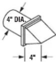
- Use only rigid metal or flexible metal 4-in. diameter ductwork for exhausting to the outdoors. Never use plastic or other combustible, easy-to-puncture ductwork.
- This appliance must be properly grounded and installed as described in these instructions.
- Do not install or store appliance in an area where it will be exposed to water and/or weather
- Install the dryer where the temperature is above 50^ for satisfactory operation of the dryer control system.
NOTE: Installation and service of this dryer requires basic mechanical and electrical skills. It is your responsibility to contact a qualified installer to make the electrical connections.
TOOLS YOU WILL NEED

SLIP JOINT PLIERS
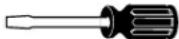
FLAT BLADE SCREWDRIVER
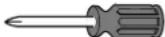
PHILLIPS SCREWDRIVER
MATERIALS YOU WILL NEED
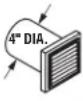
4" DIA. METAL DUCT (RECOMMENDED)

4" DUCT CLAMPS (2) OR
4" SPRING CLAMPS (2)

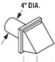
4" DIA. METAL ELBOW

EXHAUST HOOD
SAFETY GLASSES

4" DIA. FLEXIBLE METAL DUCT (IF NEEDED)

DUCT TAPE
GLOVES

3/4" STRAIN RELIEF UL RECOGNIZED

DRYER POWER CORD KIT (NOT PROVIDED WITH DRYER)
UL RATED 120/240V, 30A WITH 3 OR 4 PRONGS. IDENTIFY THE PLUG TYPE AS PER THE HOUSE RECEPTACLE BEFORE PURCHASING LINE CORD.
Step 1 Prepare the Area and Exhaust for Installation of New Dryer (see section 1).
Step 2 Check and Ensure the Existing External Exhaust is Clean (see section 1) and Meets Attached Installation Specifications (see section 3).
Step 3 Remove the Foam Shipping Pads (see section 1).
Step 4 Move the Dryer to the Desired Location.
Step 5 Connect the Power Supply (see section 2).
Step 6 Connect the External Exhaust (see section 4).
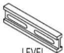
Step 7 Level Your Dryer (see section 5).
Step 8 Check the Operation of the Power Supply and Venting.
Step 9 Place the Owners Manual and the Installation Instructions in a Location Where They Will Be Noticed By the Owner.
For Alcove or Closet Installation, see section 6. For Bathroom or Bedroom Installation, see section 7. For Mobile or Manufactured Home see, section 8. For side or bottom exhaust, see section 9.
Installation Instructions
Minimum Clearance Other Than Alcove or Closet Installation
Minimum clearance to combustible surfaces and for air opening are: 0 in. clearance both sides and 1 in. rear. Consideration must be given to provide adequate clearance for installation and service.
1 PREPARING FOR INSTALLATION OF NEW DRYER

TIP: Install your dryer before installing your washer. This will allow better access when installing dryer exhaust.
REMOVING LINT FROM WALL EXHAUST OPENING
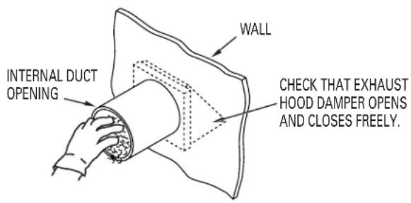
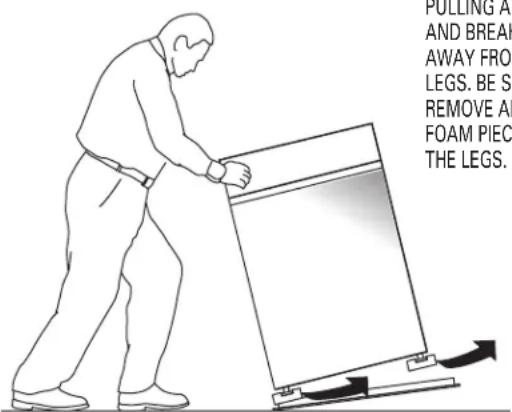
TILT THE DRYER SIDEWAYS AND REMOVE THE FOAM SHIPPING PADS BY PULLING AT THE SIDES AND BREAKING THEM AWAY FROM THE DRYER LEGS. BE SURE TO REMOVE ALL OF THE FOAM PIECES AROUND THE LEGS.
② ELECTRICAL CONNECTION INFORMATION
⚠ WARNING - TO REDUCE THE RISK OF FIRE, ELECTRICAL SHOCK AND PERSONAL INJURY:
- DO NOT USE AN EXTENSION CORD OR AN ADAPTER PLUG WITH THIS APPLIANCE.
Dryer must be electrically grounded in accordance with local codes and ordinances, or in the absence of local codes, in accordance with the NATIONAL ELECTRICAL CODE, ANSI/NFPA NO. 70.
ELECTRICAL REQUIREMENTS
This dryer must be connected to an individual branch circuit, protected by the required time-delay fuses or circuit breakers. A four or three-wire, single phase, 120/240V or 120/208V, 60Hz, 30 amp circuit is required.
If the electric supply does not meet the above specifications, then call a licensed electrician.
GROUNDING INSTRUCTIONS
This dryer must be connected to a grounded metal, permanent wiring system, or an equipment-grounding conductor must be run with the circuit conductors and connected to the equipment-grounding terminal on the appliance.
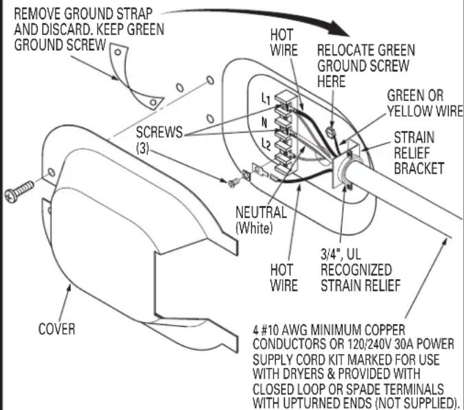
CONNECTING DRYER USING 4-WIRE CONNECTION (MUST BE USED FOR MOBILE HOME INSTALLATION)
NOTE: Since January 1, 1996, the National Electric Code requires that new constructions utilize a 4 wire connection to an electric dryer.
Installation Instructions
- Turn off the circuit breaker (s) (30 amp) or remove the dryer's circuit fuse at the electrical box.
- Be sure the dryer cord is unplugged from the wall receptacle.
- Remove the power cord cover located at the lower back.
- Remove and discard ground strap. Keep the green ground screw for step 7.
- Install 3/4 in. UL recognized strain relief to power cord entry hole. Bring power cord through strain relief.
- Connect power cord as follows:
A. Connect the 2 hot lines to the outer screws of the terminal block (marked L1 and L2).
B. Connect the neutral (white) line to the center of the terminal block (marked N).
- Attach ground wire of power cord with the green ground screw (hole above strain relief bracket). Tighten all terminal block screws (3) completely.
- Properly secure power cord to strain relief.
- Reinstall the cover.

WARNING: NEVER LEAVE THE
COVER OFF OF THE TERMINAL BLOCK.
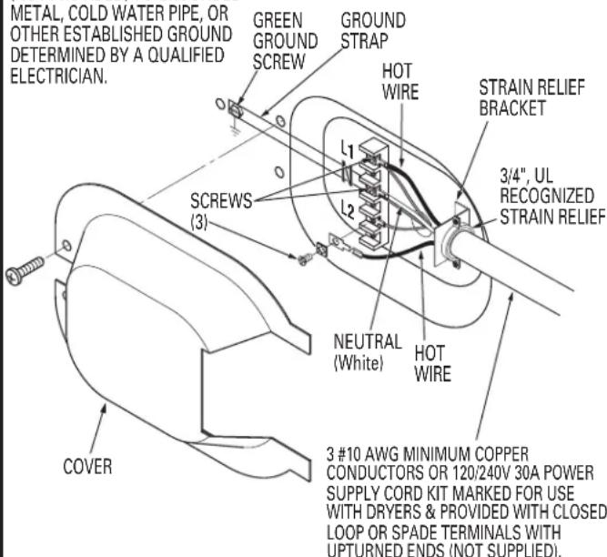
CONNECTING DRYER USING 3-WIRE CONNECTION
IF REQUIRED, BY LOCAL CODE, INSTALL EXTERNAL GROUND (NOT PROVIDED) TO GROUNDED METAL, COLD WATER PIPE, OR OTHER ESTABLISHED GROUND DETERMINED BY A QUALIFIED ELECTRICIAN.
- Turn off the circuit breaker (s) (30 amp) or remove the dryer's circuit fuse at the electrical box.
- Be sure the dryer cord is unplugged from the wall.
- Remove the power cord cover located at the lower back.
- Install 3/4 in. UL recognized strain relief to power cord entry hole. Bring power cord through strain relief.
- Connect power cord as follows:
A. Connect the 2 hot lines to the outer screws of the terminal block (marked L1 and L2).
B. Connect the neutral (white) line to the center of terminal block (marked N).
- Be sure ground strap is connected to neutral (center) terminal of block and to green ground screw on cabinet rear. Tighten all terminal block screws (3) completely.
- Properly secure power cord to strain relief.
- Reinstall the cover.

WARNING: NEVER LEAVE THE
COVER OFF OF THE TERMINAL BLOCK.

EXHAUST INFORMATION

WARNING - USE ONLY METAL 4-IN. DUCT. NOT USE DUCT LONGER THAN SPECIFIED THE EXHAUST LENGTH TABLE.
Using exhaust longer than specified length will:
- Increase the drying times and the energy cost.
- Reduce the dryer life.
- Accumulate lint, creating a potential fire hazard.
The correct exhaust installation is YOUR RESPONSIBILITY Problems due to incorrect installation are not covered by the warranty.
The MAXIMUM ALLOWABLE length of the exhaust system depends upon the type of duct, number of turns, the type of exhaust hood (wall cap), and all conditions noted below. Both rigid and flexible metal duct are shown in the table below.
EXHAUST LENGTH
| RECOMMENDED MAXIMUM LENGTH | ||||
| Exhaust Hood Types | ||||
| Recommended | Use only for short run installations | |||
 |  |  | ||
| 2-1/2" | ||||
| No. of 902 Elbows | Rigid Metal | Flexible Metal | Rigid Metal | Flexible Metal |
| 0 | 150 Feet | 55 Feet | 125 Feet | 45 Feet |
| 1 | 135 Feet | 52 Feet | 115 Feet | 42 Feet |
| 2 | 125 Feet | 49 Feet | 105 Feet | 39 Feet |
| 3 | 115 Feet | 46 Feet | 95 Feet | 36 Feet |
| 4 | 105 Feet | 43 Feet | 85 Feet | 33 Feet |
| 5 | 95 Feet | 40 Feet | 75 Feet | 30 Feet |
If using flexible metal duct, please refer to page 5.
EXHAUST SYSTEM CHECK LIST
HOOD OR WALL CAP
- Terminate in a manner to prevent back drafts or entry of birds or other wildlife.
- Termination should present minimal resistance to the exhaust air flow and should require little or no maintenance to prevent clogging.
- Never install a screen in or over the exhaust duct. This could cause lint build up.
- Wall caps must be installed at least 12 in. above ground level or any other obstruction with the opening pointed down.
- If roof vents or louvered plenums are used, they must be equivalent to a 4-in. dampened wall cap in regard to resistance to air flow, prevention of back drafts, and maintenance required to prevent clogging.
SEPARATION OF TURNS
For best performance, separate all turns by at least 4 ft. of straight duct, including distance between last turn and exhaust hood.
TURNS OTHER THAN 90°
• One turn of 45^ or less may be ignored.
- Two 45^ turns should be treated as one 90^ turn.
• Each turn over 45^ should be treated as one 90^ turn.
SEALING OF JOINTS
- All joints should be tight to avoid leaks. The male end of each section of duct must point away from the dryer.
- Do not assemble the ductwork with fasteners that extend into the duct. They will serve as a collection point for lint.
- Duct joints can be made air and moisture-tight by wrapping the overlapped joints with duct tape.
• Horizontal runs should slope down toward the outdoors 1/2 inch per foot
INSULATION
Duct work that runs through an unheated area or is near air conditioning should be insulated to reduce condensation and lint build-up.
Installation Instructions
4 EXHAUST CONNECTION

WARNING - TO REDUCE THE RISK FIRE OR PERSONAL INJURY:
- Exhausting the dryer to the outdoors is strongly recommended to prevent large amounts of moisture from being blown into the room.
- Use only metal duct.
- Do not terminate exhaust in a chimney, any gas vent, under an enclosed floor (crawl space), or into an attic. The accumulated lint could create a fire hazard.
- Provide an access for inspection and cleaning of the exhaust system, especially at turns. Inspect and clean at least once a year.
- Never terminate the exhaust into a common duct with a kitchen exhaust. A combination of lint and grease could create a fire hazard.
- Do not obstruct incoming or exhausted air.
THIS DRYER COMES READY FOR REAR EXHAUSTING. IF SPACE IS LIMITED, USE THE INSTRUCTIONS IN SECTION 9 TO EXHAUST DIRECTLY FROM THE SIDES OR BOTTOM OF THE CABINET.
STANDARD REAR EXHAUST
(Vented at floor level)

NOTE: WE STRONGLY RECOMMEND SOLID METAL EXHAUST DUCTING. HOWEVER, IF FLEXIBLE DUCTING IS USED IT MUST BE METAL NOT PLASTIC.
STANDARD REAR EXHAUST
(Vented above floor level)
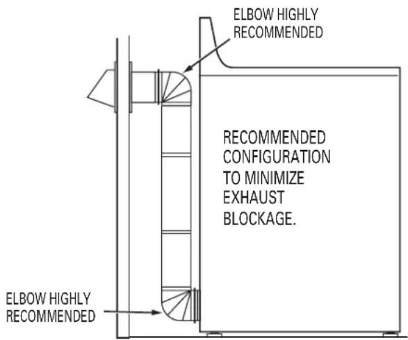
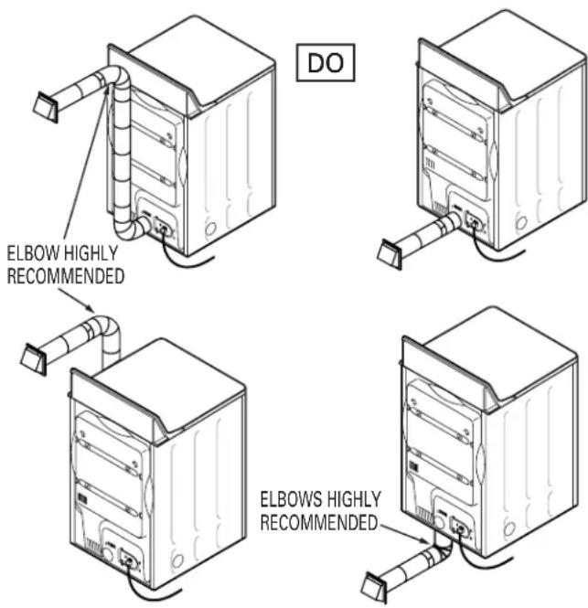
NOTE: ELBOWS WILL PREVENT DUCT KINKING AND COLLAPSING.
⑤ LEVELING AND STABILIZING YOUR DRYER
Installation Instructions, Indoor Exhausting
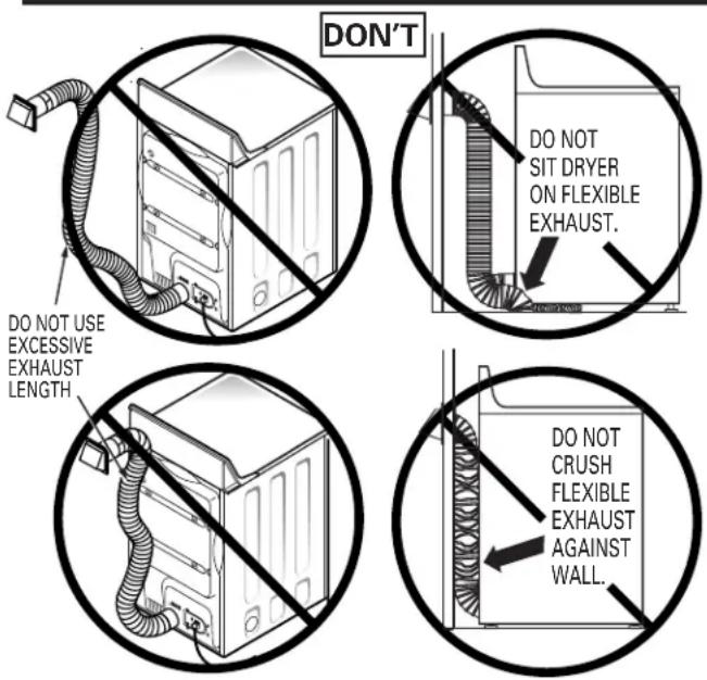
USING FLEXIBLE METAL DUCTS
If rigid all-metal duct cannot be used, then flexible all-metal ducting can be used, but it will reduce the maximum recommended duct length. In special installations when it is impossible to use only metal ducting, then UL-listed clothes dryer flexible metal transition duct may be used as transition venting between the dryer and wall connection only. The use of this ducting will affect dry time.
If flexible transition duct is necessary, the following directions must be followed.
- Use the Shortest Length Possible.
- Stretch the Duct to Its Maximum Length to avoid kinks.
- Do Not Crush or Collapse the Duct.
- Never Use Transition Duct Inside the Wall or Inside the Dryer.
- Avoid Resting the Duct on Sharp Objects.
- Venting Must Conform to Local Building Codes.
INDOOR EXHAUSTING
NOTE: MOBILE HOME, BEDROOM, BATHROOM, ALCOVE OR CLOSET INSTALLATIONS MUST BE EXHAUSTED TO THE OUTDOORS
OTHER INSTALLATIONS: If the installation makes it impossible to exhaust to the outdoors, a 4" exhaust deflector (WE25X278) must be installed. A clearance of 8" is required between the rear of the dryer and the wall, and the deflector should be pointing up.
NOTE: EXHAUSTING TO THE OUTDOORS IS STRONGLY RECOMMENDED, EXHAUSTING INDOORS MAY CAUSE LINT ACCUMULATION, AND MOISTURE DAMAGE INCLUDING MOLD AND MILDEW.
⑥ ALCOVE OR CLOSET INSTALLATION
- If your dryer is approved for installation in an alcove or closet, it will be stated on a label on the dryer back.
- The dryer MUST be vented to the outdoors. See the EXHAUST INFORMATION sections 3 & 4.
- Minimum clearance between dryer cabinet and adjacent walls or other surfaces is:
0 in. either side
3 in. front and rear - Minimum vertical space from floor to overhead cabinets, ceiling, etc. is 52 in.
- Closet doors must be louvered or otherwise ventilated and must contain a minimum of 60 sq. in. of open area equally distributed. If the closet contains both a washer and a dryer, doors must contain a minimum of 120 sq. in. of open area equally distributed.
7 BATHROOM OR BEDROOM INSTALLATION
- The dryer MUST be vented to the outdoors. See EXHAUST INFORMATION section 3 & 4.
- The installation must conform with local codes or, in the absence of local codes, with the NATIONAL ELECTRICAL CODE, ANSI/NFPA NO. 70.
8 MOBILE OR MANUFACTURED HOME INSTALLATION
- Installation must conform to the MANUFACTURED HOME CONSTRUCTION & SAFETY STANDARD, TITLE 24, PART 32-80 or, when such standard is not applicable, with AMERICAN NATIONAL STANDARD FOR MOBILE HOME, ANSI/NFPA NO. 501B.
- The dryer MUST be vented to the outdoors with the termination securely fastened to the mobile home structure. (See EXHAUST INFORMATION section 3 & 4.)
- The vent MUST NOT be terminated beneath a mobile or manufactured home.
• The vent duct material MUST BE METAL. - Do not use sheet metal screws or other fastening devices which extend into the interior of the exhaust vent.
• See section 2 for electrical connection information.
Installation Instructions:
⑨ DRYER EXHAUST TO RIGHT OR BOTTOM CABINET
WARNING - BEFORE PERFORMING THIS EXHAUST INSTALLATION, BE SURE TO DISCONNECT THE DRYER FROM ITS ELECTRICAL SUPPLY. PROTECT YOUR HANDS AND AR MS FROM SHARP EDGES WHEN WORKING INSIDE THE CABINET. BE SURE TO WEAR GLOVES

Detach and remove the bottom, right or left side knockout as desired. Remove the screw inside the dryer exhaust duct and save. Pull the duct out of the dryer.
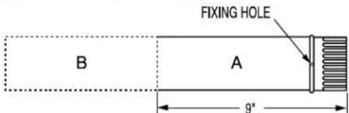
Cut the duct as shown and keep portion A.
TAB LOCATION
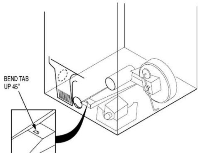
Through the rear opening, locate the tab in the middle of the appliance base. Lift the tab to about 45^ using a flat blade screwdriver
ADDING NEW DUCT
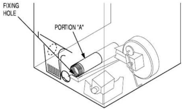
Reconnect the cut portion (A) of the duct to the blower housing. Make sure that the shortened duct is aligned with the tab in the base. Use the screw saved previously to secure the duct in place through the tab on the appliance base.
ADDING ELBOW AND DUCT FOR EXHAUST TO RIGHT SIDE OF CABINET
- Preassemble 4" elbow with 4" duct. Wrap duct tape around joint. - Insert duct assembly, elbow first, through the side opening and connect the elbow to the dryer internal duct.
CAUTION: Be sure not to pull or damage the electrical wires inside the dryer when inserting the duct.
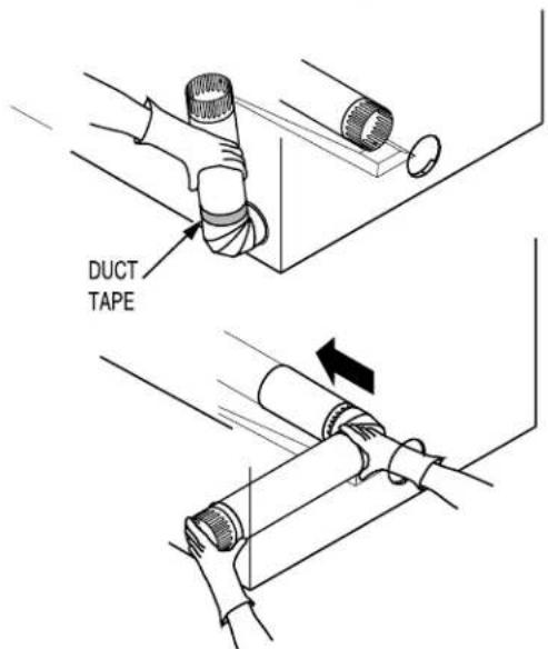
- Apply duct tape as shown on the joint between the dryer internal duct and the elbow.
CAUTION:
Internal duct joints must be secured with tape, otherwise they may separate and cause a safety hazard.
Installation Instructions
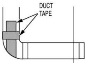
ADDING ELBOW FOR EXHAUST THROUGH BOTTOM OF CABINET
- Insert the elbow through the rear opening and connect it to the dryer internal duct.
- Apply duct tape on the joint between the dryer internal duct and elbow, as shown on page 6.

natural_image
Line drawing of a hand gripping a cylindrical object, no text or symbols presentCAUTION: Internal duct joints must be secured with tape, otherwise they may separate and cause a safety hazard.
ADDING COVER PLATE TO REAR OF CABINET (SIDES AND BOTTOM EXHAUST)
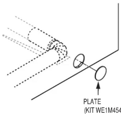
Connect standard metal elbows and ducts to complete the exhaust system. Cover back opening with a plate (Kit WE1M454) available from your local service provider. Place dryer in final location.
⚠ WARNING - NEVER LEAVE THE BACK OPENING WITHOUT THE PLATE. (Kit WE1M454)
TO REGISTER YOUR DRYER
CALL TOLL-FREE
1-888-269-1192
Prompt registration confirms your right to protection under the terms of your warranty.
www.GEAppliances.com (US)
For Questions on Installation, Call: 1-800-626-2003 (US)
500A187P049
2-01 ON
Pub. #31-16109
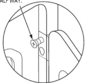
10 CHANGING DIRECTION OF DOOR OPENING
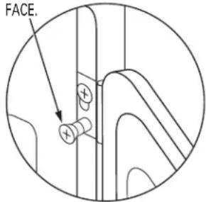
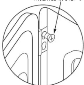
- Open the door and remove the filler plugs opposite the hinges. With the door completely open, remove the bottom screws from each hinge on the dryer face. Insert these screws about half way into the TOP holes, for each hinge on the opposite side (where you removed the filler plugs). Apply firm pressure to get the screw started.
- Loosen the top screws from each hinge on the dryer face half way. With one hand holding the top of the door and the other hand holding the bottom, remove the door from the dryer by lifting it UP and OUT.
- Rotate the door 180°. Insert the door on the opposite side of the opening by moving the door IN and DOWN until the top hinge and the bottom hinge are resting on the top screws inserted in step 1.
- Remove the remaining screws from the side of the opening from which the door was removed. With these screws secure each hinge at the bottom. Tighten the two top screws on each hinge. Reinsert the plastic plugs on the side from which the door was removed.
REMOVE THE
BOTTOM SCREW
FROM EACH HINGE
ON THE DRYER
FACE.
LOOSEN THE TOP
SCREWS FROM
EACH HINGE ON
THE DRYER FACE
HALF WAY.
MOVE THE DOOR IN AND
DOWN UNTIL THE TOP HINGE AND THE BOTTOM HINGE ARE RESTING ON THE TOP SCREW INSERTED IN STEP 1.
SECURE EACH HINGE
AT THE BOTTOM AND
TIGHTEN THE TWO TOP
SCREWS OF EACH HINGE.
natural_image
Technical line drawing of a mechanical component with an arrow pointing to a circular feature (no text or symbols)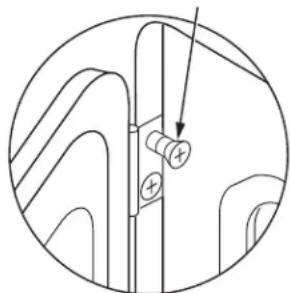
natural_image
Pure mechanical diagram showing a bolt and nut assembly without any text, numbers, or symbols11 SERVICING
⚠ WARNING - LABEL ALL WIRES PRIOR TO DISCONNECTING WHEN SERVICING CONTROLS. WIRING ERRORS CAN CAUSE IMPROPER AND DANGEROUS OPERATION AFTER SERVICING/INSTALLATION.
For servicing phone numbers for replacement parts, and other information, refer to Owner's Manual or visit our Web site.
Notes


- Installation Instructions
- Electric Dryer 49
- BEFORE YOU BEGIN
- FOR YOUR SAFETY:
- WARNING
- TOOLS YOU WILL NEED
- MATERIALS YOU WILL NEED
- Minimum Clearance Other Than Alcove or Closet Installation
- ② ELECTRICAL CONNECTION INFORMATION
- ELECTRICAL REQUIREMENTS
- GROUNDING INSTRUCTIONS
- CONNECTING DRYER USING 4-WIRE CONNECTION (MUST BE USED FOR MOBILE HOME INSTALLATION)
- WARNING: NEVER LEAVE THE
- COVER OFF OF THE TERMINAL BLOCK.
- CONNECTING DRYER USING 3-WIRE CONNECTION
- EXHAUST INFORMATION
- WARNING - USE ONLY METAL 4-IN. DUCT. NOT USE DUCT LONGER THAN SPECIFIED THE EXHAUST LENGTH TABLE.
- EXHAUST SYSTEM CHECK LIST
- HOOD OR WALL CAP
- SEPARATION OF TURNS
- TURNS OTHER THAN 90°
- SEALING OF JOINTS
- INSULATION
- EXHAUST CONNECTION
- WARNING - TO REDUCE THE RISK FIRE OR PERSONAL INJURY:
- THIS DRYER COMES READY FOR REAR EXHAUSTING. IF SPACE IS LIMITED, USE THE INSTRUCTIONS IN SECTION 9 TO EXHAUST DIRECTLY FROM THE SIDES OR BOTTOM OF THE CABINET.
- ⑤ LEVELING AND STABILIZING YOUR DRYER
- Installation Instructions, Indoor Exhausting
- USING FLEXIBLE METAL DUCTS
- INDOOR EXHAUSTING
- NOTE: MOBILE HOME, BEDROOM, BATHROOM, ALCOVE OR CLOSET INSTALLATIONS MUST BE EXHAUSTED TO THE OUTDOORS
- NOTE: EXHAUSTING TO THE OUTDOORS IS STRONGLY RECOMMENDED, EXHAUSTING INDOORS MAY CAUSE LINT ACCUMULATION, AND MOISTURE DAMAGE INCLUDING MOLD AND MILDEW.
- ⑥ ALCOVE OR CLOSET INSTALLATION
- BATHROOM OR BEDROOM INSTALLATION
- MOBILE OR MANUFACTURED HOME INSTALLATION
- Installation Instructions:
- ⑨ DRYER EXHAUST TO RIGHT OR BOTTOM CABINET
- ADDING ELBOW AND DUCT FOR EXHAUST TO RIGHT SIDE OF CABINET
- CAUTION:
- ADDING ELBOW FOR EXHAUST THROUGH BOTTOM OF CABINET
- ⚠ WARNING - NEVER LEAVE THE BACK OPENING WITHOUT THE PLATE. (Kit WE1M454)
- CHANGING DIRECTION OF DOOR OPENING
- SERVICING
- Notes
Brand : GE
Model : Profile DPR483EAWW
Category : Coffee maker