
HIC-B3CGAFH - Hot plate HAIER - Free user manual and instructions
Find the device manual for free HIC-B3CGAFH HAIER in PDF.


| Product type | Built-in gas hob |
| Model | HIC-B3CGAFH |
| Brand | Haier |
| Gas pressure | 2800 Pa |
| Dimensions (W x D x H) | 940 x 460 x 92 mm |
| Cutout dimensions (W x D) | 830 x 400 mm |
| Net weight | 18.5 kg |
| Rated voltage | DC 3V |
| Total heat input | 12.1 kW (881 g/h) |
| Number of burners | 3 |
| Left burner power (ultra rapid) | 5.10 kW (brass outer + inner) |
| Middle burner power (auxiliary) | 1.90 kW (single burner) |
| Right burner power (ultra rapid) | 5.10 kW (brass outer + inner) |
| Burner material | Brass |
| Anti-drying guard function | Yes (left burner only, temperature sensor up to 298°C) |
| Low battery indication | Yes (alarm for 10 seconds) |
| Hood-Hob connectivity | Yes (wireless, compatible with Haier range hoods) |
| Safety valve | Yes (flame failure device) |
| Gas connection | Rubber hose or rigid pipe |
| Cleaning | Use soft cloth and mild detergent; avoid abrasive substances |
| Warranty | 1 year comprehensive (parts and labour), plus 1 year on glass, plus 4 years on burner and valve |
| Repairability | Authorized service only; replaceable burners, taps, and electronic components |
| Power supply for ignition | 2 x R20 batteries (zinc-manganese) |
Frequently Asked Questions - HIC-B3CGAFH HAIER
User questions about HIC-B3CGAFH HAIER
0 question about this device. Answer the ones you know or ask your own.
Ask a new question about this device
Download the instructions for your Hot plate in PDF format for free! Find your manual HIC-B3CGAFH - HAIER and take your electronic device back in hand. On this page are published all the documents necessary for the use of your device. HIC-B3CGAFH by HAIER.
USER MANUAL HIC-B3CGAFH HAIER
INSTALLATION GUIDE/USER GUIDE
CONTENTS
INTRODUCTION 1
SAFETY AND WARNING 2
1 FEATURES AND TECHNICAL DATA 6
2.HOW TO USE THE COOKTOP 9
--GAS BURNERS 9
--INSTALLING THE BATTERY 10
--LIGHTING THE BURNERS 10
--ADJUSTING THE AIR EJECTION 11
--OPERATING OF THE ANTI DRYING GUARD FUNCTION 12
--CHOICE OF THE BURNER 13
--THE USE OF THE HOOD-HOB CONNECTIVITY 14
3.CLEANING AND MAINTENANCE 15
4.INSTALLATION 18
5.GAS SECTION 21
6.WARRANTY 25
Dear Customer,
Thank you for having purchased and given your preference to our product.
The safety precautions and recommendations reported below are for your own safety and that of others. They will also provide a means by which to make full use of the features offered by your appliance.
Please preserve this booklet carefully. It may be useful in future, either to yourself or to others in the event that doubts should arise relating to its operation.
This appliance must be used only for the task it has explicitly been designed for, that is for cooking foodstuffs. Any other form of usage is to be considered as inappropriate and therefore dangerous.
The manufacturer declines all responsibility in the event of damage caused by improper, incorrect or illogical use of the appliance.
IMPORTANT SAFETY PRECAUTIONS AND RECOMMENDATIONS
IMPORTANT: This appliance is designed and manufactured solely for the cooking of domestic (household) food and is not suitable for any non domestic application and therefore should not be used in a commercial environment.
The appliance guarantee will be void if the appliance is used within a non domestic environment i.e. a semi commercial, commercial or communal environment.
Read the instructions carefully before installing and using the appliance.
- This appliance has been designed and manufactured in compliance with the applicable standards for the household cooking products, including those for surface temperatures.
Some people with sensitive skin may have a more pronounced temperature perception with some components although these parts are within the limits allowed by the norms.
The complete safety of the appliance also depends on the correct use, we therefore recommend to always pay a extreme attention while using the product, especially in the presence of children. - After having unpacked the appliance, check to ensure that it is not damaged.
In case of doubt, do not use it and consult your supplier or a professionally qualified technician. - Packing elements (i.e. plastic bags, polystyrene foam, nails, packing straps, etc.) should not be left around within easy reach of children, as these may cause serious injuries.
- Some appliances are supplied with a protective film on steel and aluminium parts. This film must be removed before using the appliance.
- IMPORTANT: The use of suitable protective clothing/gloves is recommended when handling or cleaning this appliance.
- Do not attempt to modify the technical characteristics of the appliance as this may become dangerous to use. The manufacturer declines all responsibility for any inconvenience resulting from the inobservance of this condition.
- CAUTION: this appliance must only be installed in a permanently ventilated room in compliance with the applicable regulations.
- Do not carry out cleaning or maintenance operations on the appliance without having previously disconnected it from the electric power supply.
- Do not use a steam cleaner because the moisture can get into the appliance therefore making it unsafe.
- Do not touch the appliance with wet or damp hands (or feet).
- Do not use the appliance whilst in bare feet.
- If you should decide not to use this appliance any longer (or decide to substitute another model), before disposing of it, it is recommended that it be made inoperative in an appropriate manner in accordance to health and environmental protection regulations, ensuring in particular that all potentially hazardous parts be made harmless, especially in relation to children who could play with unused appliances.
- The various components of the appliance are recyclable. Dispose of them in accordance with the regulations in force in your country. If the appliance is to be scrapped, remove the power cord.
• After use, ensure that the knobs are in the off position.
- Children less than 8 years of age shall be kept away unless continuously supervised.
- This appliance can be used by children aged from 8 years and above and persons with reduced physical, sensory or mental capabilities or lack of experience and knowledge if they have been given supervision or instruction concerning use of the appliance in a safe way and understand the hazards involved. Children shall not play with the appliance. Cleaning and user maintenance shall not be made by children without supervision.
- The manufacturer declines all liability for injury to persons or damage to property caused by incorrect or improper use of the appliance.
- WARNING: During use the appliance and its accessible parts become hot; they remain hot for some time after use.
- Care should be taken to avoid touching heating elements on the hob.
- To avoid burns and scalds, young children should be kept away.
- WARNING: Unattended cooking on a hob with fat or oil can be dangerous and may result in fire. NEVER try to extinguish a fire with water, but switch off the appliance and then cover flame e.g. with a lid or a fire blanket.
- WARNING: Danger of fire: do not store items on the cooking surfaces.
- WARNING: When correctly installed, your product meets all safety requirements laid down for this type of product category. However special care should be taken around the underneath of the appliance as this area is not designed or intended to be touched and may contain sharp or rough edges, that may cause injury.
- CAUTION: The cooking process has to be supervised. A short term cooking process has to be supervised continuously.
- If the power supply cable is damaged, it must be replaced only by an authorized service agent in order to avoid a hazard.
- This appliance is not connected to a combustion products evacuation device. It shall be installed and connected in accordance with current installation regulations. Particular attention shall be given to the relevant requirements regarding ventilation.
- Warning the user against the use of cooking vessels on the hotplate that overlap its edges.
Model:HIC-B3CGAFH


Fig. 1.1
| Model HIC-B3CGAFH Gas Pressure 2800 Pa | |||
| Unit Dimensions(mm) 940x460x92 Gas category I3B/P(30) | |||
| Installed Dimensions(mm) 830x400 Rated Voltage DC 3V | |||
| Net Weight | 18.5kg | Total Heat Input | 12.1kW(881g/h) |
| Normal Heat Input | Left: 5.1kW Mid:1.9kW Right: 5.1kW | ||
GAS BURNERS
- Left (Ultra Rapid) 5,10 kW Inner Brass Burner +Outer Brass Burner
- Middle(Auxiliary) 1,90 kW Single Burner
- 5,10 kW Right(Ultra Rapid) Burner +Outer Brass Burner
CONTROLS DESCRIPTION
- Burner control knob (1.Left burner)
- Burner control knob (2.Middle burner)
- Burner control knob (3.Right burner)
- Temperature Sensor (*), Only Left Burner has
- Inner Brass Burner
- outer Brass Burner
NOTES (\*): ANTI DRYING GUARD FUNCTION (OVERHEATING PROTECTION FUNCTION)
■ ANTI DRYING GUARD FUNCTION (Only the left burner has the function)
During process of cooking, in case water or food inside cooking pot or pan is dried out, and the bottom temperature of pot or pan will raise dramatically, and the ANTI DRY device will start working to cut off gas supply once the temperature reaches 298^ C (according to lab test data, the sensor start up range is between 290^ C\~ 320^ C on basis of different pots or pans). At the same time, the buzzer alarm will also starting working for 20 seconds.
IMPORTANT: Please place pot or pan at right position to ensure the pot or pan bottom are in proper touch with the sensor, or else the ANTI DRYING GUARD function may not work properly. The ANTI DRYING GUARD function will start working within a few minutes after the water is thoroughly dried out, and gas supply can not be cut immediately.
IMPORTANT: In case the left burner keeps burning without any pan above it for around 3 minutes (according to the laboratory test data), then the ANTI DRYING GUARD device will start working and will cut off gas supply, then buzzer Alarm will start working for about 20 seconds.
IMPORTANT: In case ANTI DRYING GUARD function starts up, the left burner can not be reignited until the sensor temperature drop to normal level. Anyway, if user takes away the dried out pot or pan, then it will take less time to reignite the left burner.
■ LOW BATTERY INDICATION FUCTION
When the battery voltage is too low to start up the ANTI DRYING GUARD, then the hob will alarm for around 10 seconds to indicate user to change the battery. In this case the left burner can not work properly, but other burners without ANTI DRYING GUARD can work as usual.
IMPORTANT: After using of the gas hob or after starting up of the ANTI DRYING GUARD, please turn the knob to the off position to expand battery life. Otherwise, the ANTI DRYING GUARD sensor will be always working on standby detection status and battery power will be consumed continuously; When ANTI DRYING GUARD is on, do not try to ignite the burners before the buzz alarm is off.
NOTES:
■ The electric ignition is incorporated in the knobs.
■ The appliance has a safety valve system fitted, the flow of gas will be stopped if and when the flame should accidentally go out.
CAUTION:
If the burner is accidentally extinguished, turn the gas off at the control knob and wait at least 1 minute before attempting to relight.
CAUTION:
Gas hobs produce heat and humidity in the environment in which they are installed. Ensure that the cooking area is well ventilated by opening the natural ventilation grilles or by installing an extractor hood connected to an outlet duct.
CAUTION:
If the hob is used for a prolonged time it may be necessary to provide further ventilation by opening a window or by increasing the suction power of the extractor hood (if fitted).
GAS BURNERS
Gas flow to the burners is adjusted by turning the knobs (illustrated in fig. 2.1) which control the safety valves.
Turning the knob, so that the indicator line points to the symbols printed on the panel, achieves the following functions:
![- symbol ● closed valve - symbol [icon] maximum aperture or flow - symbol ○ minimum aperture or flow](/content/2026/06/1206401/images/66e420800265874820dd6885b7e65454f087370c323cf4e83ef121f4a65eda8d.jpg)
■ The maximum aperture position permits rapid boiling of liquids, whereas the minimum aperture position allows slower warming of food or maintaining boiling conditions of liquids.
■ To reduce the gas flow to minimum rotate the knob further anti-clockwise to point the indicator towards the small flame symbol
■ Other intermediate operating adjustments can be achieved by positioning the indicator between the maximum and minimum aperture positions, and never between the maximum aperture and closed positions.
IMPORTANT: To turn the control knob from the closed position “●” to the maximum aperture position “💡”, first press in the knob and then turn it anti-clockwise.
N.B. When the hob is not being used, set the gas knobs to their closed positions and also close the cock valve on the gas bottle or the main gas supply line.

natural_image
Diagram of a circular object with concentric rings and two small symbols, labeled Fig. 2.1 (no text or numbers on the diagram itself)Caution!
Do not cover the hob with aluminium foils.
Caution!
The cooking hob becomes very hot during operation.
Keep children well out of reach.
INSTALLING THE BATTERY
Firstly, install two pcs of Standard R20 batteries (Common zinc-manganese battery, IEC mark R20) in the battery box at the bottom of the gas hob, and then perform the ignition and fire size adjustment according to the order of illustration. (illustrated in fig. 2.3)

To ignite the burner, the following instructions are to be followed:
- Press in the corresponding knob and turn counter-clockwise (fig. 2.3) to the full flame position marked by the “💡” symbol (fig. 2.1); hold the knob in until the flame has been lit.
In the case of a mains failure light the burner with a match or lighted taper.
-
Wait for a few seconds after the gas burner has been lit before letting go of the knob (valve activation delay).
-
Adjust the gas valve to the desired position.

natural_image
Diagram of a mechanical component with a downward arrow and curved arrow indicating rotation (no text or symbols)If the burner flame should go out for some reason, the safety valve will automatically stop the gas flow.
To re-light the burner, return the knob to the closed "●" position, wait for at least 1 minute and then repeat the lighting procedure.
Note: If your local gas supply makes it difficult to light the burner with the knob set to maximum, set the knob to minimum and repeat the operation.

IMPORTANT:T After using the burner check the control knobs are in the closed “●” position.
ADJUSTING THE AIR EJECTION
☐ When the flame is in poor condition, adjust the handle at the bottom of the hob to increase or reduce air amount(illustrated in fig. 2.4, fig. 2.5 and fig. 2.6), in order to combust completely.
☐ When the flame is long and yellow(incompletele combustion flame), turn clockwise to adjust the handle to increase the amount of air intake according to the position shown in the picture.
☐ When the flame is lifting out of the fire hole, turn anti-clockwise to adjust the handle to reduce the amount of air intake according to the position shown in the picture.
☐ When the flame reaches the normal combustion state, put salient point of the handle into the fixed hole.
a) Normal flame

Increasing the amount of air when turning the handle anti-clockwise Reducing the amount of air when turning the handle clockwise
handle 1: Adjust the flame of outer brass burner(left burner and right burner)
handle 2: Adjust the flame of inner brass burner(left burner and right burner) or middle burner

a) shape: To ensure contact closely between the temperature sensor and the pan, the pan bottom must be flat, and the diameter is at least 100mm.
b) material: Due to different thermal conductivity of pot, the accuracy of sensor temperature detection can be affected. The ceramic, aluminum alloy and ceramic layer (mainly heat insulating layer) with poor thermal conductivity are not suitable for the burner.
Applicable pan Inapplicable pan

pan
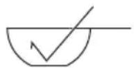
sauce pan
Fig. 2.7 Fig. 2.8

Apex pan
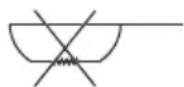
Bottom-concave pan

Ceramic or casserole pan
NOTES:
□ when you use the left burner, please make sure that the dimension of pot's bottom is over 100mm and the pot is made of stainless steel or iron alloy.
☐ IF the knob is not in the maximum position of the left burner, it will delay to cut out the gas valve when the pan is under water heating dry up, because the radiation heat of the pan is reduced.
☐ There are many factors that affect the sensitivity and operation time for the hob, and these may cause the function fail to start, such as unevenness of the pan bottom; the gas pressure drops; etc.
☐ If you cook on the left burner, such as frying and quick frying, it will cause ANTI DRYING GUARD FUNCTION to start and cut off the gas valve. Therefore, these should be cooked on the right burner because of above cause.
After the hob alarms for the low power, please change two new batteries in time. If you don't change them, the hob can still ignite normally, but the ANTI DRYING GUARD FUNCTION can't work as normal due to the low power.
□ ANTI DRYING GUARD FUNCTION is not completely intelligent, please don't leave the gas hob too far to avoid to happen accidents when it is working.
☐ After ANTI DRYING GUARD FUNCTION is activated, the left burner could be used only when the temperature of the sensor reduced to normal status.
CHOICE OF THE BURNER
The suitable burner must be chosen according to the diameter and the capacity used.
As an indication, the burners and the pots must be used in the following way:
| DIAMETERS OF PANS WHICH MAY BE USED ON THE BURNERS | |
| BURNERS MINIMUM MAXIMUM | |
| Auxiliary(Middle in fig. 1.1) | 6 cm 16cm |
| Ultra Rapid(Left and right in fig. 1.1) | 18cm 32 cm |
| do not use pans with concave or convex bases | |
It is important that the diameter of the pot be suitable to the potentiality of the burner so as not to compromise the high output of the burners and therefore energy waste.
A small pot on a large burner does not give you a boiling point in a shorter amount of time since the capacity of heat absorption of a liquid mass depends on the volume and the surface of the pot.

natural_image
Line drawing of a cooking pot on a stove (no text or symbols)
natural_image
Line drawing of a cooking pot with stirrer and heating elements (no text or symbols)Fig. 2.9
The use of the “Hood-Hob Connectivity” function
"Hood-Hob Connectivity" function.(It needs to be matched up and work together with Haier Range Hood which also has the same "Hood-Hob Connectivity" function)
(1) Match-up: While the Range Hood is at standby state, long press a function button for 5 seconds, after a "ding dong" sound, the key start to blink for 15 seconds, within this 15 seconds, Rotate the Knob of the Hob, another "Ding dong sound" mean the match-up is done.
(2) Hood-Hob Connectivity: After the match up is done, rotate the knob of the Hob and start the fire, the Range Hood will start to work automatically; After turning off the knob of Hob, Range Hood will turn off automatically after 3 minutes.
(3) Disconnection: At the standby state, long press same function button for 5 seconds, after "ding dong" sound, the key quickly flashing for 3 seconds, meaning disconnection success.
Note: When the “Hood-Hob Connectivity” function is started, if touch the control panel and select other wind speed, the Range Hood would execute according to the latest instruction and change speed accordingly. Remember to turn off the Range Hood manually after usage because in this case, “Hood-Hob Connectivity” function will not be effective for the turn-off part.
GENERAL ADVICE
- Before you begin cleaning, you must ensure that the appliance is switched off and disconnected from the electrical power supply.
- Important: The use of suitable protective clothing/gloves is recommended when handling or cleaning of this appliance.
• Under no circumstances should any external covers be removed for servicing or maintenance except by suitable qualified personnel. - It is advisable to clean when the appliance is cold and especially when cleaning the enamelled parts.
- Be very careful that no water penetrates inside the appliance.
- Avoid leaving alkaline or acidic substances (lemon juice, vinegar, etc.) on the surfaces.
- Avoid using cleaning products with a chlorine or acidic base.
- Do not use a steam cleaner because the moisture can get into the appliance thus make it unsafe.
COOKING HOBS WITH
GLASS LID (optional)

natural_image
Prohibition sign showing crossed-out leaves and a diagonal line, no text presentDo not shut lid when burner alight.
ATTENTION
√ Do not lower the glass lid when the gas burner are still hot and when the oven, installed below the cooking hob, is on or still hot.
√ Do not lay on the glass lid hot pans and heavy kitchen utensils.
√ Dry off any liquid which may have spilt on the cover before opening it.
- Important: The manufacturer declines all liability for possible damage caused by the use of unsuitable products to clean the appliance.
WARNING! When correctly installed, your product meets all safety requirements laid down for this type of product category. However special care should be taken around the underneath of the appliance as this area is not designed or intended to be touched and may contain sharp or rough edges, that may cause injury.
ENAMELLED SURFACES
All the enamelled parts must be cleaned with a sponge and soapy water only or other non-abrasive products. Dry preferably with a microfibre or soft cloth.
If acid substances such as lemon juice, tomato conserve, vinegar etc. are left on the enamel for a long time they will etch it, making it opaque.
STAINLESS STEEL SURFACES
Stainless steel parts must be rinsed with water and dried with a soft and clean cloth.
For persistent dirt, use specific non-abrasive products available commercially or a little hot vinegar.
PAINTED PARTS AND SILKSCREEN PRINTED SURFACES
Clean using an appropriate product. Always dry thoroughly.
IMPORTANT: these parts must be cleaned very carefully to avoid scratching and abrasion. You are advised to use a soft cloth and neutral soap.
CAUTION: Do not use abrasive substances or non-neutral detergents as these will irreparably damage the surface.
GAS TAPS
• In the event of operating faults in the gas taps, call the Service Department.
BURNERS
• These parts can be removed and cleaned with appropriate products.
• After cleaning, the burners and their flame spreaders must be well dried and correctly replaced.
It's very important to do so can check that the burner flame spreader and the burenr (inner burner, outer burner, single burner) have been correctly positioned. Failure to do so can cause serious problems.
- Check that the electrode/s “G”(figs. 3.1) next to each burner is/are always clean to ensure trouble-free sparking.
- Check that the probe/s "P"(fig. 3.1) next to each burner is/are always clean to ensure correct operation of the safety valves.
Both the probe and ignition plug must be very carefully cleaned.
Note: To avoid damage to the electric ignition do not use it when the burners are not in place.

4 INSTALLATION
IMPORTANT :
- The appliance is designed and approved for domestic use only and should not be installed in a commercial, semi commercial or communal environment.
□Your product will not be guaranteed if installed in any of the above environments and could affect any third party or public liability insurances you may have. - This appliance is to be installed, regulated and adapted to function only by an authorized person in compliance with the current local regulations in force and in observation of the instructions supplied by the manufacturer.
□Failure to comply with this condition will render the guarantee invalid. - The appliance must be installed in compliance with regulations in force in your country and in observation of the manufacturer's instructions.
• Installation technicians must comply to current laws in force concerning ventilation and the evacuation of exhaust gases. - Incorrect installation, for which the manufacturer accepts no responsibility, may cause personal injury or damage.
- This appliance shall only be serviced by authorized personnel.
• Always disconnect the appliance from mains power supply before carrying out any maintenance operations or repairs. - Important: The use of suitable protective clothing/gloves is recommended when handling or cleaning of this appliance.
• These tops are designed to be embedded into kitchen fixtures measuring 600 mm in depth, working surface 30 to 40 mm thick. - The appliance must be housed in heat-resistant units.
- The walls of the units must not be higher than work top and must be capable of resisting temperatures of 105°C above room temperature.
• We would point out that the adhesive which bonds the plastic laminate to the furniture must withstand temperatures not less than 150^ C to avoid delamination.
• Do not install the appliance near inflammable materials (eg. curtains).
TECHNICAL INFORMATION FOR THE INSTALLER
In order to install the cooker top into the kitchen fixture, a hole with the dimensions shown in fig. 4.1a has to be made, bearing in mind the following:
☐ A 100mm ventilation gap must be provided between the bottom of the appliance and any cabinetry, draw unit, thermal protection barrier.
☐ If the base of the cooktop is accessible through a cupboard or drawer space after installation, a thermal protection barrier must be installed below the base of the hob as indicated in fig.4.1.c.
☐ The cooker top must be kept no less than 200 mm away from any side wall (from side edge of cutout-figs.4.1a,4.1b).
☐ The hob must be installed at least 60 mm from the wall (see fig.4.1a).
☐ There must be a distance of at least 650 mm between the hob and any wall cupboard or extractor hood positioned immediately above (see fig .4.1b).
WARNING!
When correctly installed, your product meets all safety requirements laid down for this type of product category. However special care should be taken around the underneath of the appliance as this area is not designed or intended to be touched and may contain sharp or rough edges, that may cause injury.


Fig. 4.1b
The thermal protection barrier must be:
- removable with the use of a tool for installation and service;
- heat-resistant;
• made from low thermal conductivity material.

| Description | Measures (mm) | ||||||
| A B | C D E F | (minimum) | G (minimum) | ||||
| HIC-B3CGAFH | 900 | 460 | 92 | 830 | 400 | 60 | 200 |
VENTILATION REQUIREMENTS
The appliance must be installed in compliance with applicable local regulations concerning ventilation and the evacuation of exhaust gases.
Intensive and prolonged use may require extra ventilation, e.g. opening a window, or more efficient ventilation increasing the mechanical suction power if this is fitted.
The room where the gas appliance is to be installed must have a natural flow of air so that the gas can burn(in compliance with appliance local regulations).
The flow of air must come directly from one or more openings made in the outside walls with a free area of at least 100 cm^2 (or refer to applicable local regulations).
The openings should be near the floor and preferably on the side opposite the exhaust for combustion products and must be made so that they cannot be blocked from either the inside or the outside.
When these openings cannot be made, the necessary air can come from an adjacent room which is ventilated as required, as long as it is not a bed room or a danger area (in compliance with appliance local regulations).
In this case, the kitchen door must allow the passage of the air.
DISCHARGING PRODUCTS OF COMBUSTION
Extractor hoods connected directly to the outside must be provided, to allow the products of combustion of the gas appliance to be discharged (fig.4.2).
If this is not possible, an electric fan may be used, attached to the external wall or the window; the fan should have a capacity to circulate air at an hourly rate of 3-5 times the total volume of the kitchen(fig.4.3).
The fan can only be installed if the room has suitable vents to allow air to enter, as described under the heading “Choosing suitable surroundings”.


GAS INSTALLATION REQUIREMENTS
Important!
• Before installation, make sure that the local distribution conditions (gas type and pressure) and the adjustment of this appliance are compatible. The appliance adjustment conditions are given on the plate or the label.
- This appliance must be installed and serviced only by a suitably qualified, registered installer with technical knowledge of both gas installation and electricity. The installation or service must comply with the current editions of the applicable standards, regulations, and codes of practice governing gas and electrical installations.
- Failure to install the appliance correctly could invalidate any manufacturer's warranty.
This appliance is supplied for use on I3B/P(30) Gas(Butane, propane or their mixture, check the gas regulation label attached on the appliance).
CONNECTING THE HOB TO THE GAS SUPPLY
Important!
The gas connection must be carried out by an authorised person according to the relevant local standards.
• If using a flexible hose, make sure it does not come into contact with moving parts.
• If using a rubber hose, do not turn the house holder.
- After connecting to the gas mains, check that the couplings are correctly sealed, using soapy solution, but never a naked flame

GAS CONNECTION WITH RUBBER HOSE
- If not fitted, fit the gas hose holder as indicated in fig. 5.1a snd 5.1c.
- Connect the appliance to the gas supply using a suitable rubber hose. The hose must comply with the applicable local regulations and be of the correct construction for the type of gas being used.
When connecting the appliance to the gas supply with a rubber hose, make sure that
- the hose is tightly and securely fitted at both ends, Use the hose clamp supplied (or a standard hose clamp) to fasten the hose.
- The inner diameter of the hose is no more than 9mm, and the hose is not longer than 750 mm (or refer to applicable local regulations) and does not come into contact with sharp edges, corners or moving parts (that could cause abrasion or breakage). Use a single rubber hose only; never connect the appliance with more than one rubber hose.
- the hose is not under tension, twisted, kinked, or too tightly bent, neither while the appliance is in use nor while it is being connected or disconnected.
- the hose does not come into contact with any part of the appliance with a surface temperature of 70°C or above(or refer to applicable local regulations).
- the hose is not subject to excessive heat by direct exposure to flue products or by contact with hot surfaces.
• the hose can easily be inspected along its entire length to check its condition. - the hose is replaced at the printed due date (marked on the hose itself) or if it shows signs of wear or damage, and replaced regardless of its condition after a maximum of three years.
After connecting the appliance to the gas supply, make sure that you
- check that the connections are correctly sealed using a soapy solution, but never a naked flame.
- replace the sealing washer/s on the slightest sign of deformation or imperfection. The sealing washer/s is/are the part/s which guarantees a good seal in the gas connection.
- the cylinder valve or the supply valve immediately by the appliance should be closed when the appliance is not in use.
• the hose should not be subjected to corrosion by acidic cleaning agents.
• change the rubber hose no more than one year.
GAS CONNECTION WITH RIGID PIPES OR A FLEXIBLE PIPE
Important!
If not fitted, remove the hose holder from the appliance in net pipe with spanner before fitting.
When connecting the appliance to the gas supply with rigid pipes or a flexible pipe make sure that
- you use rigid pipes or a flexible hose compliant with applicable local regulations. The flexible hose shall be of the correct construction for the type of gas being used and of the correct size to maintain the heat output of the appliance.
- the connection with rigid metal pipes does not cause stress or pressure to the gas piping.
- the flexible hose is not under tension, twisted, kinded, or too tightly bent, neither while the appliance is in use nor while it is being connected or disconnected.
- the flexible hose is not longer than 2000 mm(or refer to applicable lacal regulations) and does not come into contact with sharp edges, corners, or moving parts, as these may cause abrasion. Use a single flexible hose only; never connect the appliance with more than one flexible hose.
- the flexible hose can easily be inspected along its entire length to check its condition; if it has an expiry date, it should be replaced before that date.
- if using a flexible hose which is not entirely made of metal, make sure that it does not come into contact with any part of the appliance with a surface temperature of 70 °C or above (or refer to applicable local regulations).
• the rigid or flexible pipe is replaced if it shows signs of wear or damage. - the flexible hose is not subject to excessive heat by direct exposure to flue products or by contact with hot surfaces..
- the socket into which the plug of the flexible hose fit is permanently attached to a firmly fixed gas installation pipe and is positioned so that the hose hangs freely downwards.
- the plug of ghe flexible hose is acceddible after installations, so that it can be disconnected for service or removal.
After connecting the appliance to the gas supply, make sure that you
- check that the connections are correctly sealed using a soapy solution, but never a naked flame.
- replace the sealing washer/s on the slightest sign of deformation or imperfection. The sealing washer/s is/are the part/s which guarantees a good seal in the gas connection.
• use appropriate spanners/tools when fitting the gas connection(fig.5.1.b). - the cylinder valve or the supply valve immediately by the appliance should be closed when the appliance is not in use.
• the rigid or flexible pipe should not be subjected to corrosion by acidic cleaning agents.
Customer Name :- Address :-
Serial Number :- Date of Purchase :- Model No. :-
Dealer Seal :-
HAIER WARRANTY
HAIER APPLIANCES (INDIA) PVT. LTD. (here-in-after referred to as "the Company") hereby offers the following warranty to the original domestic purchaser commencing from the Date of the Purchase (DOP). The Company at its sole discretion, will free of charge repair or replace any defective part or parts which prove to be defective in workmanship and/or materials and not due to abnormal or improper usage
CONDITIONS OF WARRANTY
1) This warranty will be automatically terminated on the expiry of the warranty period from the Date of Purchase (DOP).
2) The Company is not liable for any delay in servicing due to reasons beyond the control of the Company or any of its authorized service center.
3) Parts replaced or repaired under this warranty are warranted throughout the remaining of the original warranty period.
4) It is entirely left to the Company's discretion to repair/replace parts at the site of installation or at the authorized service center.
5) This warranty shall be strictly limited to the repairs or replacement of the defective part specified in warranty. This warranty shall not cover any consequential or resulting liability.
6) This warranty shall not, in any case, extend towards payment of any monetary consideration whatsoever or replacement or return of the product.
7) The Comp any may repair/supply parts free of cost during the warranty period. This warranty does not cover any Excise duty, Central or Sales tax, Octroi and other local taxes or levies on the components/parts.
8) The parts shall be replaced by functionally operating equivalent material only and not with brand new ones and are likely to be different from the one originally fitted. The parts thus removed shall be taken back by the Company.
9) The Company reserves the right to retain any part or component replaced at its sole discretion during the warranty period.
10) In no event the Company or its authorized service center, be liable for any consequential damages or resulting liability, damage or loss arising directly or indirectly out of any defect in the product.
11) This warranty is not valid in case of the following events.
a) If the Product has been Installed/Serviced/Repaired/Opened or Tampered by any unauthorized personnel.
b) If defects arise/caused by accidents, alteration, misuse, neglect, substitution of original components with spurious/non-genuine components, attacked by household pest / rodents, fire, flood, earthquake, lightning and/or any other act of God/natural calamities.
c) The product is shitted outside India.
12) (a) For any service under this warranty beyond city/town/municipal limits from the Company/authorized service center, a fixed charge of Rs. 100 will be collected from the customer in addition to the actual to and for charges by the shortest route.
(b) Service charges applicable after expiry of comprehensive warranty.
13) Any change of location or change in the ownership during the warranty period must be intimated in writing to the Company.
14) The Company's employees or its authorized representatives have no authority to vary the terms of this warranty
15) Brass burners valve carry warranty against any manufacturing defect for 60 months. Warranty is not applicable for De-coloration of the burners.
16) The warranty does not cover rust, oxidation, discoloration, scratches, and wear & tear, plastic, rubber, aesthetic, filters, Consumable parts.
17) HOB Tempered glass top have 24 Month warranty for any manufacturing defect. The warrant of glass become null & void in following conditions.
a) Glass breakage due to improper use or accidental damage.
b) Use of gas tandoor / Gas Oven / Dosa Tawa.
c) Sprinkling of water on hot Glass surface.
d) Other safety norms / precaution not followed.
18) This warranty is affected in New Delhi and claims, if any, shall be made only before the courts having jurisdiction in New Delhi and no claim shall be made against the Company outside New Delhi not withstanding that the Appliance may have been sold or delivered elsewhere.
| Segment | Warranty | |
| Period Parts not Covered | ||
| BUILT - IN - HOB | 1 Year Comprehensive(1 + 1 Yr. on Glass) &(1 + 4 Yrs. On Burner & Valve ) | Pan Support, Leg, Drip Tray & Knob,Mixing tube, Plastic Parts, accidents ordamage, etc. |
| HYBTID - HOB | ||
| TABLET - HOB | ||
| HOOD | 1 Year Comprehensive | Glass, Duct Cover, Body, Filters, OilCollector & Cleaning, Bulbs, Switches,Knobs, Plastic Parts, accidents or damage,etc. |
| BUILT - MWO | 1 Year Comprehensive | Outer Body, Cavity, Door, Glass, Handle,Knob/ Touch Panel, bulbs, Plastic Parts,accidents or damage, etc. |
| BUILT - IN - OVEN | 1 Year Comprehensive | |
| BUILT - STERILIZER | 1 Year Comprehensive | |
Haier Appliances (India) Pvt. Ltd.
Building -1, Okhla Industrial Estate Phase III, New Delhi -110020
Tel- +91-1139496000,30674000,
Fax: +91-11-30674088

CUSTOMER

CARE
1800-102-9999, 1800-419-9999
(Toll Free - 24x7)
Email: customercare@halerindia.com
Whatsapp : 855 304 9999
For Quick Connect to Haier India Scan QR Code

Customer Name :- Address :-
Serial Number :- Date of Purchase :- Model No. :-
Dealer Seal :-
- CONTENTS
- Dear Customer,
- IMPORTANT SAFETY PRECAUTIONS AND RECOMMENDATIONS
- Model:HIC-B3CGAFH
- GAS BURNERS
- CONTROLS DESCRIPTION
- NOTES (\*): ANTI DRYING GUARD FUNCTION (OVERHEATING PROTECTION FUNCTION)
- ■ LOW BATTERY INDICATION FUCTION
- NOTES:
- CAUTION:
- Caution!
- INSTALLING THE BATTERY
- ADJUSTING THE AIR EJECTION
- CHOICE OF THE BURNER
- The use of the “Hood-Hob Connectivity” function
- GENERAL ADVICE
- ATTENTION
- ENAMELLED SURFACES
- STAINLESS STEEL SURFACES
- PAINTED PARTS AND SILKSCREEN PRINTED SURFACES
- GAS TAPS
- BURNERS
- INSTALLATION
- IMPORTANT :
- TECHNICAL INFORMATION FOR THE INSTALLER
- WARNING!
- VENTILATION REQUIREMENTS
- DISCHARGING PRODUCTS OF COMBUSTION
- GAS INSTALLATION REQUIREMENTS
- Important!
- CONNECTING THE HOB TO THE GAS SUPPLY
- GAS CONNECTION WITH RUBBER HOSE
- When connecting the appliance to the gas supply with a rubber hose, make sure that
- After connecting the appliance to the gas supply, make sure that you
- GAS CONNECTION WITH RIGID PIPES OR A FLEXIBLE PIPE
- When connecting the appliance to the gas supply with rigid pipes or a flexible pipe make sure that
- HAIER WARRANTY
- CONDITIONS OF WARRANTY
Brand : HAIER
Model : HIC-B3CGAFH
Category : Hot plate