
IN042ML - Cap BlueStar - Free user manual and instructions
Find the device manual for free IN042ML BlueStar in PDF.

| Product Type | Ventilation Hood (Range Hood) |
| Brand | BlueStar |
| Model | IN042ML |
| Power Supply | 120 V, 60 Hz, 15 A (minimum) |
| Fan Motor Ratings | Up to 1200 CFM (model dependent), 8.0 A @ 115 V AC for 1200 CFM fan |
| Fan Speeds | 3-speed (Off, Low, Medium, High) |
| Lighting | Halogen bulbs (PAR20/PAR16, 50 W, 120 V flood) |
| Light Control | Single variable light switch or high/low switch |
| Filter Type | Baffle filters with spring clips, dishwasher safe |
| Grease Trough | Removable, dishwasher safe, monthly checks recommended |
| Ducting | Metal ductwork only; 6”, 7”, 8”, 10” round or 3.25”x10” rectangular options |
| Configuration | Wall, Island, Chimney, Metal Liner |
| Safety Features | High heat sensor (activates at 200°F / 93°C, deactivates at 186°F / 85°C) |
| Material | Stainless steel (brushed, hammered, mirrored, etc.), copper, brass, powder coat |
| Cleaning | Microfiber cloths; stainless steel cleaner or glass cleaner; avoid abrasives |
| Installation | Must comply with local codes; use metal ductwork; dedicated non-GFCI circuit |
| Remote Fan Compatibility | Yes, models CFMR1000 (1000 CFM) and CFMR1400 (1400 CFM) |
| In-Hood Fan Options | CFM300, CFM600, CFM1200 |
| Warranty Information | Refer to manual; Prizer Hoods reserves right to change specifications |
Frequently Asked Questions - IN042ML BlueStar
User questions about IN042ML BlueStar
0 question about this device. Answer the ones you know or ask your own.
Ask a new question about this device
Download the instructions for your Cap in PDF format for free! Find your manual IN042ML - BlueStar and take your electronic device back in hand. On this page are published all the documents necessary for the use of your device. IN042ML by BlueStar.
USER MANUAL IN042ML BlueStar
natural_image
Blue five-pointed star symbol with a flame silhouette inside, no text or symbols present.BLUESTAR®
Unleash Your Inner Chef®
Designer Hoods
Ventilation Hood Installation Instructions
TABLE OF CONTENTS
Safety Instructions 1
Safety Procedures 2
Wall Hood Installation
Installation Instructions 3
Wall Hood - 600 CFM In-Hood Fan (8" Round) 5
Wall Hood - 600 CFM In-Hood Fan (8" Transition) 6
Chimney & Island Hood - 600 CFM In-Hood Fan 7
Wall Hood - 1200 CFM In-Hood Fan 8
Chimney & Island Hood -1200 CFM In-Hood Fan 9
Island Hood Installation
Installation Instructions 10
Island Duct Cover Installation 11
Island Duct Work Installation 12
Remote Fan Installation 13
Metal Liner Installation
Installation Instructions 15
Transition Installation & Removal 16
Electrical Connections 18
Compact Metal Liner Sloped Sides 19
Metal Liner Sloped Sides 20
Professional Metal Liner Sloped Sides 21
Metal Liner Flat Sides 22
Chimney Hood Installation
Installation Instructions 23
Alternate Installation Instructions 26
Installing Rear Discharge Through Duct Cover 27
Installing a 600CFM Fan in a 30" Wide Hood 28
Wiring a Remote Fan 29
Use & Care
Baffle Filters, Grease Troughs and Lights 30
Cleaning Recommendations 31
Troubleshooting Tips 32
PLEASE READ COMPLETE INSTRUCTIONS BEFORE PROCEEDING. INSTALLATION MUST COMPLY WITH ALL LOCAL CODES.
IMPORTANT: Save these instructions for the local electrical inspector's use.
INSTALLER: Please leave these instructions with this unit for the owner.
OWNER: Please retain the instructions for future reference.
SAFETY WARNING: Turn power circuit OFF at the service panel and lock panel door before wiring this unit.
IMPORTANT SAFETY INSTRUCTIONS
CAUTION – To reduce the risk of fire, electric shock, or injury to people, observe the following:
- Use this rangehood only in the manner intended by the manufacturer. If you have any questions, contact the manufacturer – Prizer Hoods.
- Before servicing or cleaning the unit, switch power off at service panel and lock the panel to prevent the power from being switched on accidentally. When switched off for service, attach a tag to the service panel to indicate power has been switched off for maintenance.
- Install this rangehood only with remote fan models rated maximum 12.8A or in-hood fans manufactured by Prizer Hoods, CFM300, CFM600, CFM1200.
CAUTION: FOR GENERAL VENTILATION USE ONLY. DO NOT USE TO EXHAUST HAZARDOUS OR EXPLOSIVE MATERIALS OR VAPOR.
HOOD SHAPES & DIMENSIONS CAN VARY WITHOUT NOTIFICATION. NO HARDWARE IS SUPPLIED FOR INSTALLATION
CAUTION – To reduce the risk of a rangetop grease fire.
- Never leave cooktop surface unattended while on high setting
- Boil overs cause smoke and greasy spillovers may ignite. Heat oils slowly on low or medium settings.
- Hood fan should always be ON when cooking on high heat or when flambeing foods (i.e. Crepes Suzette, Cherries Jubilee, Peppercorn Beef Flambe.)
- Clean in-hood fans frequently. Do not allow grease to accumulate on fan or baffle filters.
- Always use cookware appropriate for the size of the surface element.
CAUTION – To reduce the risk of injury to people, in the event of a rangetop grease fire, observe the following:
- SMOTHER FLAMES with a tight fitting lid, cookie sheet or other metal tray. Immediately turn the gas burner OFF. NEVER USE WATER, wet dish-cloths or towels as a violent steam explosion will occur.
- PREVENT BURNS. If gas flames do not extinguish immediately: EVACUATE AND CALL THE FIRE DEPARTMENT.
- NEVER PICK UP A FLAMING PAN as you may sustain burns.
-
Use fire extinguisher only if:
-
You know you have a class ABC extinguisher, and you know how to operate it.
- Fire is small & contained in the area where it started.
- Fire department is being called.
• You can fight the fire with your back to an exit.
SAFETY PROCEDURES FOR INSTALLING YOUR NEW PRIZER HOOD (continued)
CAUTION – To reduce the risk of fire, electric shock, or injury to people, observe the following:
CAUTION – For general ventilation use only. Do not use to exhaust hazardous or explosive materials or vapors.
- Installation work and electrical wiring must be done by a qualified installer in accordance with all applicable codes and standards, including re-rated construction.
- Sufficient air is needed for proper combustion and gas exhaustion through the flue to prevent backdrafting. Follow the manufacturer's guidelines and safety standards such as those published by the National Fire Protection Association (NFPA), and the American Society of Heating, Refrigeration and Air Conditioning Engineers (ASHRAE), and the local building code authorities.
- When cutting/drilling into a wall or ceiling, avoid damage to electrical wiring and other hidden utilities.
- In-hood or in-line fans must be vented to the outdoors.
- All range hoods should be connected to a dedicated, non-GFCI circuit to prohibit damage to components.
- NEVER place a control switch where it can be reached from a tub or shower.
- CAUTION - To reduce the risk of fire within walls or roofs, use only metal ductwork.
- Install this hood in accordance with all requirements specified by the manufacturer of your cooktop/range.
- Install this hood using required clearance from cooking surface to combustible material specified in cooktop installation instructions.
READ & SAVE: UPON RECEIVING YOUR HOOD
- Any damage must be reported to Prizer Hoods prior to installation. Once installed, no returns will be accepted.
- The high degree of craftsmanship in the construction and finish of your hood requires careful handling to ensure proper installation.
- Do not remove your hood from its carton until you are ready to hang it.
- Do not store your hood anywhere other than within the carton. If it is necessary to remove your hood from the carton, place it on a blanket or padded area that will protect your hood from scratches or indentations.
-
Remove all rings, watches, belt buckles and jackets (snaps/zippers) to prevent scratches on the hood.
-
Wearing cotton gloves are preferred. They will protect the surface from fine scratches and eliminate fingerprints.
- Do not lift the hood by its utensil rail. Place your fingers under the lower reveal of the hood. Grasp firmly and lift.
- If applicable, do not remove the protective covering from your hood until the installation process is complete. It will be necessary to remove only a small portion on the back side for a wall mounted hood in order to position in place.
- Located within the hood cavity (behind the baffles) are component parts and halogen bulbs.
WALL HOOD INSTALLATION
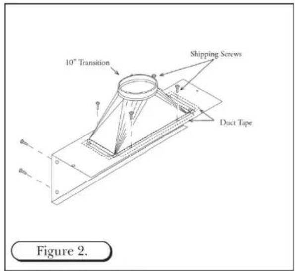
- The hood is shipped with the back panel and the transition. (Note: The transition is shipped upside down within the hood and can be flipped for rear discharge if desired. It must be removed then reinstalled – See Figures 1 though 3)
- Detach the transition from the back panel removing four (4) screws. These shipping screws are needed for re-attaching the transition to the back panel.
- Secure the transition to the top of the back panel, using the four (4) screws provided. Use duct tape to seal the joints of the transition and the top of the back panel. (See Figure 2)
- Secure the back side of the hood to wall stud following building code in your area. (See Figure 3)


WALL HOOD INSTALLATION (continued)
-
Add 2" x 4" wood framing block to aid in securing the top and rear of the hood to the wall. (See Figure 6)
-
To mount CFM300, CFM600 and CFM1200 fans within hood walls. (See Figures 8, 9, 10 & 11)
-
Install the fan by aligning the fan holes with the PEM studs on the back panel. Tighten the fan to the panel using the hex nuts provided. (See Figures 8, 9, 10 & 11)
-
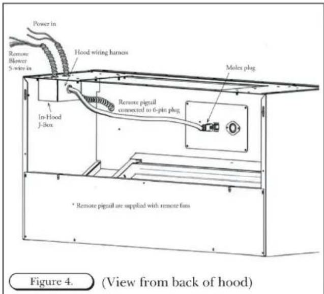
Connect the "Molex" from the fan to the "Molex" plug on the hood. (See Figure 4 from previous page)
-
Attach three wires: black, white and green (#16 AWG) in 12 " conduit from the service panel to the hood junction box. Power supply must be rated for 120v, 60Hz, 15 amps (minimum).
-
Remove the junction box from the rough-in plate. Connect black wire to power supplied black wire, white wire to power supplied white wire and green wire to ground supplied green wire.
-
Place all wiring connectors inside junction box.

OPTIONAL DUCT COVER
-
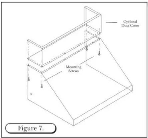
Install the hood as described in "Hood Rough-in Plate Mount" (Note: Be sure to allow enough room for duct cover width on the top section of the rough-in plate.
-
Slide duct cover into opening.
-
Attach Duct Cover from the inside of the hood through filter opening using screws. (See Figure 7) Note: Do not completely tighten screws until all components have been installed. At this point, check the alignment of the duct to the hood. First tighten the four corners to secure the duct, then tighten the remaining screws.
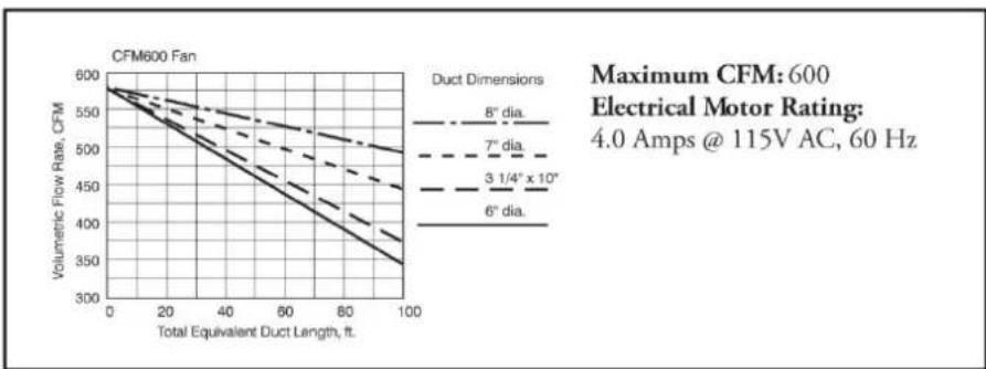
CFM 600 IN-HOOD FAN
WALL APPLICATION - 8" ROUND COLLAR
natural_image
Exploded view diagram of a mechanical assembly with layered components and mounting brackets (no text or labels)Figure 8.

line
| Total Equivalent Duct Length, ft. | 6° dia. | 3 1/4" x 10" | 7° dia. | 8° dia. | | --------------------------------- | ------- | ------------ | ------- | ------- | | 0 | 250 | 250 | 250 | 250 | | 20 | 200 | 180 | 160 | 140 | | 40 | 150 | 130 | 110 | 90 | | 60 | 100 | 90 | 70 | 50 | | 80 | 50 | 40 | 30 | 20 | | 100 | 0 | 0 | 0 | 0 |Maximum CFM: 300
Electrical Motor Rating:
1.79 Amps @ 115V AC, 60 Hz
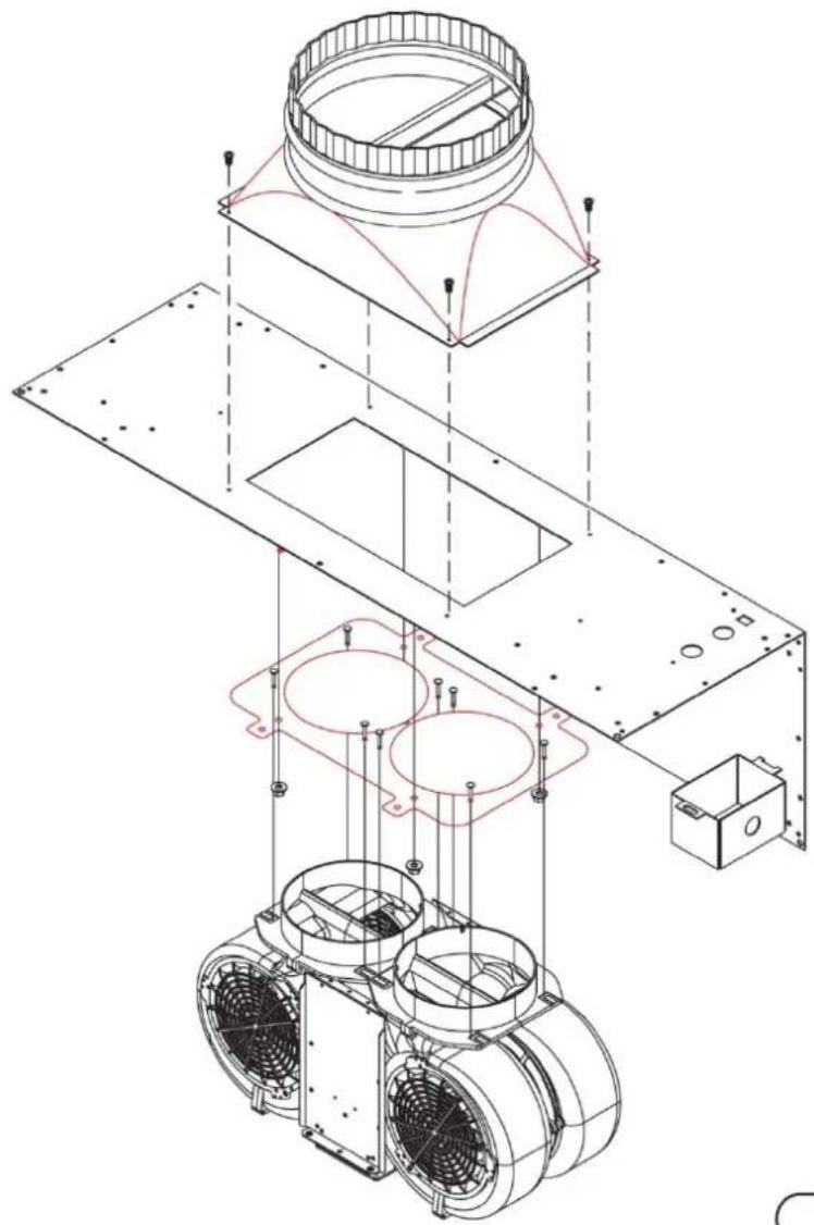
CFM 600 IN-HOOD FAN
natural_image
Technical line drawing of a mechanical assembly with exploded view, showing components like fan, housing, and mounting bracket (no text or labels)Figure 10.
line
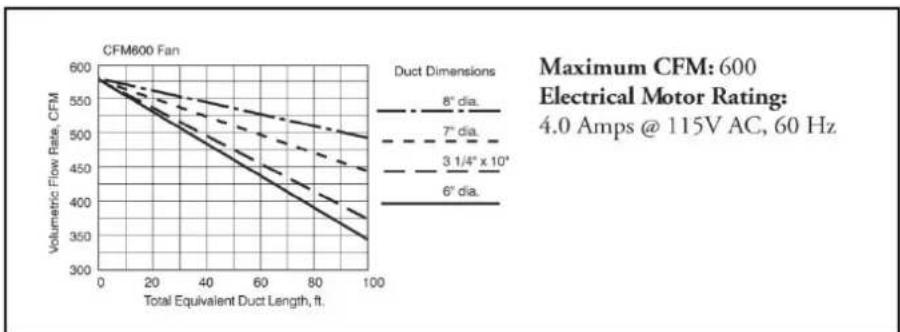
| Total Equivalent Duct Length, ft. | Volumetric Flow Rate, CFM (8" dia.) | Volumetric Flow Rate, CFM (7" dia.) | Volumetric Flow Rate, CFM (3 1/4" x 10") | Volumetric Flow Rate, CFM (6" dia.) | | --------------------------------- | ----------------------------------- | ----------------------------------- | ---------------------------------------- | ---------------------------------- | | 0 | 600 | 600 | 600 | 600 | | 20 | ~550 | ~540 | ~530 | ~520 | | 40 | ~500 | ~490 | ~480 | ~470 | | 60 | ~450 | ~440 | ~430 | ~420 | | 80 | ~400 | ~390 | ~380 | ~370 | | 100 | ~350 | ~340 | ~330 | ~320 |CFM 600 IN-HOOD FAN
CHIMNEY AND ISLAND APPLICATION- 8" TRANSITION

natural_image
Exploded view diagram of a mechanical assembly showing internal components and mounting points (no text or labels)Figure 9.
line
| Total Equivalent Duct Length, ft. | Volumetric Flow Rate, CFM (6° dia.) | Volumetric Flow Rate, CFM (3 1/4" x 10") | Volumetric Flow Rate, CFM (7" dia.) | Volumetric Flow Rate, CFM (8" dia.) | | --------------------------------- | ----------------------------------- | ---------------------------------------- | ---------------------------------- | ---------------------------------- | | 0 | 600 | 600 | 600 | 600 | | 20 | ~550 | ~550 | ~550 | ~550 | | 40 | ~500 | ~500 | ~500 | ~500 | | 60 | ~450 | ~450 | ~450 | ~450 | | 80 | ~400 | ~400 | ~400 | ~400 | | 100 | ~350 | ~350 | ~350 | ~350 |CFM 1200 IN-HOOD FAN
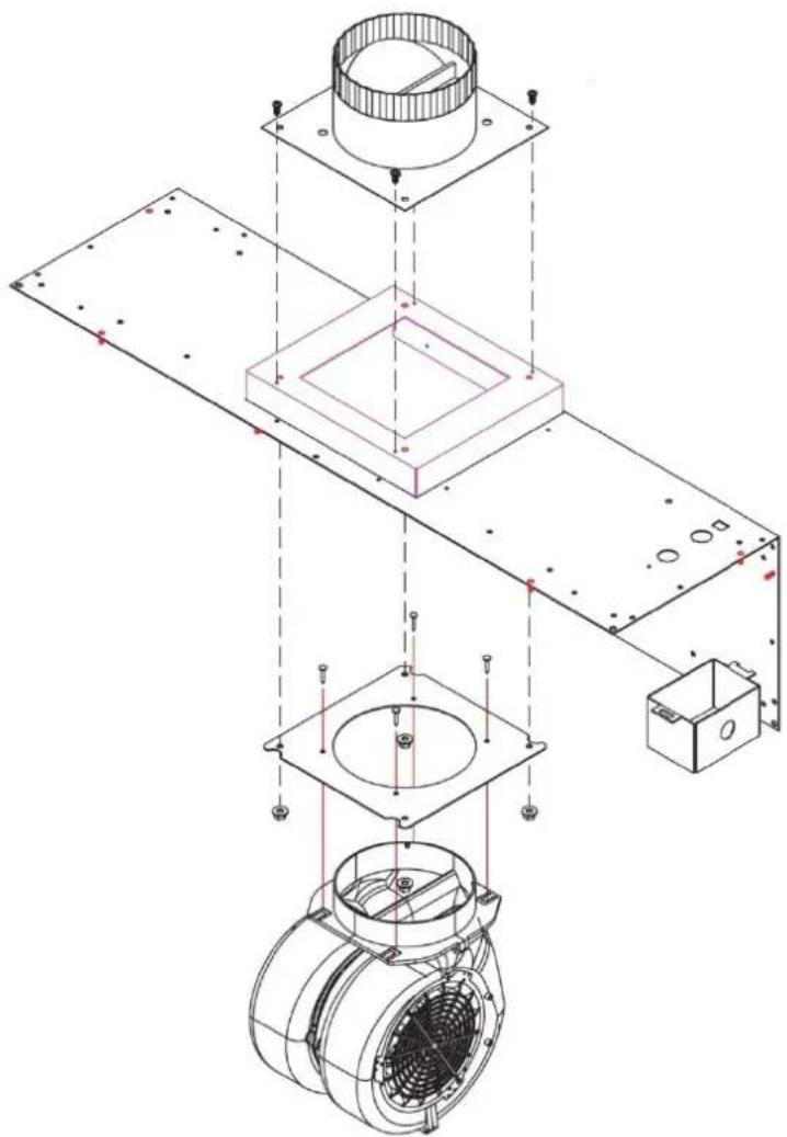
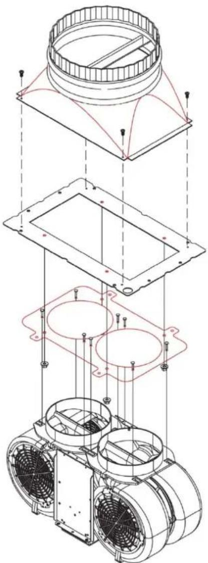
WALL APPLICATION- 10" TRANSITION
natural_image
Technical line drawing of an industrial fan assembly with mounting brackets and internal components (no text or symbols)Figure 11.
line
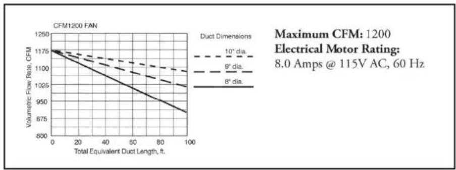
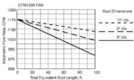
| Total Equivalent Duct Length, ft. | Volumetric Flow Rate, CFM (8° dia.) | Volumetric Flow Rate, CFM (9° dia.) | Volumetric Flow Rate, CFM (10° dia.) | | --------------------------------- | ----------------------------------- | ----------------------------------- | ------------------------------------ | | 0 | 1175 | 1175 | 1175 | | 20 | 1150 | 1140 | 1130 | | 40 | 1125 | 1110 | 1090 | | 60 | 1100 | 1080 | 1050 | | 80 | 1075 | 1050 | 1020 | | 100 | 1050 | 1020 | 990 |CFM 1200 IN-HOOD FAN
CHIMNEY AND ISLAND APPLICATION- 10" TRANSITION
natural_image
Exploded view diagram of a mechanical assembly showing internal components and mounting features (no text or labels)Figure 11.
line
CFM1200 FAN | Total Equivalent Duct Length, ft. | Volumetric Flow Rate, CFM (10° dia.) | Volumetric Flow Rate, CFM (9° dia.) | Volumetric Flow Rate, CFM (8° dia.) | |---|---|---|---| | 0 | 1175 | 1175 | 1175 | | 20 | 1140 | 1130 | 1100 | | 40 | 1105 | 1095 | 1045 | | 60 | 1070 | 1060 | 990 | | 80 | 1035 | 1025 | 935 | | 100 | 1000 | 990 | 875 |Maximum CFM: 1200
Electrical Motor Rating:
8.0 Amps @ 115V AC, 60 Hz
ISLAND HOOD INSTALLATION
INSTALLATION
WARNING: To reduce the risk of fire, use only metal ductwork.
- Decide the placement of the ductwork between the hood and the outside of the home. Your island hood has a top discharge which will run vertically.
- When not installing a remote fan, always install a roof cap or wall cap. Connect rigid round metal ductwork to the roof cap and work back towards the hood location.
- Use duct tape to seal the joints between the ductwork sections.
- A transition with backdraft damper is included with your island hood. It is recommended that the enclosed backdraft damper be used in all installations.
IMPORTANT NOTES:
- Do not place electrical wiring within the duct work itself.
- All island hoods must exhaust to the outdoors.
PREPARATION
- When installing a duct cover, the duct cover must be installed prior to the hood installation. See Figure 14 for duct cover installation instructions.
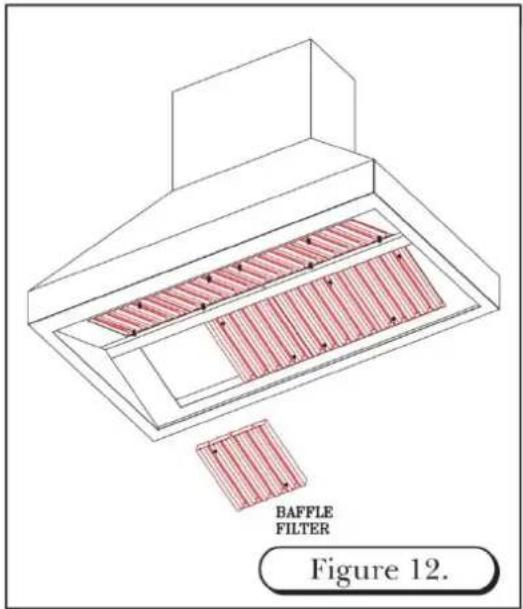
- Remove the baffle filters from hood shell. (See Figure 12)
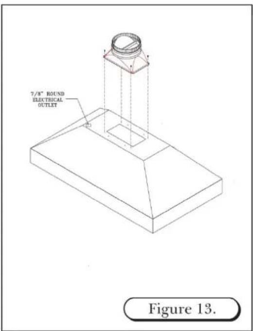
- The hood is shipped with the transition attached. The transition is shipped upside down in the top of the hood and must be removed then reinstalled.
- Detach the transition from the hood by removing the (4) shipping screws. DO NOT discard these screws. These shipping screws will be needed for the reinstallation of the transition to hood.
- Invert the transition (the round collar points away from top of hood). Use the shipping screws removed from step 4.
- When installing a remote fan, drill a 7/8" hole through hood framing for conduit wiring where needed. See Figure 13
ISLAND DUCT COVER INSTALLATION
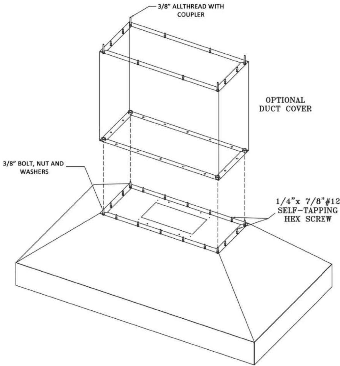
Figure 14.
ISLAND HOOD DUCT WORK INSTALLATION
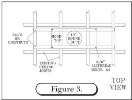
- Cut a 10" diameter opening in the ceiling to accommodate the duct work necessary for proper ventilation.
- Transfer the overall dimensions of the hood top plate onto the finished ceiling/unfinished surface. The top plate width and overall width will vary with the size of the hood.
- Construct the frame using unistrut or wood 2x4's. Due to the weight of the hood, structural support is necessary. (See Figure 3)
- Locate and mark the center of the hood. Attach two wood 2x4's across the top of the ceiling joists. (See Figure 3)
- Drill four 3/8" holes in the 2x4's to match the pattern on the top of the hood. (See Figure 3)
- Remove hood baffle filters prior to installation of hood. (See Figure 12)
WARNING: Framing must be structurally tied together and attached to the ceiling joists to provide enough strength to support the weight of the hood and the internal blower, if applicable.
WARNING: Island hoods are very heavy. A minimum of three installers are required to lift the hood to the ceiling.
WARNING: When making any electrical connections, make sure electrical power is turned off at the power source (or circuit breaker) before proceeding.
- Connect 10" round duct-work to the hood transition using sheet metal screws and/or duct tape.
- Complete all electrical connections. (See Wiring Diagram, pg 22)
-
Align hood and tighten all nuts until hood surface is flush with ceiling. Install #10 x 2" screws through remaining hood mounting holes near top edge of hood surface. This additional support is necessary.
-
If installing an in-hood or in-line fan, DO NOT re-install baffle filters until blower installation is complete. (See in-hood fan installation instructions)

REMOTE FAN
ROOF MOUNT OR WALL MOUNT
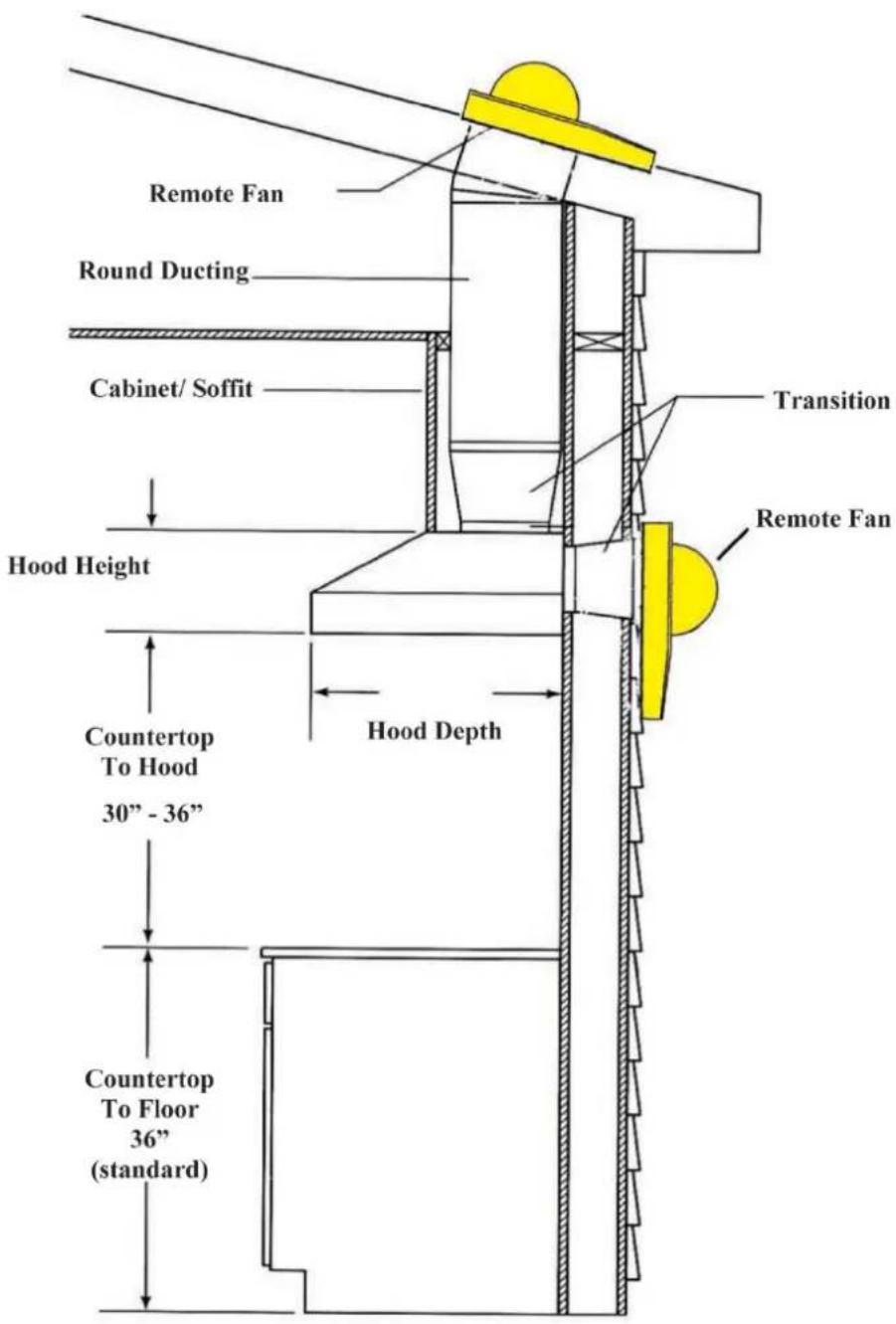
Figure 12.
REMOTE FANS
MODEL
VOLUMETRIC FLOW RATE FOR EQUIVILENT DUCT LENGTHS
APPLICATION
CFMR1000 REMOTE FAN
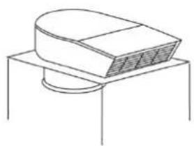
natural_image
Simple line drawing of a mechanical component with a curved top and circular base (no text or symbols)
line
| Total Equivalent Duct Length, ft. | Volumetric Flow Rate, CFM (Duct Dimensions: 6° dia.) | Volumetric Flow Rate, CFM (Duct Dimensions: 3.1/4"x10⁻⁶) | Volumetric Flow Rate, CFM (Duct Dimensions: 7° dia.) | Volumetric Flow Rate, CFM (Duct Dimensions: 8° dia.) | Volumetric Flow Rate, CFM (Duct Dimensions: 9° dia.) | Volumetric Flow Rate, CFM (Duct Dimensions: 10° dia.) | | --------------------------------- | -------------------------------------------------- | ---------------------------------------------------- | -------------------------------------------------- | -------------------------------------------------- | -------------------------------------------------- | -------------------------------------------------- | | 0 | 1000 | 1000 | 1000 | 1000 | 1000 | 1000 | | 20 | ~950 | ~975 | ~985 | ~995 | ~1005 | ~1015 | | 40 | ~850 | ~925 | ~955 | ~975 | ~995 | ~1015 | | 60 | ~750 | ~875 | ~925 | ~965 | ~985 | ~1010 | | 80 | ~650 | ~825 | ~895 | ~945 | ~975 | ~1005 | | 100 | ~550 | ~775 | ~865 | ~925 | ~965 | ~1000 |Maximum CFM: 1000
Electrical Motor Rating:
7.8 Amps @ 115V AC, 60 Hz
Duct Size at Discharge:
10" Square-to-round transition
See ventilator & transition pages for use with hood series.
CFMR1400 REMOTE FAN
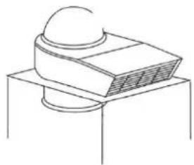
natural_image
Simple line drawing of a computer monitor with a dome on top, placed on a stand (no text or symbols)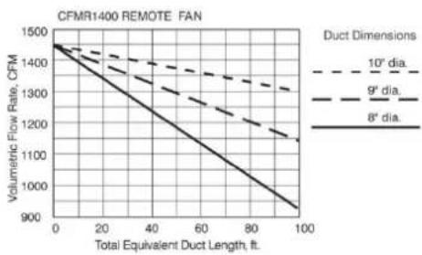
line
| Total Equivalent Duct Length, ft. | Volumetric Flow Rate, CFM (8° dia.) | Volumetric Flow Rate, CFM (9° dia.) | Volumetric Flow Rate, CFM (10° dia.) | | --------------------------------- | ----------------------------------- | ----------------------------------- | ------------------------------------ | | 0 | 1500 | 1500 | 1500 | | 20 | 1350 | 1400 | 1450 | | 40 | 1200 | 1300 | 1400 | | 60 | 1050 | 1200 | 1350 | | 80 | 950 | 1100 | 1300 | | 100 | 900 | 1050 | 1250 |Maximum CFM: 1400
Electrical Motor Rating:
12 Amps @ 115V AC, 60 Hz
Duct Size at Discharge:
10" Square-to-round transition
See ventilator & transition pages for use with hood series.
METAL LINER INSTALLATION
CHECK LOCATION
- If your installation has been roughed-in (including ductwork and wiring), be certain there is nothing in the way of the mounting, pipes, other wiring etc.
- If the installation has not been roughed in, check what is needed to create the framing and mounting hardware (all threads, nuts etc.). Be sure the location will not interfere with wiring, other utilities, or structural considerations.
METAL LINERS - TYPICAL INSTALLATION
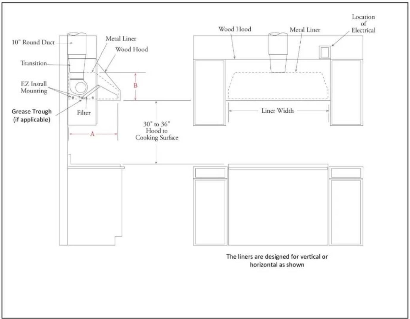
TRANSITION INSTALLATION AND REMOVAL
- The liner is shipped with the back-panel and the transition attached.
- The transition is shipped upside-down in the liner and must be removed then, re-installed.
- If an in-hood fan is furnished, the transition is shipped separately.
- Detach the transition from the back-panel by removing four (4) screws. The shipping screws will be needed for re-installing the transition to the back-panel.
- Secure the transition to the top of the back panel using the four (4) screws that were removed. Use duct tape to seal the joints of the transition and the top of the removable back panel. (See Figure 2 on page 5)
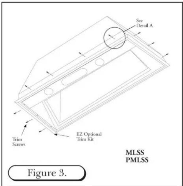
INSTALLING METAL LINERS
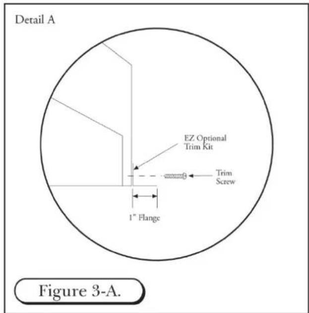
- If the "EZ Optional Trim Kit" will be used, it must be installed prior to mounting the metal liner to the hood shell. Use the provided #8 Phillips head screws. (See Figure 3)
- Lift the metal liner into the hood shell. Due to the weight of the liner, 3 or 4 men may be required to hold the liner in place to insure a tight installation.
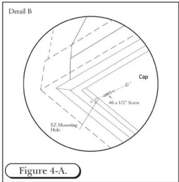
- Install #6 x 1/2" screws through the pre-drilled "EZ Optional Trim Kit" mount holes through to the hood shell. Tap the cover caps into the "EZ Optional Trim Kit" mount holes for a flush appearance. (See Figure 4-A)
- Additional mounting fasteners may be used to secure the liner to the back wall and the ceiling. Access for drilling is through the interior on the liner.

ELECTRICAL CONNECTIONS
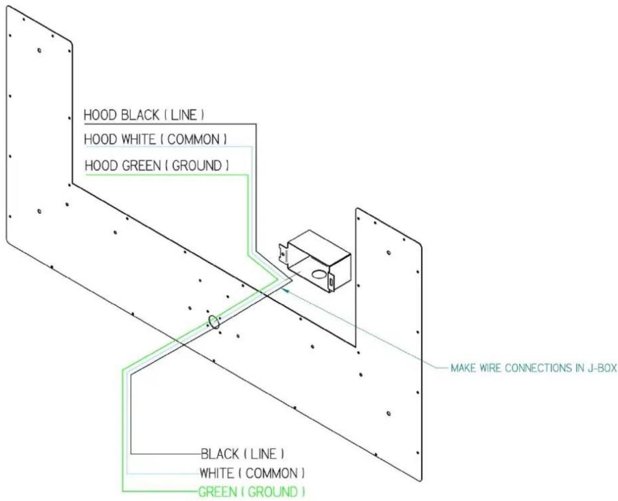
- Install three wires: black, white and green (#16 AWG) in 12 " conduit from the service panel to the hood junction box. Power supply must be rated for 120v, 60 Hz, 15 amps (minimum).
- Remove junction box and run power line through single hole and route to junction box mounted on back.
- Connect black wire to power supplied black wire, white wire to power supplied white wire and green wire to ground supply green wire.
- Place all wiring connectors inside junction box and re-install on back panel.
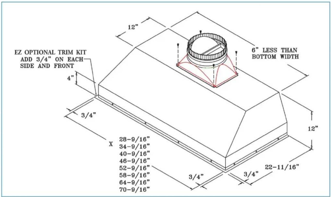
COMPACT METAL LINER SLOPED SIDES (CMLSS)

POSITION OF 8" ROUND COLLAR (TOP VIEW)
SIZE OF THE CUT OUT (BOTTOM VIEW)
METAL LINER SLOPED SIDES (MLSS)

POSITION OF 10" (8") ROUND TRANSITION (TOP VIEW)
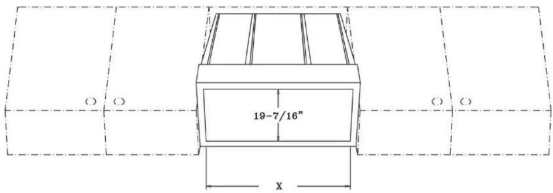
SIZE OF THE CUT OUT - (BOTTOM VIEW)
PROFESSIONAL METAL LINER SLOPED SIDES (PMLSS)
POSITION OF 10" (8") ROUND TRANSITION (TOP VIEW)
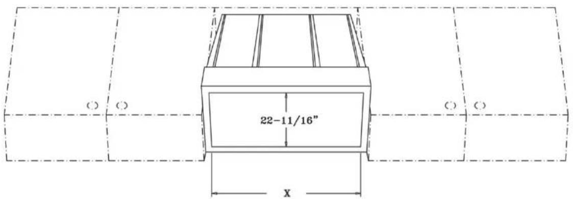
SIZE OF THE CUT OUT (BOTTOM VIEW)
METAL LINER FLAT SIDES (MLFS)
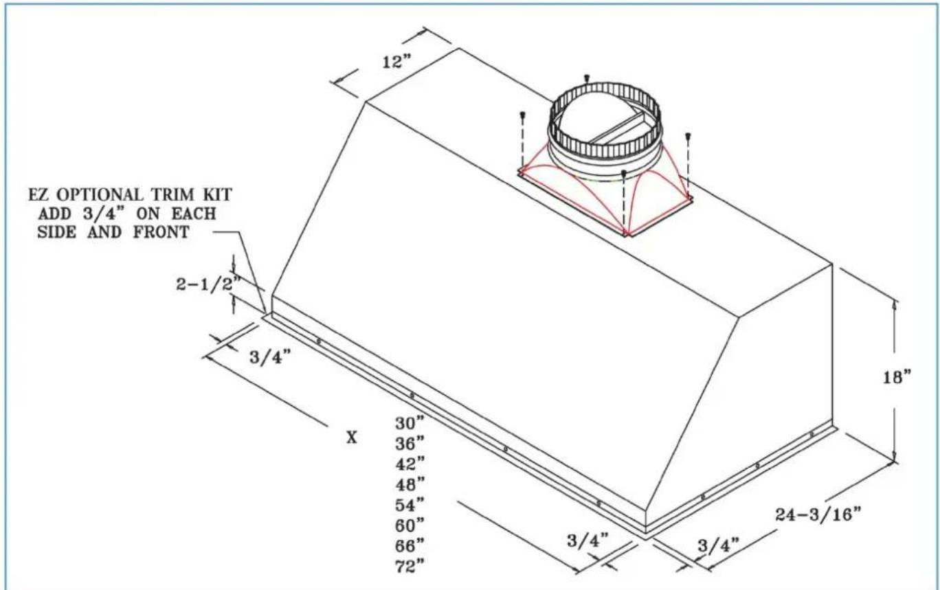
POSITION OF 10" (8") ROUND TRANSITION (TOP VIEW)

SIZE OF THE CUT OUT (BOTTOM VIEW)
CHIMNEY HOOD INSTALLATION
CHECK THE INSTALLATION LOCATION
- If your installation has been roughed-in (including duct work and wiring), be certain there is nothing in the way of the mounting, pipes, other wiring etc.
- If the installation has not been roughed-in, check what is needed to create the framing and mounting hardware (allthreads, nuts, etc.). Be sure the location will not interfere with wiring, other utilities, or structural considerations.
CHOOSE THE INSTALLATION METHOD
- There are several different methods available to mount the hood: the Unistrut, Angle Iron, Frame In, Wall Mounts, Island Mount and Rough-in Plate Mount, which can be used for both indoor and outdoor. Please check the model options for the suggested methods of your installation. Each hood type and site requirements are presented as follows.
- Please read the instructions in their entirety prior to installing the hood.
CONNECTING DUCT WORK
- Ducting should be as short and straight as possible for best fan performance.
- Seal all joints with duct tape.
INSTALLING CHIMNEY STYLE HOODS
-
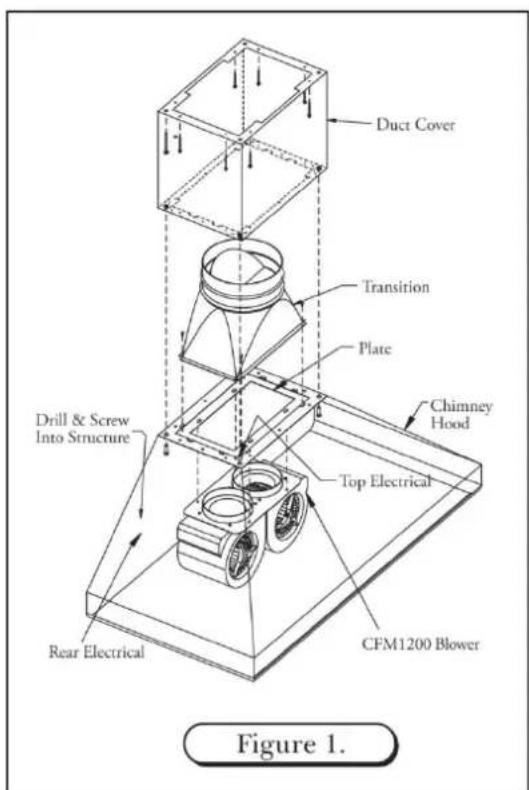
Position the Chimney Hood on its back and locate the transition inside the Chimney Hood; remove the (4) #8 x 12 " self tapping screws at the top of the hood which hold the transition to the hood (save these screws for later use), separate the transition from the hood base and duct cover.
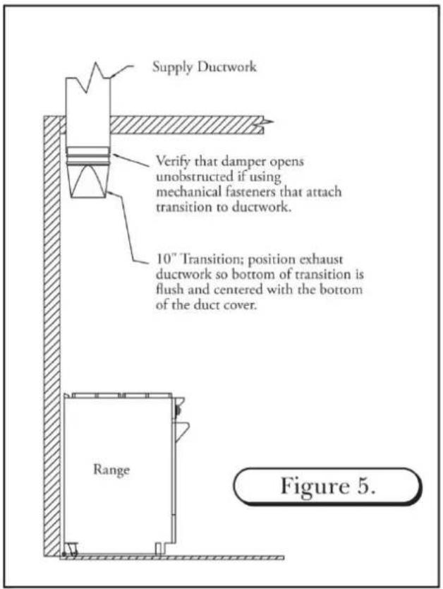
-
Install the transition to the duct work ensuring the bottom of the transition is centered and flush with the bottom of the duct cover. Check the position of the transition by sliding the duct cover over the mounted transition. Verify that the transition is flush, and centered to the bottom of the duct cover. When transition installation is complete, be sure to check that the damper is not hindered from opening if using mechanical fasteners. (See Figure 5)
-
Run electrical supply from rear or top location of hood to hood J-Box(See Figure 2)
-
Install the duct cover to the top of the hood using the 12 – 24 self tapping 7/8" length screws. Also bolt the hood to the duct cover using the supplied stainless steel 3/8" bolts.
-
Before hanging the hood, drill holes in the back of the hood, if necessary, to line up with the structural studs in the wall. Also, be prepared when hanging the hood to feed the electrical either through the top down, or use the hole provided in the back. You may drill a hole in the back, if necessary, to accommodate the electrical. (See Figure 2)
-
Slide the hood up the wall with the transition sliding inside the duct cover, then secure the hood to the back wall (drilling through the back of the hood to locate studs). Use the #10 x 2" long self-tapping screws to secure the hood to the wall structure. (See Figure 6)
-
Once the hood is secure, attach the transition to the rectangular plate at the junction of the hood and duct cover with the screws that were removed from the transition. (See Figure 6)

INSTALLING CHIMNEY STYLE HOODS (continued)
- Electrician may complete electrical connection to hood making the connection at the box inside the hood. (120 volt – See Figure 2) If using a remote fan please see section “Wiring remote Fan”
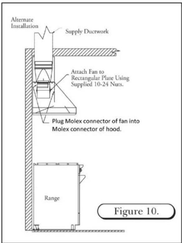
- If using an in-hood CFM600 or CFM1200 fan, slide the fan mount over the studs at the junction of the hood and duct cover and use the 10 – 24 nuts supplied to attach the fan to the hood. (See Figure 10)
IMPORTANT: If installing a 30" wide chimney style hood, please see instructions or mounting a CFM600 in-hood fan.
- Plug the fan Molex connector into the hood Molex connector. (See Figure 10)

ALTERNATE INSTALLATION FOR A CHIMNEY STYLE HOOD

In certain situations the installer may opt for a different installation sequence. The alternate sequence is listed below.
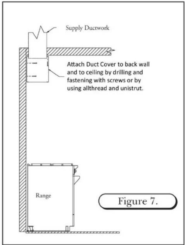
- Drill holes in back of duct cover to align with structural members; fasten duct cover to wall using #10 x 2" self tapping screws; attach duct cover through ceiling opening in top of structure; if available. (See Figure 7)
- Install transition to ductwork, ensuring transition bottom is centered and flush with bottom of duct cover (in most you cases you will not be able to mechanically fasten transition to ductwork. If mechanical fasteners are used, apply duct tape to hold transition in place until hood is mounted. This may be followed by a small amount of silicone at the connection of the transition of ductwork. (See Figure 8)
- Attach the hood to the duct cover. Fasten the hood to back wall (drilling through the back of the hood and duct cover to locate studs. (See Figure 9)
- Continue installation with sequence #7 of standard installation instructions.

INSTALLING A CHIMNEY STYLE HOOD WITH A REAR DISCHARGE THROUGH DUCT COVER
The Chimney Style Hood can adapt to a rear discharge application but with the following limitations:
- A rear discharge application only works when using a 24" tall duct cover or taller. The 12" and 18" tall duct covers do not allow enough room to house the transition (with damper) and an elbow. The rear discharge cannot be made within the hood itself. It can only be made in the duct cover. (See Figure 11)

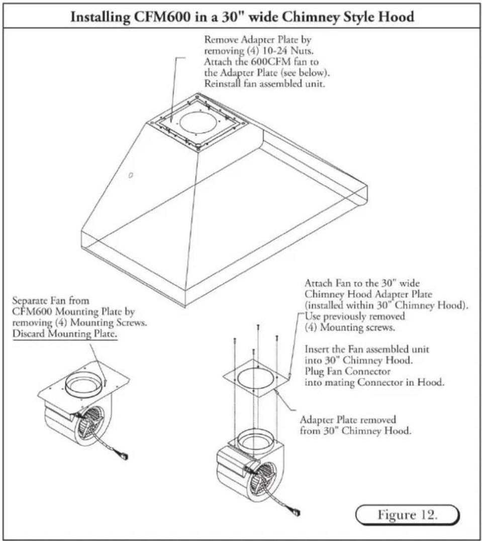
INSTALLING A CFM600 FAN IN A 30" WIDE CHIMNEY STYLE HOOD
These instructions are only applicable when installing a CFM600 fan in a 30" wide chimney style hood.
The Prizer 30" wide chimney style hood has an adapter plate installed inside the hood. In order to install a CFM600 fan within a 30" wide chimney style hood, first remove this adapter plate and use this plate in lieu of the plate shipped with the CFM600 fan.
- Remove the adapter plate from the 30" wide chimney style hood by removing the four (4) 10 – 24 nuts. (See Figure 12)
- Unpack the CFM600 fan (shipped separately).
- Remove the CFM600 fan from the mounting plate by removing the four (4) screws holding the fan to the plate.
- Attach the CFM600 fan to the adapter plate previously removed from the 30" wide chimney style hood.
- Insert the CFM600 fan unit into the 30" wide chimney style hood using the previously removed four (4) 10 – 24 nuts.
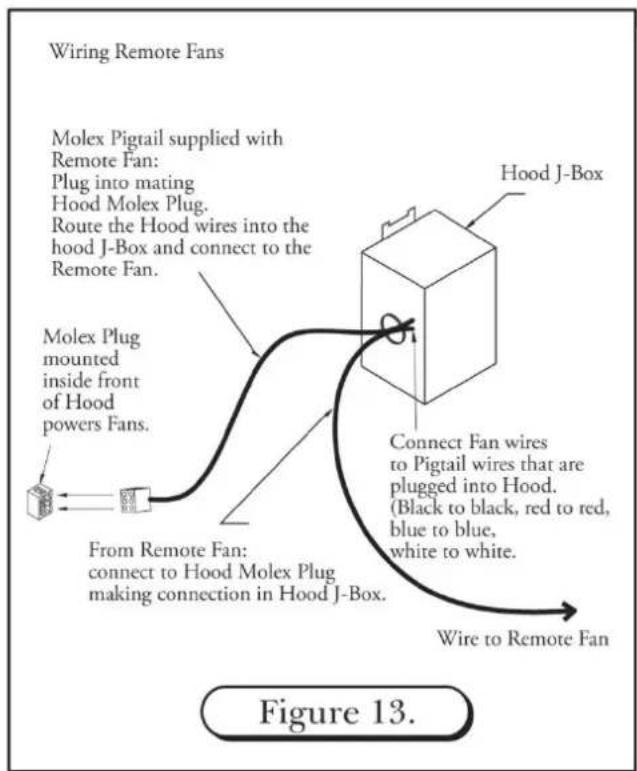
WIRING A REMOTE FAN
When using a remote fan with a chimney style hood, follow the instructions noted below.
NOTE: The chimney style hood is designed to accept a 3-speed fan motor only. It is not designed to accept a variable speed fan.
- The Molex plug mounted within the front portion of the hood supplies power to the remote fan.
- Connect the "male" Molex pigtail (included) with the remote fan to the Molex plug.
- Route the wire ends into the hood's "J-Box".
- Connect these wires to the remote fan wires within the hood's "J-Box". (See Figure 13)
- If using a remote fan for a 30" wide chimney hood, remove and discard the adapter plate. (See Figure 12)
HIGH HEAT SENSOR
A high heat sensor is integrated within the complete line of Prizer Hoods. It is activated when the exhaust temperature reaches 200^ F ( 93^ C) and de-activates as the temperature decreases to 186^ F ( 85^ C). If the fan is operating on the low speed, and the high heat sensor engages, the fan motor will automatically change to high speed until the temperature decreases.
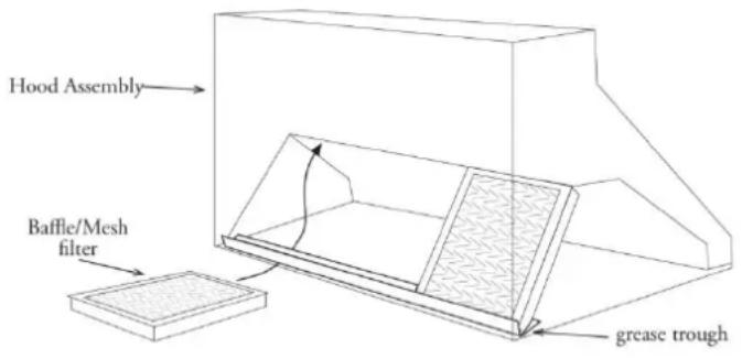
BAFFLE FILTERS, GREASE TROUGHS AND LIGHTS
BAFFLE FILTERS
Your baffle filters come with knobs to aid in filter placement and removal. Grab the knobs with your thumb and index finger. Simultaneously, slide and force the first baffle filter in an upward (slightly pitched) direction towards the ceiling. Spring clips have been attached within the framework to prevent the baffle filters from rattling when fan is operating. These spring clips will make it difficult to insert and remove baffle filters. As the baffle filter is forced upward towards the ceiling, simultaneously swing the lower portion of the filter down and out of the framework. Remove the remaining baffle filters in the same fashion. The first baffle filter removed may be difficult, but the remaining filters will follow with ease.
Baffle filters may be washed in your dishwasher. Simply place on the lower rack of dishwasher using a normal cleaning cycle.
To re-install your new/clean filters within the hood cavity, begin the process but in reverse. First, place the clean “grease trough(s) (if applicable) in the cavity framework followed by the first of the baffle filters keeping in mind the first of the baffle filters will be easy to re-install. The last baffle filter will be difficult due to the tight fit and limited space.
GREASE TROUGHS
The “grease trough” (if applicable) rests within the lowest portion of the rectangular open framework. Check for grease build-up each month. The “grease trough(s) may be wiped free of excess grease and placed on top-shelf of your dishwasher for cleaning.
HALOGEN LIGHTS
Halogen lights are included with the purchase of your hood. To purchase halogen bulbs through Prizer Hoods, you can contact our Customer Service Department or visit your local home improvement store replacing with a PAR 20/PAR16, 50 watt, 120 volt, Halogen Flood.
CONTROLS
Always “turn-on” the hood fan prior to cooking in order to establish an air flow in the kitchen. Allow the fan to remain operating after cooking for a few minutes to clear the air. This measure will ensure the kitchen remains smoke-free & fresher smelling.
FAN
The hood's fan is controlled by a three-speed switch. Speeds Off, Low, Medium and High are printed next to the fan control knob and correspond to the fan speed.
HOOD LIGHTING
The halogen lights are controlled by a single variable light switch or high/low switch.
CLEANING YOUR STAINLESS STEEL HOOD
Keep your hood free of grease build-up under the hood's surface as well as exterior surfaces. Do no use abrasive cloths, steel wool, scrubbing pads or scouring powders. Do not use paper towels or any other coarse cloths for cleaning stainless steel. Micro fiber cloths are recommended for cleaning.
We recommend using a stainless steel cleaning spray to maintain the beautiful luster of your stainless steel hood. Spray the cleaning/polishing solution directly onto a cleaning cloth as opposed to spraying the surface of the hood.
CLEANING RECOMMENDATIONS
Brushed Stainless Steel, Hammered Stainless Steel, European Black Steel and Millennium Disk Stainless
The Brushed Stainless Steel hood should be cleaned with microfiber cloths and stainless steel cleaner. Always wipe in a manner which follows the grain. DO NOT clean with paper towels as they will scratch the surface. Cleaning cloths other than microfiber may scratch the surface of the hood.
Antiquated Copper & Antiquated Brass
The Antiquated Copper and Antiquated Brass hoods should be cleaned twice yearly. Use microfiber cloths and S.C. Johnson Paste Wax available at home improvement stores. Gently apply a small amount in a circular motion using very light pressure. Rubbing too hard may result in the removal of the finish. DO NOT clean with paper towels as scratches will occur. Cleaning cloths other than cotton microfiber may scratch the surface of the hood.
Mirrored Stainless Steel & Powder Coatings
The Mirrored Stainless Steel or Powder Coated hood should be cleaned with microfiber cloths and any spray glass cleaner. DO NOT clean with paper towels, as they will scratch the surface of the hood. Different cleaning cloths other than microfiber may scratch the surface of the hood.
Mirrored Copper, Hammered Copper & Brushed Copper
The Copper hood should be cleaned with microfiber cloths and metal polish. Always wipe in a manner, which follows the grain should a grain pattern exist. DO NOT clean with paper towels, as they will scratch the surface. Different cleaning cloths other than microfiber may scratch the surface of the hood.
Mirrored Brass, Hammered Brass & Brushed Brass
The Brass hood should be cleaned with microfiber cloths and metal polish. Always wipe in a manner, which follows the grain should a grain pattern exist. DO NOT clean with paper towels, as they will scratch the surface. Different cleaning cloths other than microfiber may scratch the surface of the hood.
HOOD INTERIOR
All hoods are fitted with a brushed stainless steel liner. For cleaning, we recommend using microfiber cloths and stainless steel cleaner. Always wipe in a manner, which follows the grain. DO NOT clean with paper towels, as they will scratch the surface of the hood.
BAFFLE FILTERS & GREASE TROUGH
Baffle Filters and Grease Troughs may be cleaned in your dishwasher. The grease troughs should first be cleaned of excess grease with a paper towel, then placed beside the baffle filters in your dishwasher for a thorough cleaning.
TROUBLESHOOTING TIPS
PROBLEM OR CONDITION
Fans and lights do not operate
POSSIBLE SOLUTION
- A fuse may be blown or the circuit breaker tripped. Replace the fuse or reset the breaker.
- Electrical connections at the wiring box may have been made incorrectly. Contact the installer.
Fan runs but lights do not operate • The bulb may have burned out.
- Switch operation may be faulty.
Fan runs but lights do not operate • Connect fan directly to a supply cord, by passing hood control.
- If fan operates, check and replace switch and/or control board.
Excessive fan speed and/or noise • Check for proper installation; excessive length in duct run, number of transitions/elbows and duct diameter.
- Check to ensure fan wheel is not hitting the side of the assembly. Adjust if necessary.
- Check/tighten fan mounts.
- Check for obstructions in damper flap or duct work.
Prizer Hoods reserves the right to change specifications or design without notice. Some models are certified for use in Canada. Prizer Hoods is not responsible for products which are transported from the United States for use in Canada. Check with your local Canadian distributor or dealer.


- BLUESTAR®
- Unleash Your Inner Chef®
- Designer Hoods
- Ventilation Hood Installation Instructions
- TABLE OF CONTENTS
- Wall Hood Installation
- Island Hood Installation
- Metal Liner Installation
- Chimney Hood Installation
- Use & Care
- PLEASE READ COMPLETE INSTRUCTIONS BEFORE PROCEEDING. INSTALLATION MUST COMPLY WITH ALL LOCAL CODES.
- IMPORTANT SAFETY INSTRUCTIONS
- SAFETY PROCEDURES FOR INSTALLING YOUR NEW PRIZER HOOD (continued)
- READ & SAVE: UPON RECEIVING YOUR HOOD
- WALL HOOD INSTALLATION (continued)
- OPTIONAL DUCT COVER
- CFM 600 IN-HOOD FAN
- WALL APPLICATION - 8" ROUND COLLAR
- CHIMNEY AND ISLAND APPLICATION- 8" TRANSITION
- CFM 1200 IN-HOOD FAN
- WALL APPLICATION- 10" TRANSITION
- CHIMNEY AND ISLAND APPLICATION- 10" TRANSITION
- INSTALLATION
- IMPORTANT NOTES:
- PREPARATION
- ISLAND DUCT COVER INSTALLATION
- ISLAND HOOD DUCT WORK INSTALLATION
- REMOTE FAN
- ROOF MOUNT OR WALL MOUNT
- REMOTE FANS
- CHECK LOCATION
- TRANSITION INSTALLATION AND REMOVAL
- INSTALLING METAL LINERS
- ELECTRICAL CONNECTIONS
- COMPACT METAL LINER SLOPED SIDES (CMLSS)
- PROFESSIONAL METAL LINER SLOPED SIDES (PMLSS)
- METAL LINER FLAT SIDES (MLFS)
- CHECK THE INSTALLATION LOCATION
- CHOOSE THE INSTALLATION METHOD
- CONNECTING DUCT WORK
- INSTALLING CHIMNEY STYLE HOODS
- INSTALLING CHIMNEY STYLE HOODS (continued)
- ALTERNATE INSTALLATION FOR A CHIMNEY STYLE HOOD
- INSTALLING A CHIMNEY STYLE HOOD WITH A REAR DISCHARGE THROUGH DUCT COVER
- INSTALLING A CFM600 FAN IN A 30" WIDE CHIMNEY STYLE HOOD
- WIRING A REMOTE FAN
- HIGH HEAT SENSOR
- BAFFLE FILTERS, GREASE TROUGHS AND LIGHTS
- BAFFLE FILTERS
- GREASE TROUGHS
- HALOGEN LIGHTS
- CONTROLS
- FAN
- HOOD LIGHTING
- CLEANING YOUR STAINLESS STEEL HOOD
- CLEANING RECOMMENDATIONS
- Antiquated Copper & Antiquated Brass
- Mirrored Stainless Steel & Powder Coatings
- Mirrored Copper, Hammered Copper & Brushed Copper
- Mirrored Brass, Hammered Brass & Brushed Brass
- HOOD INTERIOR
- BAFFLE FILTERS & GREASE TROUGH
- TROUBLESHOOTING TIPS
- PROBLEM OR CONDITION
- POSSIBLE SOLUTION
Brand : BlueStar
Model : IN042ML
Category : Cap