
LPT-OI513AQ - Camera LG - Free user manual and instructions
Find the device manual for free LPT-OI513AQ LG in PDF.

| Product Type | Indoor/Outdoor Speed Dome Camera |
| Pick-Up Device | 1/4" Super HAD CCD |
| Effective Pixels | NTSC: 410K, PAL: 470K |
| Horizontal Resolution | More than 450 TV lines |
| Lens | 16x optical zoom (F1.6, f=3.9~63 mm) |
| Digital Zoom | 8x (total 128x), variable 2x-8x |
| Minimum Illumination | 1 Lux (30 IRE, AGC On) |
| Pan Range / Speed | 0° – 350° / 120°/sec |
| Tilt Range / Speed | 0° – 90° / 120°/sec |
| Preset Positions | 128 maximum |
| Camera ID | Up to 256 cameras (8-bit DIP switch) |
| Alarm Input | 4 channels (non-voltage contact) |
| Control Protocol | RS-485 (LG, Pelco D/P, etc.) |
| Video Output | Composite 1 Vp-p, 75 Ω (BNC) |
| Power Supply | DC 12V, Class 2, max 10W |
| Dimensions (Ø x H) | 174 x 167.3 mm |
| Weight | Approx. 1.5 kg |
| Operating Temperature | -10°C to +50°C |
| Humidity | Below 80% |
| Special Functions | Auto Pan, Preset Tour, Group Tour, Pattern, Auto Flip, Sensor Linkage |
Frequently Asked Questions - LPT-OI513AQ LG
User questions about LPT-OI513AQ LG
0 question about this device. Answer the ones you know or ask your own.
Ask a new question about this device
Download the instructions for your Camera in PDF format for free! Find your manual LPT-OI513AQ - LG and take your electronic device back in hand. On this page are published all the documents necessary for the use of your device. LPT-OI513AQ by LG.
USER MANUAL LPT-OI513AQ LG
Before installing and using the camera, please read this owner's manual carefully and retain for future reference.


CAUTION
RISK OF ELECTRIC SHOCK DO NOT OPEN

CAUTION: TO REDUCE THE RISK
OF ELECTRIC SHOCK
DO NOT REMOVE COVER (OR BACK)
NO USER-SERVICEABLE PARTS INSIDE
REFER SERVICING TO QUALIFIED SERVICE
PERSONNEL.

This lightning flash with arrowhead symbol within an equilateral triangle is intended to alert the user to the presence of uninsulated dangerous voltage within the product's enclosure that may be of sufficient magnitude to constitute a risk of electric shock to persons.

The exclamation point within an equilateral triangle is intended to alert the user to the presence of important operating and maintenance (servicing) instructions in the literature accompanying the product.
FCC WARNING : This equipment may generate or use radio frequency energy. Changes or modifications to this equipment may cause harmful interference unless the modifications are expressly approved in the instruction manual. The user could lose the authority to operate this equipment if an unauthorized change or modification is made.
REGULATORY INFORMATION: FCC Part 15
This equipment has been tested and found to comply with the limits for a Class A digital device, pursuant to Part 15 of the FCC Rules. These limits are designed to provide reasonable protection against harmful interference when the equipment is operated in a commercial environment.
This equipment generates, uses, and can radiate radio frequency energy and, if not installed and used in accordance with the instruction manual, may cause harmful interference to radio communications. Operation of this equipment in a residential area is likely to cause harmful interference in which case the user will be required to correct the interference at his own expense.
- A suitable conduit entries, knock-outs or glands shall be provided in the cable entries of this product in the end user.
- Caution: Danger of explosion if battery is incorrectly replaced. Replaced only with the same or equivalent type recommended by the manufacturer. Dispose of used batteries according to the manufacturer's instructions.
- Holes in metal,,through which insulated wires pass,shall have smooth well rounded surfaces or shall be provided with brushings.
Warning: Do not install this equipment in a confined space such as a bookcase or similar unit.
Warning: Wiring methods shall be in accordance with the National Electric Code, ANSI/NFPA 70.
Warning: This is a class A product. In a domestic environment this product may cause radio interference in which case the user may be required to take adequate measures.
Warning: To reduce a risk of fire or electric shock, do not expose this product to rain or moisture.
Caution: This installation should be made by a qualified service person and should conform to all local codes.
Caution: To avoid electrical shock, do not open the cabinet. Refer servicing to qualified personnel only.
Caution: The apparatus should not be exposed to water (dripping or splashing) and no objects filled with liquids, such as vases, should be placed on the apparatus.

Disposal of your old appliance
- When this crossed-out wheeled bin symbol is attached to a product it means the product is covered by the European Directive 2002/96/EC.
- All electrical and electronic products should be disposed of separately from the municipal waste stream via designated collection facilities appointed by the government or the local authorities.
- The correct disposal of your old appliance will help prevent potential negative consequences for the environment and human health.
- For more detailed information about disposal of your old appliance, please contact your city office, waste disposal service or the shop where you purchased the product.
CE This product is manufactured to comply with the EEC DIRECTIVE 89/336/EEC, 93/68/EEC and 2006/95/EC.
IMPORTANT SAFETY INSTRUCTIONS
CAUTION: PLEASE READ AND OBSERVE ALL WARNINGS AND INSTRUCTIONS IN THIS OWNER'S MANUAL. AND THOSE MARKED ON THE PRODUCT. RETAIN THIS BOOKLET FOR FUTURE REFERENCE.
This product has been designed and manufactured to assure personal safety. Improper use can result in electric shock or fire hazard. The safeguards incorporated in this product will protect you if you observe the following procedures for installation, use, and servicing.
This product does not contain any parts that can be repaired by the user.
DO NOT REMOVE THE CABINET COVER, OR YOU MAY BE EXPOSED TO DANGEROUS VOLTAGE. REFER SERVICING TO QUALIFIED SERVICE PERSONNEL ONLY.
- Read these instructions. - All these safety and operating instructions should be read before the product is operated.
- Keep these instructions. - The safety, operating and use instructions should be retained for future reference.
- Heed all warnings. - All warnings on the product and in the operating instructions should be adhered to.
- Follow all instructions. - All operating and use instructions should be followed.
- Do not use this apparatus near water. - For example: near a bath tub, wash bowl, kitchen sink, laundry tub, in a wet basement; or near a swimming pool; and other areas located near water.
- Clean only with dry cloth. - Unplug this product from the wall outlet before cleaning. Do not use liquid cleaners.
- Do not block any ventilation openings. Install in accordance with the manufacturer's instructions. - Slots and openings in the cabinet are provided for ventilation and to ensure reliable operation of the product and to protect it from over-heating. The openings should never be blocked by placing the product on a bed, sofa, rug or other similar surface. This product should not be placed in a built-in installation such as a bookcase or rack unless proper ventilation is provided or the manufacturer's instructions have been adhered to.
- Do not install near any heat sources such as radiators, heat registers, stoves, or other apparatus (including amplifiers) that produce heat.
-
Do not defeat the safety purpose of the polarized or grounding-type plug. A polarized plug has two blades with one wider than the other. A grounding type plug has two blades and a third grounding prong. The wide blade or the third prong are provided for your safety. If the provided plug does not fit into your outlet, consult an electrician for replacement of the obsolete outlet.
-
Protect the power cord from being walked on or pinched particularly at plugs, convenience receptacles, and the point where they exit from the apparatus.
- Only use attachments/accessories specified by the manufacturer.
- Use only with the cart, stand, tripod, bracket, or table specified by the manufacturer, or sold with the apparatus. When a cart is used, use caution when moving the cart/apparatus combination to avoid injury from tip-over.

natural_image
Silhouette of a person pushing a cart with a diagonal arrow, enclosed in a circle (no text or symbols)-
Unplug this apparatus during lightning storms or when unused for long periods of time.
-
Refer all servicing to qualified service personnel. Servicing is required when the apparatus has been damaged in any way, such as power-supply cord or plug is damaged, liquid has been spilled or objects have fallen into the apparatus, the apparatus has been exposed to rain or moisture, does not operate normally, or has been dropped.
Introduction
Contents
Introduction 4-7
IMPORTANT SAFETY INSTRUCTIONS .....3
Contents 4
About Dome Camera 4
Features 4-5
Safety Precautions 6
Identification of Camera 7
Installation 8-13
Precautions 8
Removing the Protection Tape 8
Mounting the Camera 8-9
- Ceiling mount 8
• Surface mount (Optional) 8
- Pendant mount (Optional) 9
• Wall mount (Optional) 9
Setting the Switch 10-13
• RS-485 Parameter Setup .....10
• Camera ID Setting .....11-13
Connections 14-17
Precautions 14
RS-485 Connection 14
ALARM IN Connections .....15
System Connection 17
Adapter Connections .....17
Setup Menu 18-23
Setup Menu Overview .....18
Setting Camera Menu 19
- Open Menu Display 19
• To reset your parameters to the factory default settings .....19
- Backlight Setting ....20
• Color Setting .....20
- Negative Setting ....20
• Focus Mode setting .....20
- Flickerless Setting ....21
- Setting the WBC (White Balance Control) Mode 21
• Camera Identification Setting .....22
- Sharpness Setting .....22
- Brightness Setting .....22
- Zoom Start setting ....22
- Zoom End setting .....22
• Focus Distance setting .....23
• AE Mode setting .....23
Reference 24
Specifications 24
About Dome Camera
The dome cameras are designed for installation in an indoor/outdoor video surveillance system.
The camera incorporates the digital signal processor, pan/tilt mechanism, x16 zoom lens and RS-485 communication interface in a compact outdoor enclosure.
A newly developed 1/4" CCD makes the camera suitable for use under extremely low illumination conditions as well as in daylight.
Features
■ High Sensitivity Support
The camera provides the high quality picture with 1/4" Super HAD CCD effective pixels.
■ Preset Position
Preset position is the function to register camera monitoring positions (preset positions) associated with position numbers. By entering the position numbers, you can move cameras to the preset positions.
A maximum of 128 Preset Position is available.
The moving speed and holding time are adjustable.
■ Preset Tour
You can tour all preset positions that has already been registered.
■ Preset Group Tour
You can create a preset group using the preset positions that has already been registered (maximum 9 groups) and you can tour the preset position within the group.
A preset group should have a maximum of 8 preset positions.
■ Pattern Function
A routine of manual operations can be stored for 5 minutes at the maximum and reproduced repetitively. The Panning, Tilting and Zoom controls are available for recording the pattern.
Note: The available total time of pattern differs depending on camera's operation. When the time is over, the pattern setup will automatically stop.
■ Auto Pan
The camera has an Auto Pan function that enables to keep surveillance on every detail occurring around the specific area, which is preset to watch in advance.
The camera can pan among the maximum 8 points you will set. The moving speed and holding time are adjustable.
■ Auto Flip
The Auto flip function allows the tilt angle to widen up to 180°. The image on the monitor screen is flipped horizontally and vertically at the tilt angle of approx. 90°.
Note: The Auto Flip function may not be operated at any position.
■ Sophisticated Design
This is the surveillance camera that can fit any indoor surroundings because it comes in the compact size and sophisticated design.
■ Zoom Lens & Auto Focus
Zooming is possible from 16 times (the optical zoom limit), to a maximum of X8 times digital zoom.
■ Sensor Linkage
The camera is capable of capturing a subject by the focus of camera moving promptly toward the subject at the rate of 120^/sec when the camera works with a detector (magnetic, beam, infrared rays), and a subject moving within a detection area is captured by a detector.
■ Alarm In function
Alarm input signals are supplied from external devices through the ALARM IN connector to turn the camera to a preset position.
■ Controls by General Controller
This camera can be controlled by RS-485. Especially the camera has an excellent cost-saving effect because it can be controlled by the general RX point of contact signal.
■ Connects with the maximum 256 cameras
This camera can be utilized after being connected with maximum 256 cameras. Therefore, it is capable of performing an excellent job in the large buildings or department stores.
Note: During Auto Pan, Preset Tour, or Pattern Record/Play, you can use only STOP key or Joystick on the controller.
■ Power Supply
This camera must always be operated a DC 12V Certified/Listed, class 2 power supply only.
Safety Precautions
■ Do not attempt to disassemble the camera
To prevent electric shock, do not remove screws or covers. There are no user serviceable parts inside. Ask a qualified service personnel for servicing.
■ Avoid the camera with direct sunlight
Do not aim the camera at bright objects. Whether the camera is in use or not, never face it with direct sunlight or other extremely bright objects. Otherwise blooming or smear may be caused.
■ Handle the camera with care
Do not abuse the camera. Avoid striking, shaking, etc. The camera could be damaged by improper handling or storage.
■ Do not use strong solvents or detergents
Use a dry cloth to the camera when it is dirty. If it is hard to remove the dirt on the camera, use a mild detergent and wipe it gently.
■ Do not install this camera upside down
This camera is designed for mounting on the ceiling or wall. If you install this camera upside down, for example, mounted on the floor, it may cause malfunction.
■ Do not use the camera in such places as shown below.
The lens may become cloudy due to condensation if the camera is used under the following conditions.
- Rapid temperature fluctuation by switching an air conditioner on and off.
- Rapid temperature fluctuation due to frequent door opening and closing.
- Use in an environment where eyeglasses become foggy.
- Use in a room filled with cigarette smoke or dust.
If the lens becomes cloudy due to condensation, remove the dome cover and wipe all moist surfaces with a soft cloth.
■ Before operating, please check proper temperature, humidity and power source ratings.
Use the camera under conditions where temperature is between -10 °C – +50 °C and humidity is below 80%.
The input power source is DC 12V.
■ Consumables
Parts having contacts such as the lens-drive motors, cooling fan built inside the camera are subject to wear with time. About replacement and maintenance of such parts, please ask the nearest service center.
Identification of Camera
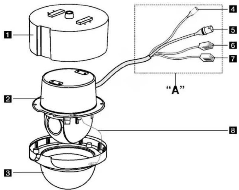
1 Camera mounting bracket
The bracket is optional for surface installation.
2 Dome camera body
3 Dome cover
4 Power cable (DC 12V)
5 Video output cable with BNC connector Connects with the video connector of the monitor.
6 Data Communication Port (RJ45) - RS-485 and Alarm Input
7 Data Communication Port (RJ45) - RS-485 and Alarm Input
8 Fall Prevention Wire
Be sure to hook the fall prevention wire into an bracket.
“A” Do not expose cable connection part to outdoor such as rain, moisture environment. It may cause waterproof problem. But if you are indeed. Sealing them tightly.
Installation
Precautions
- The following steps of installation and connection work should be done by qualified service personnel or system installers and should conform to all local codes.
- Be sure to switch the camera off before installation and connection.
- Do not install the camera near the air outlet of an air conditioner.
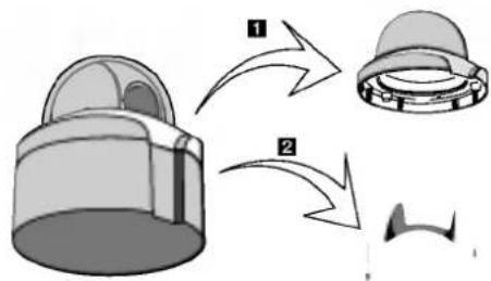
Removing the Protection Tape
Before using the camera, remove the protection tape. Caution: Remove the protection tape carefully.
- Loosen the screws using the wrench and remove the dome cover as shown below.
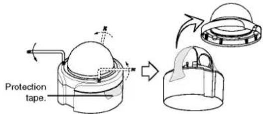
- Remove the protection tape and attach the dome cover.

natural_image
Diagram showing a mechanical device before and after assembly, with no visible text or symbolsMounting the Camera
The figures show an example of the camera mounted on a ceiling or wall with a locally procured bracket. Refer to the instructions included with the bracket for filling gaps and holes with waterproof material.
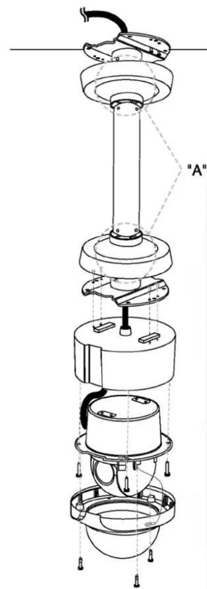
Ceiling mount
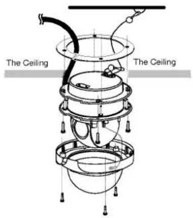
Surface mount (Optional)

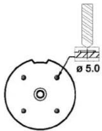
Note:
When you install the camera to the ceiling mount, you must drill a hole in the camera body as shown right. (σ5.0)
Pendant mount (Optional)
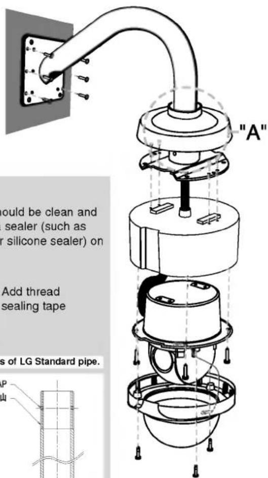
Wall mount (Optional)
■ How to install
"A" Pipe threads should be clean and rust free. Use a sealer (such as Teflon™ tape or silicone sealer) on the threads.

Reference: Specifications of LG Standard pipe.

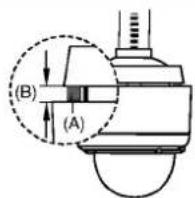
Note:
Do not remove the block (A) to keep the gap (B) between the camera body and installation bracket.
Setting the Switch
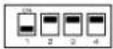
The DIP switch of the camera is two 4-bit switches and employs RS-485 communication mode as basic use. Switch settings are read into the camera when the power is turned on. Make sure to turn it off, then turn it back after changing the switch settings.
RS-485 Parameter Setup
The selected protocol, communication parameters, and set unit numbers are read into the camera when power is switched on.
- Turn off the camera.
- Remove the dome cover from the camera as shown below.
- Set the DIP switch on the bottom part of the camera according to the function shown in the table of the below.

| Switch position (SW101) | Function Effect | |
 | (ON ON ON ON) | When the camera is connected to the controller with LG protocol. The controller with LG protocol allow only limited control for this camera. |
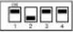 | (ON OFF ON ON) | When the camera is connected to the controller with LG Multix protocol. The controller with LG Multix protocol allow all control for this camera. |
 | OFF ON ON ON | Reserved 1 (Pelco D protocol) |
| OFF OFF ON ON | Reserved 2 (Pelco P protocol) | |
 | ON ON OFF ON | Reserved 3 |
| OFF ON OFF ON | Reserved 4 | |
 | ON OFF OFF ON | Reserved 5 |
| OFF OFF OFF ON | Reserved 6 | |
 | ON ON ON OFF | Reserved 7 |
| OFF ON ON OFF | Reserved 8 | |
 | ON OFF ON OFF | Reserved 9 |
| OFF OFF ON OFF | Reserved 10 | |
 | ON ON OFF OFF | Reserved 11 |
| OFF ON OFF OFF | Reserved 12 | |
 | ON OFF OFF OFF | Reserved 13 |
| OFF OFF OFF OFF | Reserved 14 | |
Note: If you are not using the controller with LG protocol, there may be some limitation of function control.
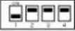
| Switch position (SW104) | BAUD RATE | |
 | (OFF OFF OFF OFF) | 9,600 BPS |
 | (OFF OFF OFF ON) | 1,200 BPS |
 | (OFF OFF ON OFF) | 2,400 BPS |
 | (OFF OFF ON ON) | 4,800 BPS |
 | (OFF ON OFF OFF) | 19,200 BPS |
 | (OFF ON OFF ON) | 38,400 BPS |
 | (OFF ON ON OFF) | 57,600 BPS |
 | (OFF ON ON ON) | 115,200 BPS |
- Turn on the camera. Setup is completed.
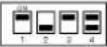
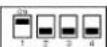
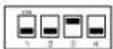
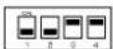
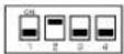
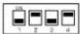
Camera ID Setting
This camera has the camera ID set to "1" at the time of the shipment. If you use 2 cameras or more simultaneously, change the ID to "2" using the 8-bit DIP switch of the 2 camera with a screwdriver.
Set the camera ID setting referring to the pictures and the table on the below.
• The default setting of the camera ID is 1.

SW102
The table for the camera ID setting
- The connections should be made by qualified service personnel or system installers in accordance with all local codes.
• DC 12V can be used.
Note: When powered up, the unit performs a self-check (including one panning, tilting, zooming and focusing operation).
RS-485 Connection
Use the cable that is described below for RS-485 site communication.
• Shielded, twisted pair cable
- Low impedance
- Wire gauge size is thicker than AWG #22 (0.33 mm ^2 ).
ALARM IN Connections
An 8-pin harness are supplied with the camera as standard accessories. Connect external sensors to this connector. Input specifications are low-active, non-voltage contact (ON when active) or open collector (Low when active).
Cautions
- Alarm input connection must be connected to only one port of two communication ports.
- Do not connect one alarm sensor to the several camera's alarm input connector.
What is Alarm Input function?
This speed dome camera has a terminal that can sense the alarm signals.
If the alarm sensor that has installed in a door, window, safe etc. sense a touch or shock, the alarm sensor send the alarm signal to the camera and the camera will observe the sensed position.
There are "Manual mode" and "Auto mode" for the Alarm Input function.
- Manual mode: Change the observe position to a sensor that senses a touch or shock then keep observe the sensed position. (Set the Duration Time of Alarm Input function to "0".)

flowchart
graph TD
    A["Before inputting the alarm signal"] --> B["Alarm signal input"]
    B --> C["Preset 1"]
    B --> D["Preset 2"]
    B --> E["Preset 3"]
    C --> F["Alarm 1"]
    D --> G["Alarm 2"]
    E --> H["Alarm 3"]
- Auto mode: Change the observe position to a sensor that senses a touch or shock then return to the position that previously observed. . (Set the Duration Time of Alarm Input function to "1 to 255".)

flowchart
graph TD
    A["Before inputting the alarm signal"] --> B["Released alarm signal"]
    B --> C["Preset 1"]
    B --> D["Preset 2"]
    B --> E["Preset 3"]
    B --> F["Alarm 1"]
    B --> G["Alarm 2"]
    B --> H["Alarm 3"]
Note : The Alam In 1 is Preset 1, Alam In 2 is Preset 2, Alam In 3 is Preset 3 and Alam In 4 is Preset 4.
Alarm Input function
Listed below are the camera actions of alarm input function by different function status in each mode
| Function status | Manual mode | Auto mode |
| While observe a specific position. | Change the observe position to the alarmed position then keep observe the alarmed position. | Change the observe position to the alarmed position then return to the position that previously observed. |
| While operating Preset Tour function. | Stop preset touring and change the observe position to the alarmed position then keep observe the alarmed position. | Stop preset touring and change the observe position to the alarmed position then restart the preset touring again. |
| While operating Auto Pan function. | Stop auto panning and change the observe position to the alarmed position then keep observe the alarmed position. | Stop auto panning and change the observe position to the alarmed position then restart the auto panning again. |
| While operating Pattern function. | Stop operating pattern function and change the observe position to the alarmed position then keep observe the alarmed position. | Stop operating pattern function and change the observe position to the alarmed position then restart the pattern function again. |
System Connection
Note: When any peripheral is turned off and turned on again, the camera is also turned off and turned back on.

flowchart
graph TD
    A["Controller"] --> B["DVR"]
    B --> C["RS-485 Connection (TRX D+, TRX D-)"]
    C --> D["Alarm In #1"]
    C --> E["Alarm In #2"]
    C --> F["Alarm In #3"]
    C --> G["Alarm In #4"]
    H["RS-485 Connection (TRX D+, TRX D-)"] --> I["Adapter (Supplied)"]
    I --> J["Caution: Connect the supplied termination adapter to the final camera's data port to prevent the RS-485 communication error."]
    style A fill:#f9f,stroke:#333
    style H fill:#ccf,stroke:#333
    style J fill:#cfc,stroke:#333
Caution: Do not connect the alarm connectors to the another camera's alarm connectors.
Adapter Connections
The adapter is used to connect to another camera, alarm sensor, or controller with RS-485 protocol, etc.

flowchart
graph TD
    A["Input"] --> B["Brown"]
    A --> C["Blue"]
    A --> D["Yellow"]
    A --> E["Green"]
    A --> F["Red"]
    A --> G["Black"]
    A --> H["Orange"]
    A --> I["White"]
    B --> J["1 ALARM IN 1"]
    C --> K["2 ALARM IN 2"]
    D --> L["3 GND"]
    E --> M["4 TRX D-"]
    F --> N["5 TRX D+"]
    G --> O["6 GND"]
    H --> P["7 ALARM IN 3"]
    I --> Q["8 ALARM IN 4"]
    J --> R["To Alarm sensor"]
    K --> S["To Alarm sensor"]
    L --> T["TXD -"]
    M --> U["TXD +"]
    N --> V["RS-485 Connection"]
    O --> W["RS-485 Connection"]
    P --> X["RS-485 Connection"]
    Q --> Y["RS-485 Connection"]
Setup Menu
Setup Menu Overview
Setup menus are shown in the table right. You can adapt the camera to your requirements by setting up the respective items in these menus. These menus are described on the following pages for reference. Switches and keys on the controller are used in the setup operations.
Note: The Preset, Auto Pan, Pattern, Alarm functions could not be set on the OSD menu. To set these functions, use LCC-K1000 protocol or Multix protocol.
| Menu Option | Page |
| INITIAL SET | 19 |
| BACKLIGHT | 20 |
| COLOR | 20 |
| NEGATIVE | 20 |
| FOCUS | 20 |
| FLICKERLESS | 21 |
| WBC MODE | 21 |
| CAMERA ID | 22 |
| SHARPNESS | 22 |
| BRIGHTNESS | 22 |
| ZOOM START | 22 |
| ZOOM END | 22 |
| FOCUS FROM | 23 |
| AE MODE | 23 |
Setting Camera Menu
The buttons on the connected controller are used for setup.
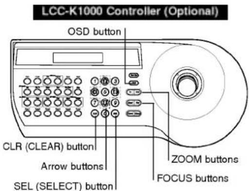
Open Menu Display
- Select the number of the camera you want to set up and a monitor to display MENU.
- Press OSD button on the controller.
Note: Please refer to the manuals of the controller for details. - Use ZOOM (In/Out) to select an option.
| MENU 1 | |
| INITIAL SET | ON |
| BACKLIGHT | OFF |
| COLOR | ON |
| NEGATIVE | OFF |
| FOCUS | PUSH AUTO |
| FLICKERLESS | OFF |
| WBC MODE | AUTO |
| MENU 2 | |
| CAMERA ID | OFF |
| SHARPNESS | 10 |
| BRIGHTNESS | 42 |
| ZOOM START | x1 |
| ZOOM END | x128 |
| FOCUS FROM | 50Cm |
| AE MODE | AUTO |
- Use FOCUS (Near/Far) to select a value.
- To close MENU, press OSD on the controller.
To reset your parameters to the factory default settings
Use ZOOM (In/Out) to select [INITIAL SET] option then press FOCUS (Near/Far) to select [YES].
Backlight Setting
Improves an image that is darkened because of backlighting.
Select [BACKLIGHT] option on the MENU 1, then select a value.
| MENU 1 | |
| INITIAL SET | ON |
| BACKLIGHT | OFF |
| COLOR | ON |
| NEGATIVE | OFF |
| FOCUS | PUSH AUTO |
| FLICKERLESS | OFF |
| WBC MODE | AUTO |
• OFF: The back light compensation is not used.
• ON: The back light compensation is used.
Color Setting
You can switch the displayed picture to grayscale or color.
Select [COLOR] option on the MENU 1, then select an option (ON or OFF). Set to [ON] to display the picture with color. Set to [OFF] to display the picture with grayscale.
| MENU 1 | |
| INITIAL SET | ON |
| BACKLIGHT | OFF |
| COLOR | ON |
| NEGATIVE | OFF |
| FOCUS | PUSH AUTO |
| FLICKERLESS | OFF |
| WBC MODE | AUTO |
Negative Setting
You can use the negative effect.
Select [NEGATIVE] option on the MENU 1, then select an option (ON or OFF).
| MENU 1 | |
| INITIAL SET | ON |
| BACKLIGHT | OFF |
| COLOR | ON |
| NEGATIVE | OFF |
| FOCUS | PUSH AUTO |
| FLICKERLESS | OFF |
| WBC MODE | AUTO |
Focus Mode setting
Select [FOCUS MODE] option on the [FOCUS] menu, then select the following mode.
- PUSH AUTO: Auto-focus is activated only when the Push Auto key on the controller is pressed.
- MANUAL/AUTO: Focus is activated only when the FOCUS (NEAR or FAR) keys on the controller is pressed. Auto-focus is activated automatically while a manual pan, tilt or zoom operation is performed.
Notes:
- If you press the FOCUS (NEAR or FAR) button on the controller while Auto-focus mode, the focus mode is automatically changed to [PUSH AUTO].
- To avoid AF error or out of Focus, initialization of LENS system by using the "Remote Reset" command of Controller is highly recommended.
| MENU 1 | |
| INITIAL SET | ON |
| BACKLIGHT | OFF |
| COLOR | ON |
| NEGATIVE | OFF |
| FOCUS | PUSH AUTO |
| FLICKERLESS | OFF |
| WBC MODE | AUTO |
Flickerless Setting
Use for removing the flicker of picture.
Select [FLICKERLESS] option on the MENU1, then select an option (ON or OFF). Set to [ON] to remove the flicker.
MENU 1
| INITIAL SET | ON |
| BACKLIGHT | OFF |
| COLOR | ON |
| NEGATIVE | OFF |
| FOCUS | PUSH AUTO |
| FLICKERLESS | OFF |
| WBC MODE | AUTO |
Setting the WBC (White Balance Control) Mode
You can select one of three modes for white balance adjustment.
Select [WBC MODE] option on the [AWB] menu, then select the following mode.
- AUTO (Auto-Tracing White Balance): In this mode, the color temperature is monitored continuously and thereby white balance is automatically set. The color temperature range for the proper white balance is approximately 2,800 - 8,000°K. Proper white balance may not be obtained under the following conditions:
1) The color temperature is out of the 2,800 - 8,000°K. range.
2) When the scene contains mostly high color temperature objects, such as a blue sky or sunset.
3) When the scene is dim.
MENU 1
| INITIAL SET | ON |
| BACKLIGHT | OFF |
| COLOR | ON |
| NEGATIVE | OFF |
| FOCUS | PUSH AUTO |
| FLICKERLESS | OFF |
| WBC MODE | AUTO |
- SPECIAL: You can set the white balance options under the special WB condition (Differ from curve of the control color temperature). Adjust Red and Blue to perform a desired Auto White Balance.
1) RED ADJUST: Obtains the optimum amount of red gain.
2) BLUE ADJUST: Obtains the optimum amount of blue gain.
WBC MODE SPECIAL
RED ADJUST 0 BLUE ADJUST 253
- INDOOR: The color temperature range for the proper white balance is approximately 3,200°K.
- OUTDOOR: The color temperature range for the proper white balance is approximately 5,100°K.
- MANUAL: You can set the hue value manually for white balance control. (0 - 99)
WBC MODE MANUAL MWB CONTROL OFF
- PUSH AUTO: The White Balance will be adjusted automatically.
Set the PUSH option to ON or OFF.
ON: The White Balance will be adjusted automatically.
OFF: The White Balance is holded.
WBC MODE PUSH AUTO PUSH OFF
Camera Identification Setting
Only displays the camera's ID. Use the internal 8 bit-DIP switch if you want to set ID.
- Camera ID 0 can control all of camera independent of camera ID number.
MENU 2
| CAMERA ID | OFF |
| SHARPNESS | 10 |
| BRIGHTNESS | 42 |
| ZOOM START | x1 |
| ZOOM END | x128 |
| FOCUS FROM | 50Cm |
| AE MODE | AUTO |
Sharpness Setting
Sharpens the image outline.
Select [SHARPNESS] option on the MENU 2, then select a value. (0 - 15)
MENU 2
| CAMERA ID | OFF |
| SHARPNESS | 10 |
| BRIGHTNESS | 42 |
| ZOOM START | x1 |
| ZOOM END | x128 |
| FOCUS FROM | 50Cm |
| AE MODE | AUTO |
Brightness Setting
The lens iris is fixed at the value that you have set regardless of the brightness of an object.
Select [BRIGHTNESS] option on the MENU 2, then select a value. (0 - 99)
MENU 2
| CAMERA ID | OFF |
| SHARPNESS | 10 |
| BRIGHTNESS | 42 |
| ZOOM START | x1 |
| ZOOM END | x128 |
| FOCUS FROM | 50Cm |
| AE MODE | AUTO |
Zoom Start setting
Selects a zoom start position.
Select [ZOOM START] option on the MENU 2, then select a zoom's start position. (x1 - x15)
MENU 2
| CAMERA ID | OFF |
| SHARPNESS | 10 |
| BRIGHTNESS | 42 |
| ZOOM START | x1 |
| ZOOM END | x128 |
| FOCUS FROM | 50Cm |
| AE MODE | AUTO |
Zoom End setting
Selects a zoom end position.
Select [ZOOM END] option on the MENU 2, then select a zoom's end position.
(Zoom Start position+1 - x128)
MENU 2
| CAMERA ID | OFF |
| SHARPNESS | 10 |
| BRIGHTNESS | 42 |
| ZOOM START | x1 |
| ZOOM END | x128 |
| FOCUS FROM | 50Cm |
| AE MODE | AUTO |
Focus Distance setting
Selects the minimum shooting distance for the focus.
Select [FOCUS FROM] option on the MENU 2, then select a Focus Distance value. (1Cm, 10Cm, 50Cm, 1m, 3m, 5m, 10m)
| MENU 2 | |
| CAMERA ID | OFF |
| SHARPNESS | 10 |
| BRIGHTNESS | 42 |
| ZOOM START | x1 |
| ZOOM END | x128 |
| FOCUS FROM | 50Cm |
| AE MODE | AUTO |
AE Mode setting
Selects an Automatic Exposure mode.
Select [AE MODE] option on the [AE] menu, then select an Automatic Exposure mode.
- AUTO: Use to compensate the exposure automatically.
- SHUTTER: Use to change the Shutter Speed control. In this time, AE mode act automatically (8 steps control is available).
| AE MODE | SHUTTER |
| SHUTTER | 1/125 |
- IRIS: Use to change the value of Lens's Iris (IRIS of lens is fixed manually, and the action of exposure compensation depend on its of AGC).
| AE MODE | IRIS |
| IRIS ADJUST | 248 |
- AGC (Automatic Gain Control): The change of AGC is available (000 - 255). (AGC of camera is fixed manually and the action of exposure compensation depend on its of IRIS of LENS).
| AE MODE | AGC |
| AGC ADJUST | 5 |
- MANUAL: Use to set the shutter speed, IRIS and AGC manually.
| AE MODE | MANUAL |
| SHUTTER | 1/125 |
| IRIS ADJUST | 187 |
| AGC ADJUST | 5 |
Reference
Specifications
| Signal System | NTSC (High Resolution) | PAL (High Resolution) |
| Pick-Up Device | 1/4" HAD CCD | |
| Total Pixels No. | 410K | 470K |
| S/N Ratio | More Than 48 dB | |
| Horizontal Resolution | More Than 450 TV Lines | |
| Lens | X 16 Zoom (F 1.6 f=3.9 - 63 mm) | |
| Shooting Distance | Min. Shooting Distance Wide (0.01 mm), Tele (1.2 m) | |
| On Screen Display | On/Off (English only) | |
| Minimum Illumination | 1 Lux (30 IRE), AGC On | |
| Digital Zoom | Basic x 8 (Total Zoom Ratio x128), x2 - x8 Variable | |
| Sync System | Internal | |
| White Balance | Auto/ Special / Indoor/ Outdoor/ Manual/ Push Auto | |
| Control Method | RS-485 Control | |
| Alarm Input | 4 Channel | |
| Video Output | Composite Output 1 Vp-p, 75Ω | |
| Electronic Shutter | 1/60 - 1/50,000 Sec (10 Step) | 1/50 - 1/50,000 Sec (10 Step) |
| Flickerless Mode | Off / On (1/100 sec Shutter Set) | Off / On (1/120 sec Shutter Set) |
| Iris Control | Auto / Manual (Iris Up / Down) | |
| Panning Range (Speed) | 0° - 350° (120° / Sec) | |
| Tilting Range (Speed) | 0° - 90° (120° / Sec) | |
| Preset / ID | 128 Position / 256 | |
| Auto Panning | 2 - 8 points | |
| Pattern | Max. 5 minutes | |
| Group Tour | Max. 9 Groups | |
| Operation Temperature | -10° - 50°C | |
| Safekeeping Temperature | -20° - 60°C | |
| Power Supply | DC 12V | |
| Power Consumption | Max. 10W | |
| Dimension (ø x H) | ø174 x 167.3 mm | |
| Weight | Approx 1.5Kg | |
LPT-OI513AQ_ENG_0193 7/19/07 2:00 PM Page 25

LG


- CAUTION
- REGULATORY INFORMATION: FCC Part 15
- Disposal of your old appliance
- IMPORTANT SAFETY INSTRUCTIONS
- Introduction
- Contents
- Introduction 4-7
- Installation 8-13
- Connections 14-17
- Setup Menu 18-23
- Reference 24
- About Dome Camera
- Features
- ■ High Sensitivity Support
- ■ Preset Position
- ■ Preset Tour
- ■ Preset Group Tour
- ■ Pattern Function
- ■ Auto Pan
- ■ Auto Flip
- ■ Sophisticated Design
- ■ Zoom Lens & Auto Focus
- ■ Sensor Linkage
- ■ Alarm In function
- ■ Controls by General Controller
- ■ Connects with the maximum 256 cameras
- ■ Power Supply
- Safety Precautions
- Identification of Camera
- Installation
- Precautions
- Removing the Protection Tape
- Mounting the Camera
- Note:
- ■ How to install
- Setting the Switch
- RS-485 Parameter Setup
- Camera ID Setting
- RS-485 Connection
- ALARM IN Connections
- Cautions
- Alarm Input function
- System Connection
- Adapter Connections
- Setup Menu
- Setup Menu Overview
- Setting Camera Menu
- Open Menu Display
- To reset your parameters to the factory default settings
- Backlight Setting
- Color Setting
- Negative Setting
- Focus Mode setting
- Notes:
- Flickerless Setting
- Setting the WBC (White Balance Control) Mode
- Camera Identification Setting
- Sharpness Setting
- Brightness Setting
- Zoom Start setting
- Zoom End setting
- Focus Distance setting
- AE Mode setting
- Reference
Brand : LG
Model : LPT-OI513AQ
Category : Camera