JDH236C3SS - Range hood Vent-A-Hood - Free user manual and instructions
Find the device manual for free JDH236C3SS Vent-A-Hood in PDF.


| Product Type | Wall Mount Range Hood |
| Brand | Vent-A-Hood |
| Model | JDH236C3SS |
| Series | JDH/C3 Designer Series |
| Installation Type | Wall Mount |
| Venting | Ducted to outdoors |
| Filtration Type | Magic Lung centrifugal filtration (no mesh or baffle filters) |
| Blower Options | Single (B100) or Dual (B200) |
| Duct Size (Single Blower) | 6" round (28 sq in) |
| Duct Size (Dual Blower) | 8" round (50 sq in) |
| Electrical Rating | 115V, 60Hz, up to 4.0A |
| Blower Motor Speed | 1550 RPM |
| Airflow (Single Blower) | 300 CFM (SP 0.0"), 450 Equivalent CFM |
| Airflow (Dual Blower) | 600 CFM (SP 0.0"), 900 Equivalent CFM |
| Sound Level (Sones) | 5.4 (single), 6.5 (dual) |
| Cleaning System | E-Z Clean shield (removable) |
| Blower Access | Removable blower housing via suitcase latches |
| Duct Material | Only smooth galvanized metal duct allowed |
| Safety Features | Back draft damper, grounding required |
| Installation Requirements | Must be installed by qualified installer; follow local codes |
| Compliance | ASHRAE 62.2, NFPA, local codes |
Frequently Asked Questions - JDH236C3SS Vent-A-Hood
User questions about JDH236C3SS Vent-A-Hood
0 question about this device. Answer the ones you know or ask your own.
Ask a new question about this device
Download the instructions for your Range hood in PDF format for free! Find your manual JDH236C3SS - Vent-A-Hood and take your electronic device back in hand. On this page are published all the documents necessary for the use of your device. JDH236C3SS by Vent-A-Hood.
USER MANUAL JDH236C3SS Vent-A-Hood
Read and Save These Instructions
All Hoods Must Be Installed By A Qualified Installer
INSTALLATION INSTRUCTIONS
JDH/C3 DESIGNER SERIES
WALL MOUNT HOOD
Read All Instructions Thoroughly Before Beginning Installation WARNING - TO REDUCE THE RISK OF FIRE, ELECTRIC SHOCK, OR INJURY TO PERSONS, OBSERVE THE FOLLOWING:
A. Installation work and electrical wiring must be done by qualified person(s) in accordance with all applicable codes and standards, including fire-rated construction. Switch power off at service panel and lock the service disconnecting means to prevent power from being switched on accidentally during installation.
B. When cutting or drilling into wall or ceiling, do not damage electrical wiring and other hidden utilities.
C. Ducted fans must always be vented to the outdoors.
D. Sufficient air is needed for proper combustion and exhausting of gases through the flue (chimney) of fuel burning equipment to prevent back drafting. Follow the heating equipment manufacturer's guideline and safety standards such as those published by the National Fire Protection Association (NFPA), and the American Society for Heating, Refrigeration and Air Conditioning Engineers (ASHRAE), and local code authorities.
E. ASHRAE residential ventilation standard 62.2 limits exhaust fans (total) to a maximum of 15 CFM per 100 square feet of occupiable space, unless a back drafting test is performed or make-up air is provided. Consult a local HVAC engineer for make-up air evaluation.
WARNING - TO REDUCE THE RISK OF FIRE, USE ONLY METAL DUCTWORK
VentA Hood®
Ducting Do's and Don'ts
General Requirements
- Observe local codes regarding special duct requirements and placement of duct against combustibles.
• Using Vent-A-Hood transitions (back page) will ensure proper efficiency.
• Using Vent-A-Hood roof jacks or wall louvers (back page) will ensure proper efficiency.
• Where possible, seal joints with duct tape.
• The hood must be ducted to the outdoors without restrictions.
Blower Requirements
- The single blower unit (B100) requires 6" round duct or equivalent (28 square inches), and the dual blower unit (B200) requires 8" round duct or equivalent (50 square inches).
Blower Combined Duct Dize Sq. Inch Area Vent-A-Hood Transition
| Single (B100) 6" round or equivalent 28 sq. in. N/A | |||
| Dual (B200) 8" round or equivalent 50 sq. in. N/A | |||
| Single and Dual (B100 & B200) 10" round or equivalent 79 sq. in. VP562 (Included) | |||
| Two Duals (Two B200s) | 12" round or equivalent | 113 sq. in. | VP563 (Included) |
Ducting Requirements
• NEVER reduce the duct size.
- When combining ducts together, the square inch area must reflect the total square inch area of the ducts being combined.
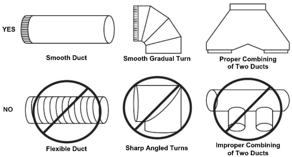
- Do not use flexible or corrugated duct. This type of duct will restrict airflow and reduce performance.
• Only use smooth, galvanized, metal duct.
• Make the duct run as short and as straight as possible with as few turns as possible.
- Avoid sharp-angled turns. Instead, use smooth, gradual turns such as adjustable elbows or 45 degree angled turns.
- For duct runs over 20 feet, increase the duct diameter by one inch for every ten feet of duct.
• A 90 degree elbow is equal to 5 feet of duct.
Termination Requirements
• Airflow must not be restricted at the end of the duct run.
• A wall louver or roof jack is required for each duct run.
• Every wall louver or roof jack must include a gravity damper to prevent back drafts.
- Do not use screen wire or spring-loaded doors on wall louvers or roof jacks.
- Do not terminate venting into an attic or chimney.
VentA Hood® Installation Details
1) Read all instructions thoroughly before beginning installation.
2) When installing a JDH/C3 wall mount range hood, it is recommended that the bottom edge of the hood be located no more than 30" above the cooking surface for optimum performance.
natural_image
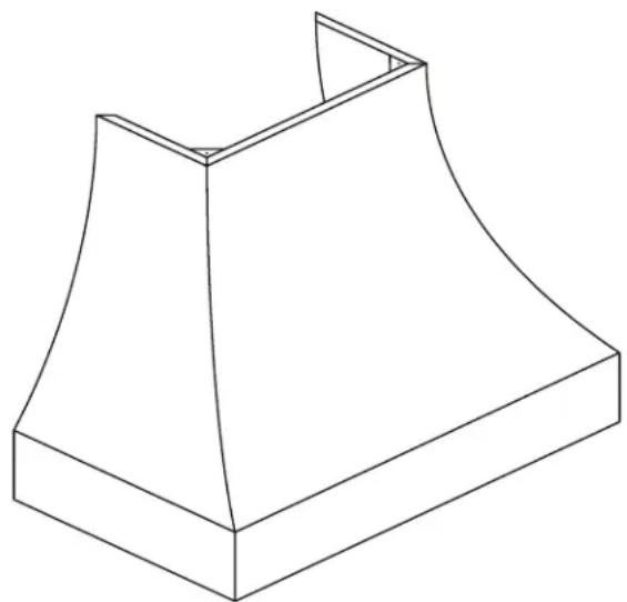
Line drawing of a 3D isometric coat hood (no text or symbols)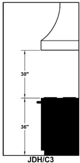
3) IF THE HOOD IS TO BE "BACK VENTED", PROCEED DIRECTLY TO STEP 4.
Install the duct from the outside of the home down to the location of the exhaust outlet on the top of the hood allowing room for the transition (if applicable). If a transition is used, install duct down to the location of the transition outlet plus 1". This will allow the transition to engage 1" inside of duct. Consult the connection diagrams (on next page) for further details on exhaust outlet placement.
Use duct tape to seal all joints. A complete listing of available Vent-A-Hood ducting materials is provided on the back page of this instruction sheet.
Transition heights are as follows:
Single Blower (B100): 6" round duct will connect directly to the top of the hood.
Dual Blower (B200): 8" round duct will connect directly to the top of the hood.
Single and Dual Blower (B100 & B200): 10" round combination transition (VP562, included) is 17 1/2 tall.
Two Dual Blowers (Two B200s): 12" round combination transition (VP563, included) is 16 1/2" tall.
4) Remove the hood from its packaging and place the back of the hood on the floor or countertop in front of the wall where it will hang.
VentA Hood®
Installation Details Continued
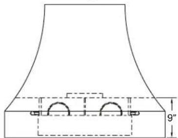
Connection Diagram (36" - 48" Widths)
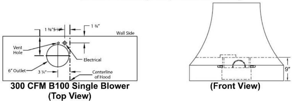
Connection Diagram (36" - 48" Widths)
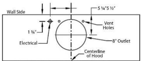
600 CFM B200 Dual Blower
(Top View)
natural_image
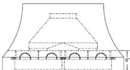
Technical line drawing of a conical-shaped component with internal features and a 9-inch height dimension (no text or symbols)(Front View)
Connection Diagram (48"-60" Widths)
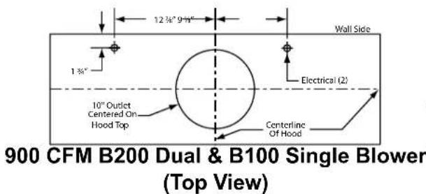
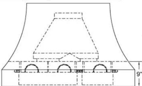
natural_image
Technical line drawing of a mechanical component with internal features and dimension label (9")VP562 Standard Transition Installed (Front View)
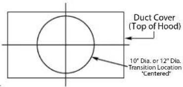
The transition shown (VP562)
is installed in the hood at the
factory as a standard item.
It will be located in the exact center of the duct cover (left to right & front to rear).
Connection Diagram (54"-66" Widths)
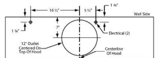
1200 CFM Double B200 Dual Blowers
(Top View)
natural_image
Technical diagram of a mechanical component with internal channels and mounting holes (no text or symbols)VP563 Standard Transition
Installed (Front View)
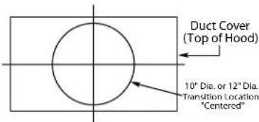
The transition shown (VP563)
is installed in the hood at the factory as a standard item. It
will be located in the exact
center of the duct cover (left to
right & front to rear).
VentA Hood®
Installation Details Continued
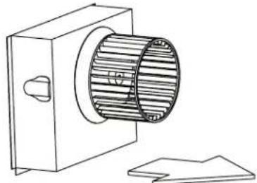
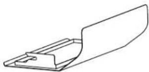
5) Remove the shipping tape that is securing the E-Z Clean shield(s) inside the hood. Remove the E-Z Clean shield(s) by lightly pulling it toward the front of the hood. Gently close the back draft damper(s) from the top side of the hood. To remove the blower housing(s), unsnap the suitcase latches (one on each side of the housing). The housing(s) should be pulled forward and gently "tipped" to clear the blower wheel(s) and then out of the hood.
natural_image
Technical line drawing of a mechanical component with a cylindrical shaft and flange (no text or symbols)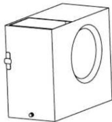
natural_image
Simple line drawing of a rectangular box with a circular vent and mounting holes (no text or symbols)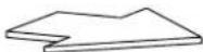
natural_image
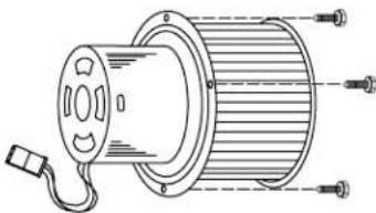
Technical line drawing of a mechanical bracket or bracket (no text or symbols)6) Remove the three screws retaining the blower motor(s). Unplug and remove the motor(s), taking care not to damage the blower wheel(s). It is not necessary to remove the blower wheel from the motor.
natural_image
Technical line drawing of a cylindrical mechanical component with mounting holes and a cable (no text or symbols)Warning: Make sure power is off and locked at the service disconnecting means on the service panel during installation.
7) Install an appropriate 1/2" UL listed electrical wire clamp through each motor box electrical opening on top of the hood. Install electrical wiring from the service panel to the hood location for each motor box. Consult the connection diagrams (on previous page) for further details on electrical placement. Extend wire(s) to the hood. Electrical connection(s) will occur before the hood is installed on the wall.
| Model Volts Amps | Hz RPM | CFM SP@0.0" | Equivalent CFM* | CFM SP@0.1" | CFM SP@0.2" | CFM SP@0.3" | Minimum Round Duct Size | Sones# | |||
| B100 Single | 115 | 2.5 | 60 | 1550 | 300 | 450 | 273 | 245 | 225 | 6" (28 in. ^2 ) | 5.4 |
| B200 Dual | 115 | 4.0 | 60 | 1550 | 600 | 900 | 531 | 480 | 430 | 8" (50 in. ^2 ) | 6.5 |
| B200 Dual & B100 Single | 115 | 6.0 | 60 | 1550 | 900 | 1350 | 804 | 725 | 655 | 10" (79 in. ^2 ) | 6.3 |
| Two B200 Duals | 115 | 7.5 | 60 | 1550 | 1200 | 1800 | 1062 | 960 | 860 | 12" (113 in. ^2 ) | 6.6 |
Because the Magic Lung® blower uses centrifugal filtration rather than conventional baffle or mesh filters, the Magic Lung® blower can handle cooking equipment with higher cubic feet per minute (CFM) requirements and can deliver equivalent CFM much more efficiently than other filtration systems. When comparing the Magic Lung® with other blower units made by other manufacturers, use the "Equivalent CFM". Ratings in accordance with the Standard Test Code by the Energy Systems Laboratory of the Texas Engineering Experiment Station.
8) If using a duct cover, remove the duct cover from its packaging and remove the mounting screws from the base of the duct cover. Place the duct cover on the top of the hood and secure it through the knockout openings using the mounting screws previously removed.
Lift the hood or the hood and duct cover assembly to the location on the wall where it will be installed. Lightly mark the wall with a short, horizontal mark along the bottom edge of the hood. When finished, remove the hood or hood and duct cover assembly from the wall. If applicable, leave the duct cover installed on the hood.
9) Remove the hood from the wall. On the back side of the hood, measure the distance between the bottom edge of the hood and the top edge of the wood mounting strip. Measure this distance above the horizontal line made in Step 8 and lightly mark the wall with a level, horizontal line. Measure where the center (left to right) of the hood will be and mark the upper, horizontal line on the wall with a short, vertical centerline.
10) Remove the screws inside the top of the back of the hood that retain the wood strip that is recessed in the mounting channel. Note: Some retaining screws may be located behind the blower(s). Remove the wood mounting strip from the back of the hood and place the top edge of the strip on the upper, level horizontal line on the wall. Referencing the vertical centerline from Step 9, place the mounting strip on the wall so it is centered (left to right) in the space where the hood will be located. Drill pilot holes in the strip to prevent splitting. Using proper hardware, attach the mounting strip to at least two wall studs.
VentA Hood®
Installation Details Continued
11) FOR BACK VENTING APPLICATIONS ONLY. IF NOT BACK VENTING, PROCEED DIRECTLY TO STEP 12.
Note: Wall studs may interfere with back venting installations. Additional framing may be required. It is necessary to cut a duct access hole in the wall prior to installing the hood.
To accomplish this, first remove and set aside any duct cover that was previously installed in Step 8. Hold the hood on the mounting strip by aligning the channel at the top of the back of the hood over the wood mounting strip on the wall. Place the appropriate elbow on top of the hood in line with the hood exhaust collar. On the wall, trace around the elbow. Remove the hood and elbow from the wall. Cut around the outside of the traced line, avoiding wall studs. Install the duct from the outside of the home to the opening in the wall. Use duct tape to seal joints. If applicable, place the duct cover back onto the top of the hood and reattach it to the hood.
12) Hang the hood on the mounting strip by aligning the channel at the top of the back of the hood over the wood mounting strip on the wall. While holding the hood in place, mark locations on the mounting strip through the two mounting holes in the channel at the top of the hood. Some mounting holes may be located behind the blower(s). Remove hood and drill 3/32" pilot holes at the center of marks in the wood strip to prevent splitting.
13) FOR BACK VENTING APPLICATIONS ONLY. IF NOT BACK VENTING, PROCEED DIRECTLY TO STEP 14.
Place the appropriate elbow on the top of the hood. The elbow should be placed with the non-crimped end on the inside the collar of the exhaust outlet. Use duct tape to seal joint. Insert the electrical wire(s) from the service panel into the electrical wire clamp on each motor box. Tighten the wire clamp(s). While securing the slack in the wire(s), lift the hood (and duct cover) up to the wall and hang the hood on the mounting strip, taking care to properly align the duct connection between the elbow on the hood and the duct in wall. Secure the hood to the mounting strip by installing the screws (previously removed in Step 10) into the pilot holes drilled in Step 12. SKIP STEPS 14 AND 15. PROCEED DIRECTLY TO STEP 16.
14) Insert the electrical wire from the service panel into the electrical wire clamp on each motor box. Tighten the wire clamp(s). Cut a piece of duct of sufficient length to meet the duct in the ceiling allowing room for the transition (if applicable). If a transition is used, cut the duct to reach the transition outlet plus 1". This will allow the transition to engage 1" inside of the duct. See Page 3 for transition heights. One end of the duct must be crimped to fit inside the duct in the ceiling. Insert the non-crimped end over the transition or into the exhaust collar on the top of the hood and seal with duct tape.
15) While securing the slack in the wire(s), lift the hood (and duct cover) up to the wall and hang the hood on the mounting strip, taking care to properly align the duct connection between the hood and the duct in the ceiling. Secure the hood to the mounting strip by installing the screws (previously removed in Step 10) into the pilot holes drilled in Step 12.
16) From inside the hood, using UL listed wire nuts, attach the "neutral" wire(s) to the white lead(s), the "hot" wire(s) to the black lead(s), and the ground wire(s) to the green lead(s) inside the motor box(es).
Warning: Do not operate hood without proper ground connection.
17) Plug the motor(s) into the hood and reinstall the blower motor(s) using the three retaining screws that were previously removed in Step 6.
18) Replace the blower housing(s) and the E-Z Clean shield(s). Make sure that the damper(s) open and close smoothly.
19) Refer to the Owner Maintenance Guide Operating Instructions for proper hood operation. Test all blower and light functions to ensure they are operating properly.
VENTINGACCESSENT AHAOD®
WALL LOUVER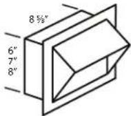 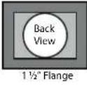 MODEL DIMVP526 6" RoundVP527 7" RoundVP528 8" Round MODEL DIMVP526 6" RoundVP527 7" RoundVP528 8" Round | WALL LOUVER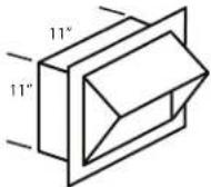 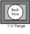 MODEL DIMVP554 10" Round MODEL DIMVP554 10" Round | WALL LOUVER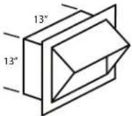 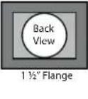 MODEL DIMVP555 12" Round MODEL DIMVP555 12" Round | RECTANGULAR WALL LOUVER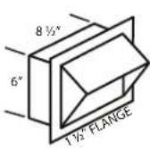 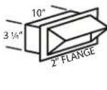 MODEL DIMVP538 6" x 8 1⁄2"VP560 3 1⁄4" x 10" MODEL DIMVP538 6" x 8 1⁄2"VP560 3 1⁄4" x 10" |
LOW PROFILE ROOF JACK(MAXIMUM 4/12 PITCH)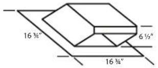 MODEL DIMVP539 6" RoundVP540 7" RoundVP541 8" Round MODEL DIMVP539 6" RoundVP540 7" RoundVP541 8" Round | LOW PROFILE ROOF JACK(MAXIMUM 4/12 PITCH)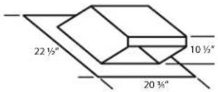 MODEL DIMVP552 10" RoundVP553 12" Round MODEL DIMVP552 10" RoundVP553 12" Round | LOW PROFILE ROOF JACK(MINIMUM 4/12 PITCH)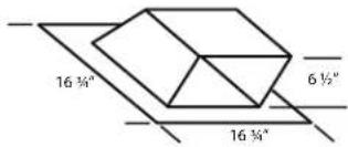 MODEL DIMVP539-HP 6" RoundVP540-HP 7" RoundVP541-HP 8" Round MODEL DIMVP539-HP 6" RoundVP540-HP 7" RoundVP541-HP 8" Round | LOW PROFILE ROOF JACK(MINIMUM 4/12 PITCH)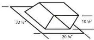 MODEL DIMVP552-HP 10" RoundVP553-HP 12" Round MODEL DIMVP552-HP 10" RoundVP553-HP 12" Round |
ADJUSTABLE ELBOW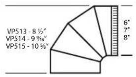 MODEL DIMVP513 6" RoundVP514 7" RoundVP515 8" Round MODEL DIMVP513 6" RoundVP514 7" RoundVP515 8" Round | BACK/SIDE VENT ELBOW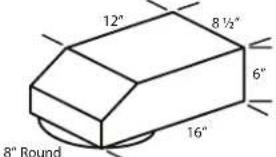 MODEL DIMVP561 8" to 6" x 8 1⁄2" MODEL DIMVP561 8" to 6" x 8 1⁄2" | 3 1⁄4" x 10" BACK VENT ELBOW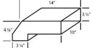 MODEL DIMVP559 3 1⁄4" x 10" MODEL DIMVP559 3 1⁄4" x 10" | 3 1⁄4" x 10" TO 7" TRANSITION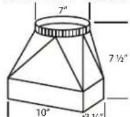 MODEL DIMVP521 3 1⁄4" x 10" to 7" MODEL DIMVP521 3 1⁄4" x 10" to 7" |
MULTI-BLOWER TRANSITION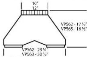 MODEL DIMVP562 6" & 8" to 10"VP563 8" & 8" to 12" MODEL DIMVP562 6" & 8" to 10"VP563 8" & 8" to 12" | M1200 STANDARD TRANSITION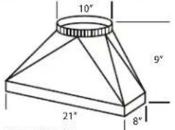 MODEL DIMVP566 21" x 8" to 10" MODEL DIMVP566 21" x 8" to 10" | STANDARD ISLAND TRANSITION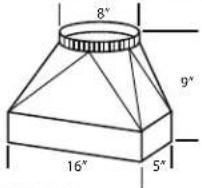 MODEL DIMVP565 5" x 16" to 8" MODEL DIMVP565 5" x 16" to 8" | CLUSTER BLOWER TRANSITION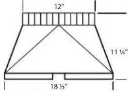 MODEL DIMVP564 8" & 8" to 12" MODEL DIMVP564 8" & 8" to 12" |
OFFSET L & R TRANSITIONFOR ISI AND BI OWERS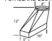 MODEL DIMVP542 Top LeftVP543 Top Right MODEL DIMVP542 Top LeftVP543 Top Right | SIDE VENT TRANSITION L & RFOR ISI AND BI OWERS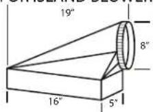 MODEL DIMVP544 Left SideVP545 Right Side MODEL DIMVP544 Left SideVP545 Right Side | OFFSET KIT - ROUND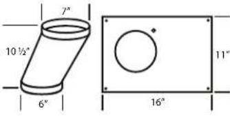 MODEL DIMVP529 6" Rnd to 7" Rnd MODEL DIMVP529 6" Rnd to 7" Rnd | OFFSET KIT - RECTANGULAR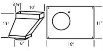 MODEL DIMVP550 6" Rnd to 3 1⁄4" x 10" MODEL DIMVP550 6" Rnd to 3 1⁄4" x 10" |
"Y" TRANSITION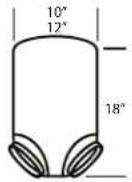 MODEL DIMVP517 8" & 8" to 12"VP518 6" & 8" to 12"VP551 6" & 8" to 10" MODEL DIMVP517 8" & 8" to 12"VP518 6" & 8" to 12"VP551 6" & 8" to 10" | ROUND DUCT PIPE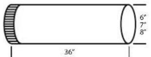 MODEL DIMVP500 6" RoundVP501 7" RoundVP502 8" Round MODEL DIMVP500 6" RoundVP501 7" RoundVP502 8" Round | 3 1⁄4" RECTANGULAR DUCT PIPE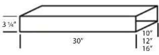 MODEL DIMVP504 3 1⁄4" x 10"VP505 3 1⁄4" x 12"VP506 3 1⁄4" x 16" MODEL DIMVP504 3 1⁄4" x 10"VP505 3 1⁄4" x 12"VP506 3 1⁄4" x 16" | 6" RECTANGULAR DUCT PIPE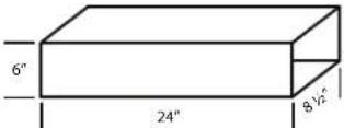 MODEL DIMVP507 6" x 8 1⁄2" MODEL DIMVP507 6" x 8 1⁄2" |
- Read and Save These Instructions
- INSTALLATION INSTRUCTIONS
- JDH/C3 DESIGNER SERIES
- WALL MOUNT HOOD
- VentA Hood®
- Ducting Do's and Don'ts
- General Requirements
- Blower Requirements
- Ducting Requirements
- Termination Requirements
- VentA Hood® Installation Details
- Installation Details Continued
- Warning: Make sure power is off and locked at the service disconnecting means on the service panel during installation.
- VENTINGACCESSENT AHAOD®
Brand : Vent-A-Hood
Model : JDH236C3SS
Category : Range hood