
HD9813RK - Loudspeaker Rockford Fosgate - Free user manual and instructions
Find the device manual for free HD9813RK Rockford Fosgate in PDF.

| Product Type | Speaker Kit (Saddlebag Lid) |
| Brand | Rockford Fosgate |
| Model | HD9813RK (TMS69) |
| Application | Harley-Davidson® 1998-2013 with Factory Saddlebags |
| Nominal Diameter | 6 x 9 in (152 x 229 mm) |
| Speaker Type | 2-Way |
| Impedance | 4 Ohms |
| Frequency Response | 56 Hz - 20 kHz |
| Power Handling (RMS/Peak) | 100 W / 200 W |
| Sensitivity (1W/1M) | 89 dB |
| Sensitivity (2.83V/1M) | 92 dB |
| Voice Coil Diameter | 1.4 in (35.6 mm) |
| Fs (Free Air Resonance) | 75 Hz |
| Qts | 1.63 |
| Vas | 0.593 cu ft (16.8 L) |
| Xmax | 0.12 in (3 mm) |
| Mounting Diameter | 8.7 x 5.8 in (218 x 147 mm) |
| Mounting Depth | 2.8 in (71 mm) |
| Grille Included | Yes (2 grilles) |
| Contents | 2 speakers, 2 grilles, 2 mounting rings, 2 templates, 16 screws, main harness, saddlebag harnesses, zip ties, cable mounts |
| Warranty | 2 years (motorcycle products) |
| Safety | Disconnect battery negative terminal before installation |
Frequently Asked Questions - HD9813RK Rockford Fosgate
User questions about HD9813RK Rockford Fosgate
0 question about this device. Answer the ones you know or ask your own.
Ask a new question about this device
Download the instructions for your Loudspeaker in PDF format for free! Find your manual HD9813RK - Rockford Fosgate and take your electronic device back in hand. On this page are published all the documents necessary for the use of your device. HD9813RK by Rockford Fosgate.
USER MANUAL HD9813RK Rockford Fosgate
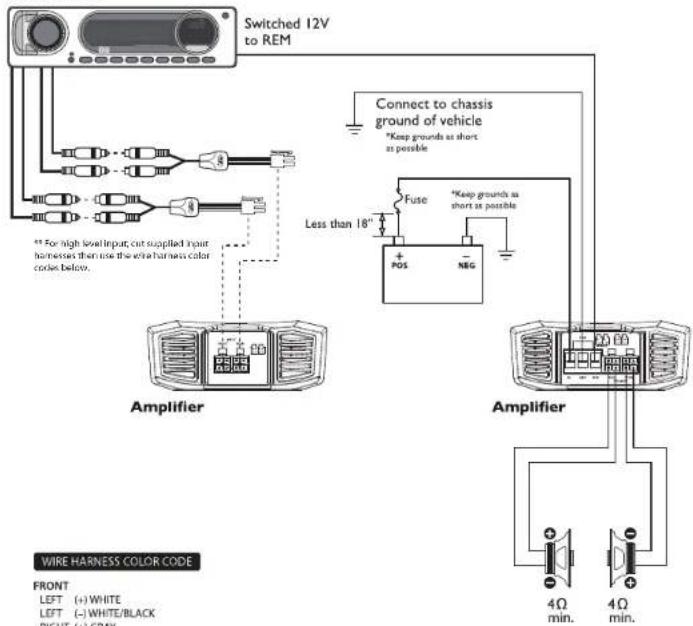
Amplifier Quick Setup
CAUTION
Be sure to connect speakers and Punch Level Control - PLC (if equipped) after amplifier output clip adjustment. (see reverse)
* Specifications subject to change without notice. Images depict typical setup. Refer to manual for additional wiring options.
WIRE HARNESS COLOR CODE

Rockford Fosgate
Step 1 - Input
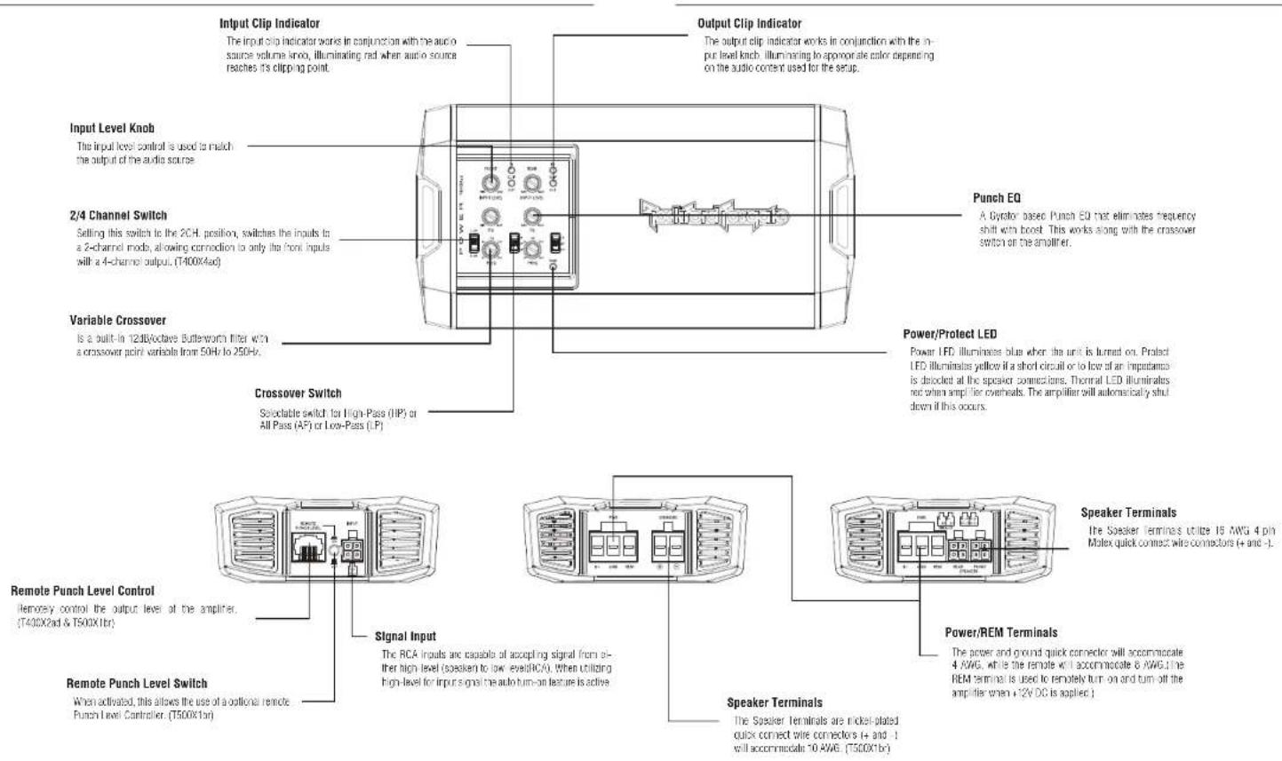
Input Clip Indicator Setup
Be sure to disconnect all speakers from the amplifier.

CAUTION
Failure to comply may cause damage to connected components and/or amplifier.

Step 2 - Input
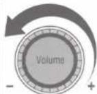
Turn on the source unit with volume set to zero.


Step 3 - Input
Adjust the Bass & Treble levels on the source unit to flat.

Amplifier Clip Indicator Setup
Step 4 - Input
Insert test tone or music CD to play for setup.

Note: Use the 40Hz @ 0dB tone (Track 5) for mono amplifier applications or the 1kHz @ 0dB tone (Track 7) for multi-channel amplifier applications. Be sure your x-over is switched to the appropriate filter setting.
Step 5 - Input


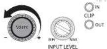
Increase the source unit volume until the Input Clip Indicator illuminates red.
Note: Input Clip can be viewed remotely with optional PLC2.
Step 6 - Input
Decrease the source unit volume slightly until the light turns completely off. This establishes your maximum source unit volume for adjusting the Output Clip Indicator.
Note: Some source units will not clip.
Step 7 - Output
Be sure to disconnect Punch Level Control - PLC (if equipped) from the amplifier.
Step 8 - Output
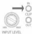
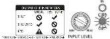
Output Clip Indicator Setup

Adjust the Input Level knob until the Output Clip Indicator illuminates to the appropriate color. Repeat for all channel levels of input.
Step 9 - Output
Turn the source unit volume down.
Step 10 - Output
Reconnect all speakers and Punch Level Control - PLC (if equipped) to the amplifier. Be sure to maintain proper speaker polarity.


Rockford Fosgate
POWER

T400X2ad • T400X4ad
T500X1br
Introduction
Specifications
Dear Customer.
Congratulations on your purchase of the world's finest brand of car audio products. At Rockford Fesgate we are fanatics about musical reproduction at its best, and we are pleased you choose our product. Through years of engineering expertise, hand craftsmanship and critical testing procedures, we have created a wide range of products that reproduce music with all the clarity and richness you deserve.
For maximum performance we recommend you have your new Rockford Fosgate product installed by an Authorized Rockford Fosgate Dealer, as we provide specialized training through Rockford Technical Training Institute (RTTI). Please read your warranty and retain your receipt and original carton for possible future use.
Great product and competent installations are only a piece of the puzzle when it comes to your system. Make sure that your installer is using 100% authentic installation accessories from Rockford Fosgate in your installation. Rockford Fosgate has everything from RCA cables and speaker wire to power wire and battery connectors. Insist on it. After all, your new system deserves nothing but the best.
To add the finishing touch to your new Rockford Fosgate image order your Rockford accessories, which include everything from T-shirts to jackets.
Visit our web site for the latest information on all Rockford products: www.rockfordfospale.com
or, in the U.S. call 1-800-669-9899 or FAX 1-800-398-3985. For all other countries, call +001-480-967-2665 or FAX +001-480-966-3983.
Table of Content
2 Introduction
3 Specifications
4-5 Design Features
6-13 Installation
Installation Considerations
Mounting Locations
Battery and Charging
Wiring the System
14-15 Operation
Clip Indicator Setup
Adjusting Crossover Frequency
2/4 Channel Switch
Punch EQ
16 Troubleshooting
17 Limited Warranty Information
If, after reading your manual, you still have questions regarding this product, we recommend that you see your Rosford Icsgate dealer. If you need further assistance, you can call us direct at 1-800-669-9899. Be sure to have your serial number, model number and date of purchase available when you call.
PRACTICE SAFE SOUND
Continuous exposure to sound pressure levels over 100dB may cause permanent hearing loss. High powered auto sound systems may produce sound pressure levels well over 130dB, use common sense and practice safe sound.
Safely
This symbol with "WARNING" is intended to alert the user to the presence of important instructions. Failure to head the instructions will result in severe injury or death.

This symbol with "CAUTION" is intended to alert the user to the presence of important instructions. Failure to head the instructions can result in injury or unit damage.
- To prevent injury and damage to the unit, please read and follow the instructions in this manual. We want you to enjoy this system, not gel a headache.
- If you feel unsure about installing this system yourself, have it installed by a qualified Rockford Fosgate technician.
- Before installation, disconnect the battery negative (-) terminal to prevent damage to the unit, fire and/or possible injury.
Mode T400X2ad T400X4ad T500X1br
| Rated PowerContinuous PowerRating (MHz)/Measured dB*<10Crossover Stage | 200Hz @ 4.5nm200Hz @ 2.7cm400x1.8x4.0m3 | 100Hz @ 4.5nm100Hz @ 2.7cm200Hz @ 4.0m3 | 175x1.8x4.0cm300x1.8x2.7cm500x1.8x1.6cm |
| 2 dB/Oct 12 dB/Oct 12 dB/Ccl | |||
| Frequency Response | Variable 5GHz, 250Hz Variable 50Hz, 250Hz Variable | ||
| Power I/O | Volume 0 ~ 14dB CF12.5kHz and 0 ~ 18dB CF 45Hz | Volume 0 ~ 14dB CF12.5kHz and 0 ~ 19dB CF 45Hz | Volume 0 ~ 16dB CF45Hz |
| Operating Voltage | 9-10VDC 9-10VDC 9-10VDC | ||
| Frequency Response | 20 x~23dB CF 20x~20x x 70 x~250 x 7 | ||
| Battery Type Rating(not supplied) | 50% 50% 60A | ||
| THO+V® FaultPower | <1.0% @ 4.5cm<1.0% @ 2.5cm | <1.0% @ 4.5cm<1.0% @ 2.5cm | <1.3% @ 4.5cm<1.3% @ 2.5cm<1.3% @ 1.5cm |
| Input Security | 150mV~12V 150mV~12V Low Isomv~5V | High 30cmV~12V | |
| Input Impedance | 20x 20x 20x | ||
| S/N Ratio CEA 200S | >60dB >90dB >40dB | ||
| S/N Ratio / FaultPower | >110dB >110dB >110dB | ||
| Channel Separation | >60dB >90dB N/A | ||
| Common ModeFunction Ratio | >90dB >60dB >40dB | ||
| Dimensions (L×W/d) | " × 4.3" × 1.6"100mm X=1cm | 8.3"×4.3" × 1.6"2.5mm X=1cm | 8.3"×4.3" × 1.6"100mm X=1cm |
* Fated power when amplifier is wired in a bridged configuration.
©2014 Rockford Corporation. All Rights Reserved. FORCKFORD FOSGATE and associated boxes where applicable are registered trademarks of Rockford Corporation in the United States and/or other countries. All other trademarks are the property of their respective owners. Specifications subject to change without notice.

CEA 2006
Power ratings on Hotspot Large amplifiers conform to 316-2006 industry standards. These guidelines make your amplifier's output power ratings on REAL POWER members out inhaled marketing rates.
Installation Installation
Contents
• Power Appliance
• HCA to 4-pin Molex Input
Connectors
• 15 AWS 4-oin Melex SASKER
Connector(s) (1400X2ad &
T4004-60
• 10 AWG Speaker Connector
(T500)X1B
Installation Considerations
The following is a list of tools needed for installation:
- Fuse-holder and fuse. (See
specifications for issue rating)
• 160-375mm 1.4m/s
- Wire stippers
• Wire crimpers
• Wire cutters
• #2 Phillips screwdriver
- Battery post wrench
This section focuses on some of the vehicle considerations for installing your new snolther. Pre-planning your system layout and best wiring routes will save installation time. When deciding on the layout of your new system, be sure that each component will be easily accessible for making adjustments.

CAUTION
[Non-Text]
If you feel unsure about installing this sys-
temyourself,haveit insta eobyacquallied
technician

CAUTION
Before installation, disconnect the battery reg
alive (-) terminal to prevent damage to the unit.
fire and/or possible injury.
Before beginning any installation, follow these simple rules:
- Be sure to carefully read and understand the instructions before attempting to install the unit.
2 For safety, disconnect the negative lead from the battery prior to beginning the installation. - For easier assembly, we suggest you run all wires prior to mounting your unit in place.
- Route all of the RCA cables close together and away from any high current wires.
-
Use high quality connectors for a reliable installation and to minimize signal or power loss.
-
Think before you drill Be careful not to cut or drill into gas tanks, fuel lines, brake or hydraulic lines, vacuum lines or electrical wiring when working on any vehicle
- Never run wires underneath the vehicle. Running the wires inside the vehicle provides the best protection.
- Avoid running wires over or through sharp edges. Use rubber or plastic grommets to protect any wires routed through metal, especially the firewall.
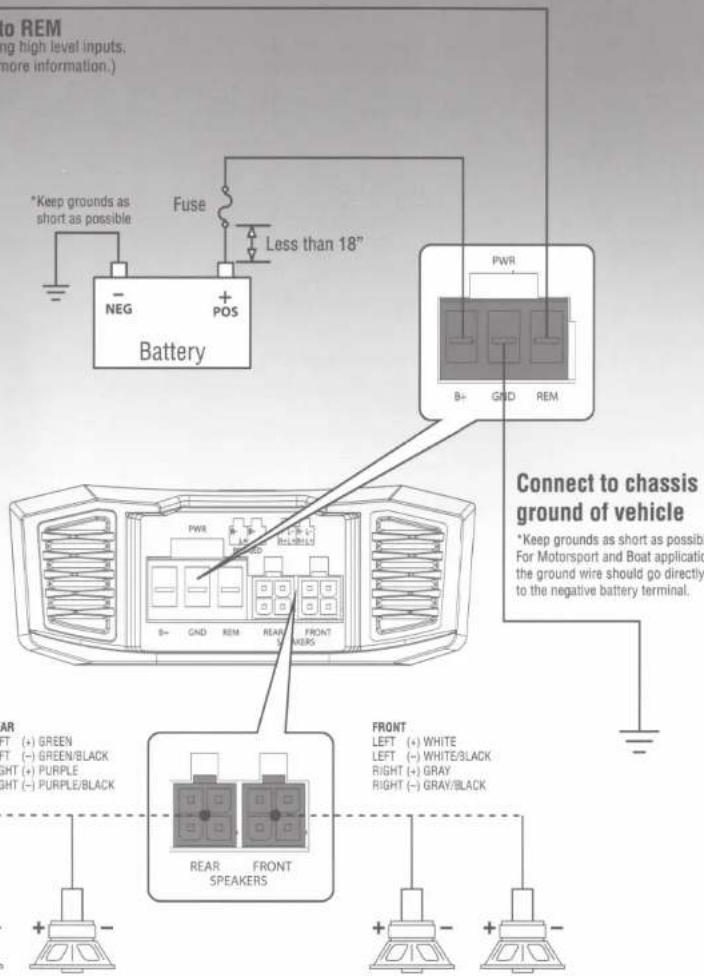
9 ALWAYS protect the battery and electrical system from damage with proper fusing. Install the appropriate fuse holder and fuse on the -12V power wire within 18" (45.7 cm) of the battery terminal. - When grounding to the chassis of the vehicle, scrape all paint from the metal is unsure a good, clear ground connection. Grounding connections should be as short as possible and always be connected to metal that is welded to the main body, or chassis of the vehicle. Sealball balls should never be used for connecting to ground.
Mounting Locations
To ensure optimal performance, record the amplifier with at cas, 1° (2.54cm) of air gap around the amplifier's heat sink to provide proper cooling.
Trunk Mounting
Mounting the amplifier vertically or inverted will provide adequate cooling of the amplifier. Mounting the amplifier on the floor of the trunk will provide the best cooling of the amplifier.
Passenger Compartment Mounting
Mounting the amplifier in the passenger compartment will work as long as you provide a sufficient amount of air for the amplifier to cool itself. If you are going to mount the amplifier under the seal of the vehicle, you must have at least 1" (2.54cm) of air gap around the amplifier's heat sink.

CAUTION
Never mount this unit in the engine
compartment. Mounting the Crit in the engine
Emission will void your warranty.
ATVs, Golf Carts or Motorcycle
When using amplifiers on ATVs, Coil Carls or Motorcycles, Rockford Fos-gate recommends to run both GND (negative) and B+ (positive) cables from the amplifier directly to the battery. We have determined that bushings between frame parts cause an excessively high resistance and is not considered a good electrical ground.

This is especially true with motorcycles. DO
NOT ground the amplifier to the radio chassis.
headlamp or forks because the difference in
ground potential may cause unstable operation.

CAUTION
Be sure all ground connections are properly
terminated for optimum electrical continuity.
Battery and Charging
Amplifiers will put an increased lead on the vehicle's battery and charging system. We recommend checking your alternator and battery condition to ensure that the electrical system has enough capacity to handle the increased load of your stereo system. Stock electrical systems which are in good condition should be able to handle the extra lead of any Prime Series amplifier without problems, although battery and alternator life can be reduced slightly. To maximize the performance of your amplifier, we suggest the use of a heavy duty battery and an energy storage capacitor
Wiring the System

CAUTION
If you do not feel comfortable with wiring your new unit, please see your local Authorized Rockford Fasgate Dealer for installation

CAUTION
Before installation, discerned the battery negative 1-1 terminal to prevent damage to the unit, fire and/or possible injury.

CAUTION
Avoid running power wires near the low level input tables, anionine, power leads, sensitive equipment or harnesses. The power wires carry substantial current and could induce noise into the audio system.
- Plan the wire routing. Keep RCA cables close together but isolated from the amplifier's power cables and any high power auto accessories, especially electric motors. This is done to prevent coupling the noise from radiated electrical fields into the audio signal. When feeding the wires through the firewall or any metal barrier, protect them with plastic or rubber grammals to prevent short circuits. I leave the wire long at this point to adjust for a precise fit at a later time.
- Prepare the RED wire (power cable) for allachment to the amplifier by striping 1/2" of insulation from the end of the wire, insert the bared wire into the B+ terminal and tighten the set screw to secure the cable in place.
NOTE: The 8+ cable MUST be fused 18" or less from the vehicle's battery. Install the fuse holder under the food and ensure connections are water light. - Trim the RLD wire (power cable) within 16" of the battery and splice in a inline fuse holder (not supplied). See Specifications for the rating of the fuse to be used. DO NOT install the fuse at this time.
- Strip 1/2 from the battery and of the power cable and crimp an apooriolate size ring terminal to the cable. Use the ring terminal to connect to the battery positive terminal.
- Prepare the BLACK wire (Ground cable) for attachment to the amplifier by shipping 1/2" of insulation from the end of the wire. Insert the bare wire into the GROUND terminal and lighten the sell screw to secure the cable in place. Prepare the chassis ground by scraping any paint from the metal surface and thoroughly clearing the area of all dirt and grease. Strip the other end of the wire and attach a ring connector. Fasten the cable to the chassis using a non-anchored screw and a star washer.
NOTE: Keep the length of the BLACK wire (Ground) as short as possible. Always less than 30°.
- Prepare the Remote turn-on wire for attachment to the amplifier by stripping 1/2" of insulation from the end of the wire. Insert the bared wire into the RLMCTL terminal and tighten the set screw to secure the wire in place. Connect the other end of the Remote wire to a switched 12 volt positive source. The switched voltage is usually taken from the source unit's remote amp on load. If the surge until does not have this current available, the recommended solution is to write a mechanical switch in line with a 12 volt source to activate the amplifier.
NOTE: When utilizing high-level for input signal the auto turn-on feature is active. With the auto turn-on active, the REM becomes an output to turn on/off up to two additional amplifiers or other accessories. - Securely mount the amplifier to the vehicle or ampack. Be careful not to mount the amplifier on cardboard or plastic panels. Doing so may enable the screws to pull out from the panel due to road vibration or soccer vehicle stops.
- Connect from source signal by plugging into the RCA input jacks at the amplifier. The input sensitivity ranges from 150mV-12V to accommodate signal from either high-level(speaker) to low-level (RDA).
NOTE: All "ACTIVE" inputs must have quick connectors connected. Switch in 2CH, position, "ACTIVE" - Front channel inputs only. Switch in 4CH, position, "ACTIVE" - All Front and Rear channel inputs. Be sure to route front and rear RCA cables lightly together.

CAUTION
Always ensure power is off or disconnected at
the amplifier before connecting input cables.
Failure to do so may cause call age to the amplifier and/or connected containers.
- Connect the speakers. Strip the speaker wires 1/2" and insert into the speaker terminal and tighten the sat screw to secure into place. Be sure to maintain proper speaker polarity. DO NOT chassis ground any of the speaker leads as unstable operation may result.
- Perform a final check of the completed system wiring to ensure that all connections are accurate. Check all power and ground connections for frayed wires and loose connections which could cause problems. Install inline fuse near battery connection.
NOTE. Follow the diagrams for proper signal polarity.

CAUTION
This amplifier is not recommended for im
poblance Icains hdlw 2-John Stenck,4-OFF
Bridgler for the 10-11mmal amplifiers and 1-chm for mono amplifiers.
Installation Installation
2-Channel (Stereo) T400X2ad
Source Unit
WARNING
ATVs, Golf Carts or Motorcycle
When using amplifiers on ATVs, Golf Carts or Motorcycles, Rockford Foggate recommends to run both GND (negative) and B+ (positive) cables from the amplifier directly to the battery.
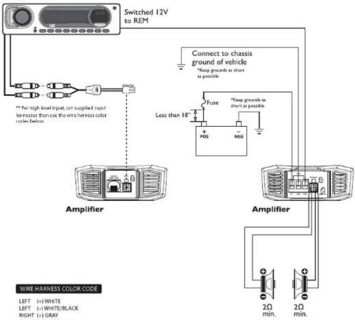
2-Channel (Mono) T400X2ad
Source Unit

WARNING
ATVs, Golf Carts or Motorcycle
When using amplifiers on ATVs, Golf Carts or Motorcycles, Rockford Fosgate recommends to run both GND (negative) and B+ (positive) cables from the amplifier directly to the battery.
(12.7)
H0.21
Installation Installation
4-Channel (Stereo)
T400X4ad
Source Unit
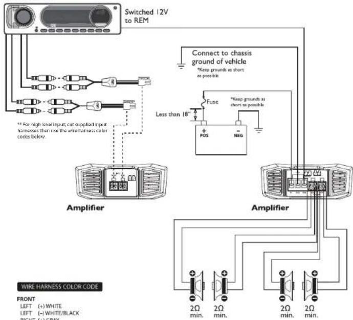
WIRE HARNESS COLOR CODE
FRONT
LEFT (+) WHITE
LEFT (-)WHITE/BLACK
RIGHT (+) GRAY
RIGHT (-) GRAY/BLACK
REAR
LEFT (+) GREEN
LEFT (-) GREEN/BLACK
RIGHT (+) PURPLE
RIGHT (-) PURPLE/BLACK
WARNING
ATVs, Golf Carts or Motorcycle
When using amplifiers on ATVs, Golf Carts or Motorcycles, Rockford Fosgate recommends to run both GND (negative) and B+ (positive) cables from the amplifier directly to the battery.
4-Channel (2ch Stereo & 1ch Mono-Bridged)
T400X4ad
Source Unit
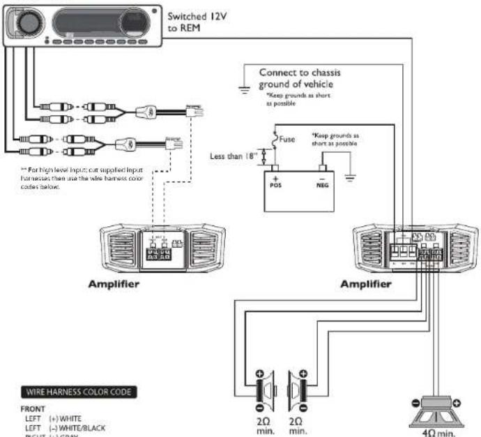
WIRE HARNESS COLOR CODE
FRONT
LEFT (+)WHITE
LEFT (-) WHITE/BLACK
RIGHT (+) GRAY
RIGH
REAR
LEFT (+) GREEN
LEFT (-) GREEN/BLACK
RIGHT (+) PURPLE
RIGHT (-) PURPLE/BLACK
WARNING
ATVs, Golf Carts or Motorcycle
When using amplifiers on ATVs, Golf Carts or Motorcycles, Rockford Fosgate recommends to run both GND (negative) and B+ (positive) cables from the amplifier directly to the battery.
1.2010.24
Installation
Installation
4-Channel (2ch Mono-Bridged) T400X4ad
Source Unit
WIRE HARNESS COLOR CODE
FRONT
LEFT (+) WHITE
LEFT (-)WHITE/BLACK
RIGHT (+) GRAY
RIGHT (-) GRAY/BLACK
REAR
LEFT (+) GREEN
LEFT (-) GREEN/BLACK
RIGHT (+) PURPLE
RIGHT (-) PURPLE/BLACK
WARNING
ATVs, Golf Carts or Motorcycle
When using amplifiers on ATVs, Golf Carts or Motorcycles, Rockford Fosgate recommends to run both GND (negative) and B+ (positive) cables from the amplifier directly to the battery.
Mono Wiring T500X1br
Source Unit

WARNING
ATVs, Golf Carts or Motorcycle
When using amplifiers on ATVs, Golf Carts or Motorcycles, Rockford Fosgate recommends to run both GND (negative) and B+ (positive) cables from the amplifier directly to the battery.
11.73
2
10.75
13
Input Clip Indicator Setup
Step 1. Be sure to disconnect all speakers from the amplifier.


CAUTION
Failure to comply may cause damage to con- ncled components and/or amplifier.
Step 2. Turn on the source unit with volume set to zero
Step 3. Adjust the Bass & Treble levels on the source unit to flat.
Step 4. Insert test tone or music CD to play for setup.
Note: Use the 40Hz @ CdB tone (Track 5) for mono amplifier applications on the 1kHz @ CdB tone (Track 7) for multi-channel amplifier applications. Be sure your x-over is switched to the appropriate filter setting.
Step 5. Increase the source unit volume until the input Clip Indicator if luminates red.

Note: Input Cip can be viewed remotely with optional PLC2.
Sep 6. Decrease the source unit volume slightly until the light turns completely off. This establishes your maximum source unit volume for adjusting the Cutgul Clip Indicator
Note: Some source units will not ciba.
Output Clip Indicator Setup
Step 7. Be sure to disconnect Punch Level Control - PLC (if equipped) from the amplifier.
Step 8. Adjust the Input Level knob until the Output Clip Indicator Illuminates to the appropriate color. Repeat for all channel levels of Input.
Step 3. Turn the source unit volume down
Step 10. Reconnect all speakers and Punch Level Control PLC (in equipped) to the amoliter. Be sure to maintain proper speaker polarity.

Adjusting Crossover Frequency
Do the following individually for each channel.
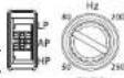
Placing the crossover switch in the HP position sets the amplifier to the High Pass mode, enabling frequencies above the cut-off point to pass, adjustable between 50-250Hz.
Placing the crossover switch in the AP position sets the amplifier to the All Pass mode, preventing any crossover adjustment, allowing all frequencies to pass.
Placing the crossover switch in the LP position sets the amplifier to the Low Pass mode, enabling frequencies below the cut-off point to pass, adjustable between 50-250 Hz.
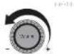
Turn the crossover adjustment knob all the way down. With the system playing, turn the crossover adjustment knob up slowly until the desired crossover point is achieved.
2/4 Channel Switch
Setting this switch to the 2CH position, switches the inputs in a 2-channel mode, allowing connection to only the front inputs with a 4-channel output.
Circuit controls function the same as if the amplifier was in 4-channel mode.
All "ACTIVE" inputs must have RCA jacks connected. Switch in 2CH. position, "ACTIVE" - Front channel inputs only Switch in 4CH. position, "ACTIVE" - All Front and Rear channel inputs
NOTE: When connecting to the 4-Channel inputs, be sure to route both front and rear RCA cables tightly together.
High Level Input
Connect from source signal by plugging into the RCA input jacks at the amplifier. The input sensitivity ranges from 150mV-12V to accommodate signal from high-level (speaker) input. When utilizing high-level for input signal the auto turn-on feature is active. With the auto turn-on active, the REM becomes an output to turn on/off up to two additional amplifiers or other accessories.
Punch EQ
This works along with the crossover switch on the amplifier. When set to Low-Pass (LP) operation, this is a variable Bass Boost. When set to High-Pass (HP) operation, this is a variable Mild Bass and Treble Boost. When set to All-Pass (AP) operation, both the Bass and Treble frequencies are boosted. Set this to your personal preference while listening to the system.

CAUTION Over excursion and subsequent damage may occur at high levels of boost.
Remote Punch Level Control (Option)
NOTE: Previous(prior to 2013)PEG PunchBassardPare-Punch remedies will not work with these amplifiers.
Quick Install:
-
Using the screws supplied, install the mounting clip.
-
Slip the remote onto the mounting clip until it snaps into place.
-
Route and connect the cable to the remote and amplifier.
Operation:
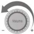
- When connected, the "Subwoofer Level Control" is linked and allows you to remotely control the output level of the amplifier from the dash or center console.
For the T500X1br, the Female Punch Level Control needs to be switched to the "ON" position for this feature to be active. The T400X2ad needs to be switched in "Low-Pass" for this feature to be active. This feature is not available on the T400X4ad.
NOTE: Use the instructions that came with the remote for a variety of mountings that fit your preference.
Troubleshooting
NOTE: If you are having problems after installation follow the Troubleshooting procedures below.
Check Amplifier for proper connections. Verify that POWER light is on. If POWER light is on skip to Step 3, if not continue.
- Check In-line fuse on battery positive cable. Replace it necessary.
- Check fuse(s) on amplifier. Replace it necessary.
- Verify that Ground connection is connected to clean metal on the vehicle's chassis. Repair/replace if necessary.
- Verify there is 9 to 14.4 volts present at the positive battery and remote turn-on cable. Verify quality connections for both cables at amplifier, stereo, and battery/use holder. Repair/replace if necessary. Protect light is on.
- If the Protect light is on, this is a sign of a possible short in the speaker connections. Check for proper speaker connections and use a volt/ohm meter to check for possible shorts in the speaker wiring. Too low of a speaker impedance may also cause Protect to light.
Check Amplifier for audio output.
- Verify good RCA input connections at stereo and amplifier. Check entire length of cables for kinks, splices, etc. Test RCA inputs for AC volts with stereo on. Repair/replace if necessary.
- Disconnect RCA input from amplifier. Connect RCA input from test slano directly to amplifier input
Check Amplifier if you experience Turn-on Pop.
- Disconnected input signal to amplifier and turn amplifier on and off.
- If the noise is eliminated, connect the REMOTE load of amplifier to source unit with a delay turn-on module.
OF
- Use a different 12 Volt source for REMOTE load of amplifier.
Check Amplifier if you experience excess Engine Noise.
- Route all signal carrying wires (RGA, Speaker cables) away from power and ground wires. OR
- Bypass any and all electrical components between the stereo and the amplifier(s). Connect stereo directly to input of amplifier. If noise goes away the unit being bypassed is the cause of the noise.
OR - Remove existing ground wires for all electrical components. Reground wires to different locations. Verify that grounding location is clean, shiny metal free of paint, rust etc.
OR - Add secondary ground cable from negative battery terminal to the chassis metal or engine block of vehicle.
OR - Have allorator and battery load tested by your mechanic. Verify good working order of vehicle electrical system including distributor, spark plugs, spark plug wires, voltage regulator etc.
Remote not functioning.
- BD amplifiers remote switch in "ON" position.
OR - Remote plugged into remote PLC "IN" port
Remote Lights not functioning. - Remote plugged into remote PLC "IN" port
Rockford Corporation offers a limited warranty on Rockford Fosgate products on the following terms: Length of Warranty
Speakers, Signal Processors, PRIME and PUNCH Amplifiers – 1 Year
POWER Amplifiers - 2 Years
Any Factory Refurbished Product - 90 days (receipt required)
What Is Covered
This warranty applies only to Rockford Fosgate products sold to consumers by Authorized Rockford Fosgate Dealers in the United States of America or its possessions. Product purchased by consumers from an Authorized Rockford Fosgate Dealer in another country are covered only by that country's Distributor and not by Rockford Corporation.
Who is Covered
This warranty covers only the original purchaser of Rockford product purchased from an Authorized Rockford Fosgate Dealer in the United States. In order to receive service, the purchaser must provide Rockford with a copy of the receipt stating the customer name, dealer name, product purchased and date of purchase.
Products found to be detective during the warranty period will be repaired or replaced (with a product deemed to be equivalent) at Rockford's discretion.
What Is Not Covered
- Damage caused by accident, abuse, improper operations, water, theft, shipping.
- Any cost or expense related to the removal or reinstallation of product.
- Service performed by anyone other than Rocklord or an Authorized Rocklord Fosgate Service Center
- Any product which has had the serial number defaced, allowed, or removed.
- Subsequent damage to other components.
- Any product purchased outside the U.S.
- Any product not purchased from an Authorized Rockford Fsgate Dealer.
Limit on Implied Warranties
Any implied warranties including warranties of illness for use and merchantability are limited in duration to the period of the express warranty set forth above. Some states do not allow limitations on the length of an implied warranty, so this limitation may not apply. No person is authorized to assume for Rockford Fespala any other liability in connection with the sale of the product.
How to Obtain Service
Contact the Authorized Rockford Fosgate Dealer you purchased this product from. If you need further assistance, call 1-800-699-9899 for Rockford Customer Service. You must obtain an HW (Return Authorization number) to return any product to Rockford Fosgate. You are responsible for shipment of product to Rockford.
EU Warranty
This product meets the current EU warranty requirements, see your Authorized dealer for details.
Installation assistance available at:
RFTECH
www.rockfordfosgate.com/rftech

SETUP DISC

Rockford Fosgate
rockfordfosgate.com · 800.669.9899
AUDIO TRACKS
- 3Sixty Level Set
- 3Sixty OEM Integration
- Left/Right/Center Channel ID
- Polarity Pulses
5.40Hz/0dB
6.400Hz/0dB
7.1kHz/0dB - 4kHz / 0dB
-
40Hz / -5dB
10.400Hz/-5dB -
1kHz / -5dB
12.4kHz/-5dB
13.40Hz/-10dB - 400Hz / -10dB
15.1kHz/-10dB
16.4kHz/-10dB
17.40Hz/-15dB - 400Hz / -15dB
-
1kHz / -15dB
20.4kHz/-15dB -
Slow Sine Sweep 20Hz - 200Hz
- Slow Sine Sweep 200Hz - 2kHz
- Slow Sine Sweep 2kHz - 20kHz
- Log Swept Chirp
- Uncorrelated Pink Noise
- Correlated Pink Noise
- All Bits High
CD-ROM CONTAINS:
Product Manual(s)
Rockford Fosgate Tempe, AZ, United States
©2019 Rockford Corporation. All Rights Reserved. ROCKFORD FOSGATE, PUNCH and associated logos where applicable are registered trademarks of Rockford Corporation in the United States and/or other countries. All other trademarks are the property of their respective owners. Specifications subject to change without notice.

DIGITAL DATA

SETUP DISC
- 3Sixty Level Set
- 3Sixty OEM Integration
- Left/Right/Center
Channel ID - Polarity Pulses
5.40Hz/0dB
6.400Hz/0dB
7.1kHz/0dB
8.4kHz/0dB
9.40Hz/-5dB
10.400Hz/-5dB
11.1kHz/-5dB
12.4kHz/-5dB
13.40Hz/-10dB -
400Hz / -10dB
-
1kHz / -10dB
16.4kHz/-10dB
17.40Hz/-15dB
18.400Hz/-15dB - 1kHz / -15dB
20.4kHz/-15dB - Slow Sine Sweep 20Hz-200Hz
- Slow Sine Sweep 200Hz-2kHz
23.Slow Sine Sweep 2kHz-20kHz - Log Swept Chirp
- Uncorrelated Pink Noise
- Correlated Pink Noise
- All Bits High
CD-ROM
Product Manual(s)

Rockford Fosqale

©2013 Rockford Corporation
CERTIFICATE OF PERFORMANCE VERIFICATION

Tockford Rosale
Model #:
TM400X4AD
Serial #:
Birth Date:
04/16/2015
Test System:
RF-RATS-4
| SYSTEM OPERATION | Idle CurrentMeasure Current Draw at Idle | System VoltageCheck System Reference Voltages | ||||||||||||||||
| A | PASS | V1 | 4.954 | V2 | N/A | |||||||||||||
| BiasSet Output Channel Bias | High Rail VoltageCheck Amplifier Rail Voltages | |||||||||||||||||
| CH1 | N/A | CH2 | N/A | CH3 | N/A | CH4 | N/A | V1 | 39.64 | V2 | -39.44 | V3 | N/A | |||||
| DC OffsetCheck for No DC Voltage on Outputs | Low Rail VoltageCheck Amplifier Rail Voltages | |||||||||||||||||
| CH1 | .003 | CH2 | .004 | CH3 | .004 | CH4 | .001 | CH6 | N/A | V1 | 15.19 | V2 | -15.59 | |||||
| Dark CurrentCurrent Draw < 100uA | Gain TrackingCheck Gain Tracking Between Channels (dB) | |||||||||||||||||
| A | PASS | CH1 | 0.948 | CH2 | 0.948 | CH3 | 0.178 | CH4 | 0.178 | |||||||||
| Frequency Response20Hz-20kHz Sweep @ 1W RMS | High Pass Crossover Check20Hz-20kHz Sweep @ 1W RMS | ||||||||||||||||||
| CH1 | PASS | CH2 | PASS | CH3 | PASS | CH4 | PASS | CH5 | N/A | CH1 | PASS | CH2 | PASS | CH3 | PASS | CH4 | PASS | CH5 | N/A |
| Remote Level & 2/4/5 Ch. Select Check20Hz-20kHz Sweep @ 1W RMS | Low Pass Crossover & Punch EQ Check20Hz-20kHz Sweep @ 1W RMS | ||||||||||||||||||
| CH1 | N/A | CH2 | N/A | CH3 | N/A | CH4 | N/A | CH5 | N/A | CH1 | PASS | CH2 | PASS | CH3 | PASS | CH4 | PASS | CH5 | N/A |
| Common Mode Rejection Rated20Hz-20kHz Sweep @ 1W RMS | Channel Separation from Left to Right20Hz-20kHz Sweep @ Rated RMS Power | ||||||||||||||||||
| CH1 | PASS | CH2 | PASS | CH3 | PASS | CH4 | PASS | CH5 | N/A | CH1 | PASS | CH2 | PASS | CH3 | PASS | CH4 | PASS | CH5 | N/A |
| Signal to Noise Ratio20Hz-20kHz Sweep @ Rated RMS Power | Total Harmonic Distortion20Hz-20kHz Sweep @ 1W RMS (%) | ||||||||||||||||||
| CH1 | PASS | CH2 | PASS | CH3 | PASS | CH4 | PASS | CH5 | N/A | CH1 | 0.032 | CH2 | 0.021 | CH3 | 0.031 | CH4 | 0.026 | CH5 | N/A |
| Input SensitivityCheck Sensitivity @ Minimum | Total Harmonic Distortion Rated (%)20Hz-20kHz Sweep @ Rated RMS Power | ||||||||||||||||||
| CH1 | PASS | CH2 | PASS | CH3 | PASS | CH4 | PASS | CH5 | N/A | CH1 | 0.232 | CH2 | 0.209 | CH3 | 0.223 | CH4 | 0.211 | CH5 | N/A |
| RELIABILITY | Short ProtectShort All Channels Sequentially @ 1% THD | Thermal TestThermistor Voltage Check | ||||||||||||||||||
| CH1 | PASS | CH2 | PASS | CH3 | PASS | CH4 | PASS | CH5 | N/A | TH1 | 0.545 | TH2 | 6.460 | TH3 | 0.009 | TH4 | 0.569 | TH5 | N/A | |
| Burn-In AmplifierAccelerated Life Monitor (45 sec. @ 1% THD) | ||||||||||||||||||||
| CH | PASS | TH | PASS | V | PASS | BIAS | N/A | IR | PASS | |||||||||||
| POWER | Channel PowerIndividual Channel Power @ 1% THD @2 Ω | Total PowerTotal RMS Power @ 1% THD546 watts | ||||||||
| CH1 | 139 | CH2 | 139 | CH3 | 135 | CH4 | 135 | CH5 | N/A | |
| Total PowerTotal RMS Power @ Each Impedance @ 1% THD | ||||||||||
| 4Ω | 461 | 2Ω | 546 | 1Ω | N/A | 2/1Ω | N/A | |||
ALL Rockford Fosgate amplifiers are designed, developed, manufactured and tested in accordance with the CEA-2006 amplifier rating requirements. All tests conducted at 14.4Vdc, Min. Impedance, 1kHz(ab/ad) or 100Hz (bd) unless otherwise stated.
©2013 Rockford Corporation. All Rights Reserved. ROCKFORD FOSGATE, and associated logos where applicable are registered trademarks of Rockford Corporation in the United States and/or other countries. All other trademarks are the property of their respective owners. Specifications subject to change without notice.


Rockford Fosqale.
Are You Engineered to Rock?
Get a One-Year Extended Warranty when you use a matching Rockford Fosgate Amplifier Installation kit with your Amplifier!
We want you to get the performance and reliability that made Rockford Fosgate Amplifiers famous. Using poor-quality under-spec wiring is a guaranteed way to get less than you paid for from your system.
We are so certain that getting your system wired to rock with the right wire and cables will make a difference, that we will give you an additional 1 year warranty on your amp when you use the matching amplifier installation kit. See your dealer to determine the matching kit for your amplifier.
To extend your warranty under this program attach the serial number sticker or UPC code removed from the original amplifier installation kit package in the box below. Keep this form along with your original purchase receipt.
One warranty extension per amplifier regardless of the number of amplifier kits purchased. Amplifier and wiring kit must be purchased at the same time.
What is Covered
This warranty applies only to Rockford Fosgate products sold to consumers by Authorized Rockford Fosgate Dealers in the United States of America or its possessions. Product purchased by consumers from an Authorized Rockford Fosgate Dealer in another country are covered only by that country's Distributor and not by Rockford Corporation.
Who is Covered
This warranty covers only the original purchaser of Rockford product purchased from an Authorized Rockford Fosgate Dealer in the United States. In order to receive service, the purchaser must provide Rockford with a copy of the receipt stating the customer name, dealer name, product purchased and date of purchase. Products found to be defective during the warranty period will be repaired or replaced (with a product deemed to be equivalent) at Rockford's discretion.
What is Not Covered
- Damage caused by accident, abuse, improper operations, water, theft, shipping
- Any cost or expense related to the removal or reinstallation of product
- Service performed by anyone other than Rockford or an Authorized Rockford Fosgate Service Center
- Any product which has had the serial number defaced, altered, or removed
- Subsequent damage to other components
- Any product purchased outside the U.S.
- Any product not purchased from an Authorized Rockford Fosgate Dealer
Limit on Implied Warranties
Any implied warranties including warranties of fitness for use and merchantability are limited in duration to the period of the express warranty set forth above. Some states do not allow limitations on the length of an implied warranty, so this limitation may not apply. No person is authorized to assume for Rockford Fosgate any other liability in connection with the sale of the product.
How to Obtain Service Under the Extended Warranty Program
The amplifier must be returned by the customer (you) or an authorized Rockford Fosgate retailer with a copy of the original receipt and the ORIGINAL Performance Verification Certificate with the serial number or UPC code from the amp installation kit. Contact your Authorized Rockford Fosgate Dealer or our Customer Support Specialists (1-800-669-9899) for assistance.
EU Warranty
This product meets the current EU warranty requirements, see your Authorized dealer for details.
"This Additional One-Year Warranty" is only available where allowed under local laws.
Attach Amplifier Installation Kit Serial Number or UPC Code from original packaging here.
1998 - 2013 H-D
SADDLEBAG LID
SPEAKER KIT
TMS69BL9813
Dear Customer,
Congratulations on your purchase of the world's finest brand of audio products. At Rockford Fosgate we are fanatics about musical reproduction at its best, and we are pleased you chose our product. Through years of engineering expertise, hand craftsmanship and critical testing procedures, we have created a wide range of products that reproduce music with all the clarity and richness you deserve.
For maximum performance we recommend you have your new Rockford Fosgate product installed by an Authorized Rockford Fosgate Dealer, as we provide specialized training through Rockford Technical Training Institute (RTTI). Please read your warranty and retain your receipt and original carton for possible future use.
Great product and competent installations are only a piece of the puzzle when it comes to your system. Make sure that your installer is using 100% authentic installation accessories from Rockford Fosgate in your installation. Rockford Fosgate has everything from RCA cables and speaker wire to power wire and battery connectors. Insist on it! After all, your new system deserves nothing but the best.
To add the finishing touch to your new Rockford Fosgate image order your Rockford accessories, which include everything from T-shirts to hats.
Visit our web site for the latest information on all Rockford products; www.rockfordfosgate.com
or, in the U.S. call 1-800-669-9899 or FAX 1-800-398-3985. For all other countries, call +001-480-967-3565 or FAX +001-480-966-3983.
Table of Contents
2 Introduction
3 Installation
4 Warranty
If, after reading your manual, you still have questions regarding this product, we recommend that you see your Rockford Fosgate dealer. If you need further assistance, you can call us direct at 1-800-669-
- Be sure to have your serial number, model number and date of purchase available when you call.
PRACTICE SAFE SOUND
Continuous exposure to sound pressure levels over 100dB may cause permanent hearing loss. High powered auto sound systems may produce sound pressure levels well over 130dB. Use common sense and practice safe sound.
Safety
This symbol with "WARNING" is intended to alert the user to the presence of important instructions. Failure to heed the instructions will result in severe injury or death.
This symbol with "CAUTION" is intended to alert the user to the presence of important instructions. Failure to heed the instructions can result in injury or unit damage.

WARNING

CAUTION
- To prevent injury and damage to the unit, please read and follow the instructions in this manual. We want you to enjoy this system, not get a headache.
- If you feel unsure about installing this system yourself, have it installed by a qualified Rockford Fosgate technician.
- Before installation, disconnect the battery negative (-) terminal to prevent damage to the unit, fire and/or possible injury.
| Model | TMS69 |
| Nominal Diameter - inch (mm) | 6 x 9(152 x 229) |
| Description | 2-Way |
| Nominal Impedance (Ohms) | 4Ω |
| Frequency Response (Hz) | 56-20kHz |
| Voice Coil Diameter - inch (mm) | 1.4(35.6) |
| Power Handling - Watts (RMS/Peak) | 100/200 |
| Fs - Free Air Resonance (Hz) | 75 |
| Qts | 1.63 |
| Vas - cu. ft. (Liter) | 0.593(16.8) |
| Sensitivity (1W/1M) | 89dB |
| Sensitivity (2.83V/1M) | 92dB |
| Xmax - inch (mm) | 0.12(3) |
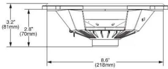
| Mounting Diameter | 8.7 x 5.8(218 x 147) |
| Mounting Depth | 2.8(71) |
| Grille/Trim Ring | NO |
See page 4 for additional dimensions


CEA 2031
Power handling on Rockford Fosgate speakers conform to CEA-2031 industry standards. This means your speaker has the capacity to handle power under continuous demand, not instantaneous power handling that over time can damage voice coils.
VERIFIED WITH KLIPPEL
To adorn the 'Verified with Klippel' mark, the qualifying company's loudspeaker engineering personnel must be trained and certified by Klippel prior to using the three separate Klippel systems to design, develop and test. Rockford Fosgate has made the investment in Klippel to deliver the best possible speakers and subwoofers to their customers.
TMS69


Contents
• (2) TMS69 Speakers
• (2) Speaker Grilles
• (2) Mounting Rings
• (2) Cutting Templates
• (16) Mounting Screws
• (1) Main Harness
• (2) Saddlebag Harnesses
- Plastic Wire Tie Wraps
- Plastic Cable Tie Mounts
Installation Tools
The following is a list of suggested tools needed for installation:
- Drill
• Jigsaw / Airsaw
- 1/8" Drill Bit
- 5/16" Drill Bit
- 3/4" Hole Saw
- Wire Cutters
- Small Flat Blade Screwdriver
• Phillips Screwdriver - Torx Drivers
- Socket set
- Masking Tape
Installation Considerations
This section focuses on some considerations for installing your Harley-Davidson® saddlebag lid speaker kit.
If you feel unsure about installing this system yourself, have it installed by a qualified technician.
When drilling holes, make sure what is on the other side. Be sure that any electrical, fuel lines or any other important components are free and clear from the area.

WARNING
Before installation, disconnect the battery negative (-) terminal to prevent damage to the unit, fire and/or possible injury.
Before beginning any installation, follow these simple rules:

CAUTION
Be sure to carefully read and understand the instructions before attempting to install these speaker kits.

CAUTION
- Consult your motorcycle's service manual for model specific information. Models may differ from year to year depending on factory options and aftermarket accessories added.
- This speaker kit is specifically designed to work with Rockford Fosgate's Punch® and Power series compact amplifiers.
- With the addition of an amplifier or source unit, be sure that your current charging system is in proper working order.
- Visit rockfordfosgate.com for more comprehensive product information.
- Visit our YouTube channel for comprehensive installation videos demonstrating complete installation guides and install tips.
NEED HELP WITH YOUR INSTALLATION?

YOUTUBE VISIT OUR CHANNEL FOR A COMPLETE INSTALLATION VIDEO AND OTHER TIPS WWW.YOUTUBE.COM/USER/ROCKFORDFOSGATE
Applicable Models:
1998 to 2013 Harley-Davidson® Motorcycles with Factory Saddlebags
This saddlebag lid speaker kit is designed to work with Rockford Fosgate's compact chassis Punch® and Power series amplifiers.
Step 1. Remove the saddlebag lids, seat, gas tank and fairing cover from the motorcycle.
Step 2. Using masking tape, tape over the painted portion of your saddlebag lids.
NOTE: This will prevent any scratching of the factory paint during the installation process.
NOTE: Be sure the template sits snug on all sides and corners of the saddlebag lid before securing.
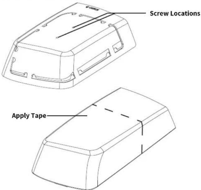
Step 3. Apply the template to the saddlebag lid and secure using (2) screws that came with the kit.
NOTE: There is a brake and clutch side specific template for each lid. You can use an 1/8" drill bit to predrill holes before screwing the template to the lid. Be sure the template is secured and wont move.
Step 4. Once the template is secured, use a 5/16" drill bit and drill holes in the template.
NOTE: We suggest drilling at every segment to make sawing easier.
Step 5. Using a jigsaw, follow along the template.
NOTE: DO NOT cut the segments of the template until all of the slots have been cut. This will help maintain accuracy and fitment for the grilles.
NOTE: When cutting, be sure that the saw blade stays in between the edges of the template. Cutting into the template will lead to fitment issues.
Step 6. Next you will attach the speaker, grille and mounting ring to the lid using the supplied screws.

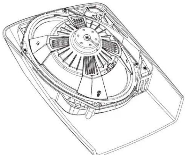
NOTE: It is easiest to place the grill into the hole that has been cut into the lid and place upside down on a bench. Then place the appropriate mounting ring onto the grille, along with the speaker. Secure with the supplied screws.
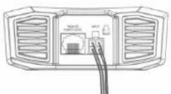
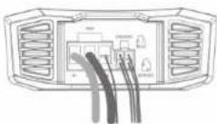
Step 7. Run the main harness up the back bone of the bike and to the amplifier under the fairing.
Step 8. Drill a 3/4" hole on the inside of the bag for the saddlebag harness. Once the hole is drilled, insert through the hole and secure the grommet.
Step 9. Place the adhesive backed plastic cable tie mounting tab to the inside of the bag.

Step 10. Route the wire along the inside of the bag and secure to the plastic cable tie mounting tab with the supplied plastic wire ties.
Step 11. Reattach your saddlebag lid and connect the harness to the speaker.
Step 12. Test system and reassemble the motorcycle.
Rockford Corporation offers a limited warranty on Rockford Fosgate products on the following terms:
Length of Warranty
POWER Amplifiers - 2 Years
BMW® Direct Fit Speakers – 2 Years
PUNCH® & PRIME® Amplifiers - 1 Year
Speakers, Signal Processors, Accessories and Capacitors – 1 Year
All marine, motorcycle, motorsport products - 2 Years
Any Factory Refurbished Product – 90 Days (receipt required)
What is Covered
This warranty applies only to Rockford Fosgate products sold to consumers by authorized Rockford Fosgate dealers in the United States of America.
Products purchased by consumers from an Authorized Rockford Fosgate Dealer in another country are covered only by that country's Distributor and not by Rockford Corporation.
Who is Covered
This warranty covers only the original purchaser of Rockford product purchased from an authorized Rockford Fosgate dealer in the United States. In order to receive service, the purchaser must provide Rockford with a copy of the receipt stating the customer name, dealer name, product purchased and date of purchase.
Products found to be defective during the warranty period will be repaired or replaced (with a product deemed to be equivalent) at Rockford's discretion.
What is Not Covered
- Damage caused by accident, abuse, improper installation, operations, theft, water (on non-Element Ready products).
- Any cost or expense related to the removal or reinstallation of product.
- Service performed by anyone other than Rockford or an authorized Rockford Fosgate service center.
- Any product which has had the serial number defaced, altered, or removed.
- Subsequent damage to other components.
- Any product purchased outside the U.S.
- Any product not purchased from an authorized Rockford Fosgate dealer. Refer to rockfordfosgate.com dealer locator for more detail.
Limit on Implied Warranties
Any implied warranties including warranties of fitness for use and merchantability are limited in duration to the period of the express warranty set forth above. Some states do not allow limitations on the length of an implied warranty, so this limitation may not apply. No person is authorized to assume for Rockford Fosgate any other liability in connection with the sale of the product.
How to Obtain Service
Please call 1-800-669-9899 for Rockford Customer Service. You must obtain an RA# (Return Authorization number) to return any product to Rockford Fosgate. You are responsible for shipment of product to Rockford.
EU Warranty
This product meets the current EU warranty requirements, see your Authorized dealer for details.
Installation assistance available at: RFTECH www.rockfordfosgate.com/rftech
- CAUTION
- STEP 1 - INPUT
- INPUT CLIP INDICATOR SETUP
- STEP 2 - INPUT
- STEP 3 - INPUT
- AMPLIFIER CLIP INDICATOR SETUP
- STEP 4 - INPUT
- STEP 5 - INPUT
- STEP 6 - INPUT
- STEP 7 - OUTPUT
- STEP 8 - OUTPUT
- OUTPUT CLIP INDICATOR SETUP
- STEP 9 - OUTPUT
- STEP 10 - OUTPUT
- ROCKFORD FOSGATE
- POWER
- INTRODUCTION
- SPECIFICATIONS
- DEAR CUSTOMER
- VISIT OUR WEB SITE FOR THE LATEST INFORMATION ON ALL ROCKFORD PRODUCTS: WWW.ROCKFORDFOSPALE.COM
- TABLE OF CONTENT
- PRACTICE SAFE SOUND
- SAFELY
- INSTALLATION INSTALLATION
- CONTENTS
- INSTALLATION CONSIDERATIONS
- MOUNTING LOCATIONS
- TRUNK MOUNTING
- PASSENGER COMPARTMENT MOUNTING
- ATVS, GOLF CARTS OR MOTORCYCLE
- BATTERY AND CHARGING
- WIRING THE SYSTEM
- WARNING
- WIRE HARNESS COLOR CODE
- ADJUSTING CROSSOVER FREQUENCY
- 2/4 CHANNEL SWITCH
- HIGH LEVEL INPUT
- PUNCH EQ
- REMOTE PUNCH LEVEL CONTROL (OPTION)
- QUICK INSTALL
- OPERATION
- TROUBLESHOOTING
- ROCKFORD CORPORATION OFFERS A LIMITED WARRANTY ON ROCKFORD FOSGATE PRODUCTS ON THE FOLLOWING TERMS: LENGTH OF WARRANTY
- WHAT IS COVERED
- WHO IS COVERED
- WHAT IS NOT COVERED
- LIMIT ON IMPLIED WARRANTIES
- HOW TO OBTAIN SERVICE
- EU WARRANTY
- RFTECH
- SETUP DISC
- AUDIO TRACKS
- CD-ROM CONTAINS
- CERTIFICATE OF PERFORMANCE VERIFICATION
- TOCKFORD ROSALE
- ROCKFORD FOSQALE
- ARE YOU ENGINEERED TO ROCK
- GET A ONE-YEAR EXTENDED WARRANTY WHEN YOU USE A MATCHING ROCKFORD FOSGATE AMPLIFIER INSTALLATION KIT WITH YOUR AMPLIFIER
- HOW TO OBTAIN SERVICE UNDER THE EXTENDED WARRANTY PROGRAM
- TABLE OF CONTENTS
- SAFETY
- INSTALLATION TOOLS
- NEED HELP WITH YOUR INSTALLATION
- YOUTUBE VISIT OUR CHANNEL FOR A COMPLETE INSTALLATION VIDEO AND OTHER TIPS WWW.YOUTUBE.COM/USER/ROCKFORDFOSGATE
- APPLICABLE MODELS
- 1998 TO 2013 HARLEY-DAVIDSON® MOTORCYCLES WITH FACTORY SADDLEBAGS
- ROCKFORD CORPORATION OFFERS A LIMITED WARRANTY ON ROCKFORD FOSGATE PRODUCTS ON THE FOLLOWING TERMS
- LENGTH OF WARRANTY
- INSTALLATION ASSISTANCE AVAILABLE AT: RFTECH WWW.ROCKFORDFOSGATE.COM/RFTECH
Brand : Rockford Fosgate
Model : HD9813RK
Category : Loudspeaker