
CHE-HDBTWP110K - Audio / Video Comprehensive - Free user manual and instructions
Find the device manual for free CHE-HDBTWP110K Comprehensive in PDF.

| Product Type | HDBaseT Wall Plate Transmitter/Receiver |
| Model | CHE-HDBTWP110K |
| Brand | Comprehensive |
| Video Resolution Support | Up to 4K@60Hz 4:4:4 |
| HDMI Version | HDMI 2.0 |
| HDCP Version | HDCP 2.2 |
| Transmission Distance | Up to 100m via Cat6/6a/7 cable |
| Audio Support | PCM, Dolby Digital, DTS, up to 7.1ch |
| Input/Output Interface | 1x HDMI input (or output), 1x RJ45, 1x IR extender, 1x RS232 |
| Power Supply | PoE (Power over Ethernet) or 48V DC via included adapter |
| Power Consumption | < 15W |
| Dimensions (W x H x D) | 120mm x 80mm x 25mm (wall plate form factor) |
| Weight | Approx. 0.3 kg |
| Housing Material | Metal and plastic |
| Operating Temperature | 0°C to 40°C |
| Humidity Range | 10% to 85% RH (non-condensing) |
| Main Functions | Extends HDMI signal over long distance, supports IR pass-through, RS232 control, EDID management |
| Maintenance | Wipe with dry cloth; avoid liquid cleaners |
| Safety | Overcurrent and short-circuit protection |
| Spare Parts & Repairability | Power adapter and cable; consult manufacturer for repairs |
| General Information | Compliant with HDBaseT 3.0 standard; supports PoE for simplified installation |
Frequently Asked Questions - CHE-HDBTWP110K Comprehensive
User questions about CHE-HDBTWP110K Comprehensive
0 question about this device. Answer the ones you know or ask your own.
Ask a new question about this device
Download the instructions for your Audio / Video in PDF format for free! Find your manual CHE-HDBTWP110K - Comprehensive and take your electronic device back in hand. On this page are published all the documents necessary for the use of your device. CHE-HDBTWP110K by Comprehensive.
USER MANUAL CHE-HDBTWP110K Comprehensive
natural_image
Exterior view of a white HDMI HDBT device with ports and connectors, mounted on a black base (no readable text or symbols beyond branding)Operation Manual
SAFETY PRECAUTIONS
Please read all instructions before attempting to unpack, install or operate this equipment and before connecting the power supply.
Please keep the following in mind as you unpack and install this equipment:
• Always follow basic safety precautions to reduce the risk of fire, electrical shock and injury to persons.
- To prevent fire or shock hazard, do not expose the unit to rain, moisture or install this product near water.
• Never spill liquid of any kind on or into this product.
- Never push an object of any kind into this product through any openings or empty slots in the unit, as you may damage parts inside the unit.
- Do not attach the power supply cabling to building surfaces.
- Use only the supplied power supply unit (PSU). Do not use the PSU if it is damaged.
- Do not allow anything to rest on the power cabling or allow any weight to be placed upon it or any person walk on it.
- To protect the unit from overheating, do not block any vents or openings in the unit housing that provide ventilation and allow for sufficient space for air to circulate around the unit.
- Please completely disconnect the power when the unit is not in use to avoid wasting electricity.
CONTENTS
-
Introduction...... 1
-
Applications .... 1
-
Package Contents ...... 2
-
System Requirements ...... 2
-
Features ...... 2
-
Operation Controls and Functions ...... 4
6.1 Front Panel....4
6.2 Rear Panel 5
6.3 WebGUI Control 6
6.3.1 Switch Tab 8
6.3.2 Automation Tab....10
6.3.3 EDID Settings Tab....12
6.3.4 System Settings Tab....14
6.4 RS-232 Control....15
6.5 Telnet Control.... 16
6.6 RS-232 and Telnet Commands ...... 17
-
Connection Diagram 31
-
Specifications.... 32
8.1 Technical Specifications .... 32
8.2 Video Specifications....33
8.3 Audio Specifications....34
8.4 Cable Specifications .... 34
8.5 HDBaseT Features 35
- Acronyms ...... 36
1. INTRODUCTION
The CHE-HDBTWP110K Wallplate Extender is an HDMI and VGA switch with audio embedding and HDBaseT output. The wallplate is designed for use with US single-gang sized enclosures. This Transmitter can send uncompressed high-definition video/audio over a single cable up to a distance of 100 meters at 1080p@60Hz. The HDMI input supports resolutions up to 4K@60Hz (4:4:4, 8-bit) and the VGA input supports resolutions up to WUXGA (RB). With the use of the 3.5mm audio input, stereo audio may be embedded with VGA or DVI sources as well.
Despite HDBaseT's 10.2Gbps bandwidth limitation, high bandwidth 4K UHD HDMI video sources, up to and including 4K@60Hz (4:4:4, 8-bit), can be supported and will be automatically converted to 8-bit color, or the 4:2:0 color space when necessary.
Signal management features such as automatic switching based on input signal and hot plug detection enable convenient hands-free operation. A multi-function button on the face of the unit provides access to an information OSD as well as allowing manual
input selection. When paired with a compatible Receiver, additional functionality such as EDID management, HDCP management and basic event automation (which can send customized RS-232 or CEC commands to external devices automatically) also becomes accessible.
This Transmitter (PD) may be powered locally or via 48V PoH from a compatible HDBaseT Receiver (PSE), which allows for greater flexibility in installations. The unit can be controlled via the front panel button with OSD. When paired with a compatible Receiver it may also be controlled via Web GUI, Telnet, and RS-232 making it exceptionally versatile.
2. APPLICATIONS
• Household entertainment sharing and control
- Lecture halls, auditoriums and classroom
• Houses of worship
• Conference rooms and boardrooms
- Hotel event spaces
3. PACKAGE CONTENTS
• 1×HDMI/VGA over HDBaseT Transmitter
- 1×2-pin Terminal Block
• 1×US 1-Gang Faceplate
• 1×HDMI over HDBaseT Receiver (PSE)
• 1×48V/0.83A DC Power Adaptor
- 1×Power Cord
• 1×Operation Manual
4. SYSTEM REQUIREMENTS
- HDMI or VGA source equipment such as a media player, video game console or set-top box.
- A compatible HDBaseT Receiver is required. An HDBaseT Receiver capable of suppling 48V PoH is recommended.
- The use of industry standard Cat.6, Cat.6a or Cat.7 cable is highly recommended.
- The use of "Premium High Speed HDMI" cable is highly recommended.
5. FEATURES
• HDMI 2.0 and DVI 1.0 compliant
• HDCP 2.2 and HDCP 1.x compliant
- 1 HDMI input
• 1 VGA input with 3.5mm mini-jack audio input
• Wall plate is designed for US one-gang sized enclosures
• Supports HDMI input resolutions up to 4K@60Hz (4:4:4, 8-bit)
• Supports VGA input resolutions up to WUXGA (RB)
- Analog stereo audio may be embedded with VGA or DVI/HDMI sources
- HDBaseT output supports resolutions up to 4K@60Hz (4:2:0, 8-bit) with automatic color space conversion of 4K@50/60Hz (4:4:4, 8-bit) or 4K@any (10/12-bit) sources
- Simultaneous transmission of uncompressed video, audio and
data over a single 100m/328ft Cat.5e/6/7 cable at 1080p60 and 70m/230ft at 4K
- HDBaseT feature support: HD Video and Audio, 100BaseT Ethernet, 48V PoH, and Control (bidirectional IR/RS-232 pass-through)
- Supports standard 48V PoH from Receiver (PSE) to Transmitter (PD) (compatible Transmitters only)
Notes:
- The 48V PoH function is designed to power compatible Transmitter units only. Non-PoH Transmitters will need their own power supply. Other brands of Transmitter may not be compatible.
- The use of “Premium High Speed HDMI” cables is highly recommended for displaying 3D and 4K content and compatible display equipment is required.
• Supports CEC bypass - User activated information OSD
- Unit may be powered locally or via 48V PoH from a compatible HDBaseT Receiver (PSE)
- Supports manual input selection or automatic input selection with hot plug detection
- Basic signal event automation (via RS-232 or CEC w/ compatible Receiver)
- USB port supports firmware update and powering of 5V/500mA devices
- Front panel LEDs indicate HDCP mode, input source, and power
- Controllable via a multi-function front panel button with OSD, or via WebGUI, Telnet, and RS-232 (w/ compatible Receiver only)
6. OPERATION CONTROLS AND FUNCTIONS
6.1 Front Panel
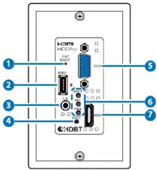
1 FAC RESET Button: Press and hold for 5 seconds to reset the unit to its factory defaults.
2 SERV.: This slot is reserved for firmware update use only. Note: This USB port can provide up to 500mA to connected devices.
3 L/R IN: Connect to the stereo analog output of a device such as an audio player or PC for embedding into the HDBaseT output.
4 INFO Button: A short press of this button will switch between the available inputs. Pressing and holding this button for 2 seconds will activate the information OSD.
5 VGA IN: Connect to VGA source equipment such as a PC or laptop.
6 HDCP LED: This LED indicates the HDCP mode of the current input. Green indicates Follow Display mode, orange indicates Follow Source mode, off indicates HDCP is disabled.
SRC LED: This LED indicates which source is currently selected. Green indicates the HDMI input, orange indicates the VGA input.
PWR LED: This LED will illuminate to indicate the unit's power and link status. Orange indicates the unit is on and receiving power, green indicates the unit is on, receiving power, and has successfully
linked to a compatible Receiver.
7 HDMI IN: Connect to HDMI source equipment such as a media player, game console or set-top box.
6.2 Rear Panel

1 CAT5e/6/7 OUT: Connect to a compatible HDBaseT Receiver with a single Cat.5e/6/7 cable for transmission of all data signals.
2 DC 12V: Connect a 12V DC power adapter to the twin terminal block and connect it to an AC wall outlet for power. (Optional, not required when powered by PoH from the Receiver.)
Receiver's Front and Rear Panels


1 STD/UPDATE: This switch is reserved for factory use only.
RS-232 OUT: Connect to a serial controllable device for the extension of RS-232 signals.
3 LAN: Connect to an Ethernet device or to your local network as appropriate.
4 POWER LED: This LED will illuminate to indicate the unit is on and receiving power.
5 LINK LED: This LED will illuminate solid when both Transmitter and Receiver are connected and communicating with each other properly.
6 DC 48V: Plug the 48V DC power adapter into this port and connect it to an AC wall outlet for power.
7 IR1: Not functionanl
8 IR2 : Not functionanl
9 CAT5e/6/7 IN: Connect to a compatible HDBaseT Transmitter with a single Cat.5e/6/7 cable for transmission of all data signals.
10 HDMI OUT: Connect to an HDMI TV, monitor or amplifier for digital video and audio output.
6.3 WebGUI Control
• Device Discovery APP
Please obtain the "Device Discovery" software from your authorized dealer and save it in a directory where you can easily find it.
Connect the unit and your PC/Laptop to the same active network and execute the “Device Discovery” software. Click on “Find Devices on Network” and a list of devices connected to the local network will show up indicating their current IP address.
Note: The unit's default IP address is 192.168.1.50.

By clicking on one of the listed devices you will be presented with the network details of that particular device.
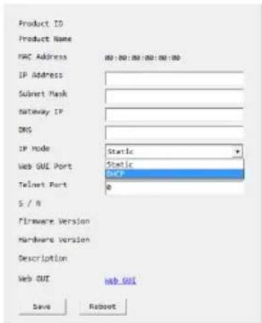
1) IP Mode: If you choose, you can alter the static IP network settings for the device, or switch the unit into DHCP mode to automatically obtain proper network settings from a local DHCP server. To switch to DHCP mode, please select DHCP from the IP mode drop-down, then click "Save" followed by "Reboot".
2) WebGUI Hotkey: Once you are satisfied with the network settings, you may use them to connect via Telnet or WebGUI. The network information window provides a convenient link to launch the WebGUI directly.
Note: WebGUI support requires the use of a compatible HDBaseT Receiver with an Ethernet port.
- WebGUI Overview
After connecting to the WebGUI's address in a web browser, the login screen will appear. Please enter the appropriate user name and password then click "Submit" to log in.
Note: The default user name and password is "admin".

On the left side of the browser you will see the following menu tabs where all primary functions of the unit (Switch, Automation, EDID Settings and System Settings) are controllable via the built in WebGUI. The individual functions will be introduced in the following sections.
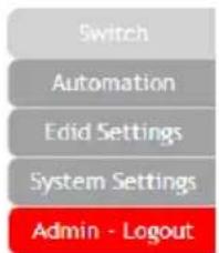
Clicking the red "Logout" tab will automatically log the currently connected user out of the WebGUI and return to login page.
6.3.1 Switch Tab
This tab provides video/audio routing control as well as control over HDCP behavior, freerun settings, and naming of the Inputs and Output. To assign a new video route, please click the Output button and then click on the button of the preferred Input port to route. As you select each button they will change their color to orange. The new route will become active immediately and the routing information displayed on the buttons will change accordingly.

1) Output: Click on the main button to begin routing selection. Click on the Camera icon (■) to mute or unmute the output. Click the Edit icon (E) to modify additional Output settings.

2) Edit Output: This window provides options to rename the Output, enable auto switching, set audio routing, and configure freerun.
■ Output Name: Provides a way to change the name of the Output port. Click on "Save" to confirm and activate any changes.
■ Auto Mode: Enable or disable the auto input switching mode.
■ Audio Route: Control the audio used when the HDMI input is active. Selecting “Bypass” will use the HDMI signal’s normal audio. Selecting “External” will use the analog stereo audio.
■ Freerun Mode: Enable or disable the video freerun function. When this is enabled, the selected freerun color will be displayed on the screen if there is no live source on the selected input.
■ Freerun Color: Select the color to display when freerun is active. Available choices are: Black, Red, Blue, and Colorbars.
3) Input: Rename either Input or modify the HDCP behavior (Input 2 only) by clicking on the Edit icon (☐) to open the editing window. Click on "Save" to confirm and activate any changes made to a name. Changes made to the HDCP behavior are applied immediately.
■ Apple Mode: Completely disables HDCP support on the input.
■ Follow In: HDCP support follows the HDCP mode required by the connected source device.
■ Follow Out: HDCP support follows the HDCP mode supported by the connected sink.
6.3.2 Automation Tab
The Automation tab provides control over the unit's automatic control command broadcast behavior when the specified system Automation Events occur. Automation commands may be sent to 3rd party devices via standard CEC, or customizable RS-232.
Note: Sending RS-232 commands requires the use of a compatible HDBaseT Receiver with an RS-232 port.
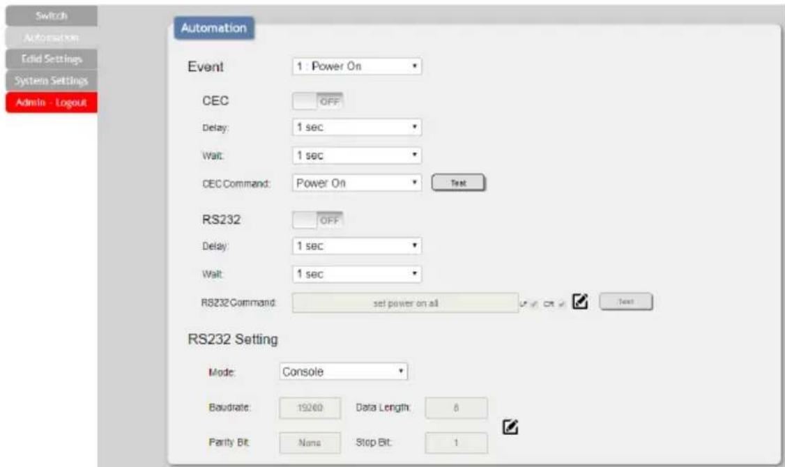
1) Event: Use the dropdown to select the Automation Event to configure. Available Automation Events are:
- Power On: This unit is powered on.
- Out A Source Active: The currently selected input changes from inactive to active.
- Out A Source Lost: The currently selected input changes from active to inactive.
■ CEC: Enable or disable sending a CEC command when the currently selected Automation Event is activated.
Note: CEC support must be enabled on the connected HDMI device.
■ Delay: Set the length of time, in seconds, that the specified Automation Event must continue to be true before sending the defined CEC command.
■ Wait: Set the length of time, in seconds, to wait after this CEC Automation Event has been activated before ANY other Automation Event can be detected.
■ CEC Command: Set the CEC command to send when the specified Automation Event is activated. Clicking the "Test" button will send the command immediately. Available CEC commands are:
- Power Off: Turn off the connected HDMI display device.
- Power On: Turn on the connected HDMI display device.
- Active Source: Force the connected HDMI display device to switch to the HDMI input that this unit is connected to.
Note: Not all HDMI devices support all CEC commands.
■ RS-232: Enable or disable sending an RS-232 command when the currently selected Automation Event is activated.
Note: The RS-232 port must be in "Control" mode to send commands to external devices.
■ Delay: Set the length of time, in seconds, that the specified Automation Event must continue to be true before sending the defined RS-232 command.
■ Wait: Set the length of time, in seconds, to wait after this RS-232 Automation Event has been activated before ANY other Automation Event can be detected.
■ RS-232 Command: Click the Edit icon (☑) to define the RS-232 command to send when the specified Automation Event is activated. Clicking the "Test" button will send the command immediately.
2) RS-232 Setting: Provides controls to configure the settings and behavior of the RS-232 port.
■ Mode: Switch the behavior of the RS-232 port between "Console" and "Control". When "Console" is selected, the unit can receive and be controlled directly via RS-232 commands. When "Control" is selected the RS-232 port can send Automation commands to control other devices.
■ RS-232 Setting Edit: Click on the Edit icon (☐) to configure the various RS-232 port settings including baud rate, data length, parity and stop bits.
6.3.3 EDID Settings Tab
This tab provides control over the EDID behavior of the unit. There are six internal EDIDs, two customer uploaded EDIDs, and one sink sourced EDID that can be assigned to each input port individually. The sink EDID and both Customer EDIDs are also available for download to the connected PC.

1) Customer EDID Settings: Manage the uploadable User EDID content.
■ Save Name: Type the preferred name for the User EDID in the space provided then click "Save Name" to confirm the change.
■ Download: Click to download and save the current User EDID as a file (*.bin) on the connected PC.
■ Upload: Click to upload a previously saved EDID file (*.bin) from the connected PC into the User EDID slot.
2) Sink EDID Download: Select and save the EDID from a connected display.
- Drop-down Menu: Select the sink to read an EDID from for download.
■ Download: Click to download the EDID from the selected sink as a file (*.bin) to the connected PC.
3) EDID Mode: This dropdown controls how EDIDs are assigned to the unit's Inputs.
■ All: Selecting this will allow the assignment of a single EDID to all Inputs simultaneously.
■ Appoint: Selecting this allows for a different EDID to be assigned to each Input.
4) Set EDID Input Content: This section provides a way to set the EDID to use with the selected Input.
■ IN 1/IN 2/All Input: Click the appropriate buttons to select the preferred Input(s) and open the EDID Source table for assigning an EDID.
■ EDID Source: Click the EDID to assign to the selected Input. Once the EDID has been selected, the change will be occur immediately.
The EDIDs available in the EDID Source table are:
| EDID Source | EDID Content |
| 8bit/2D/PCM/1080p/2CH | 1080p@60Hz, LPCM 2.0 |
| 8bit/2D/PCM/1080p/MCH | 1080p@60Hz, LPCM 7.1+Bitstream |
| 12bit/2D/PCM/4K2K@30/2CH | 4K@30Hz, LPCM 2.0 |
| 12bit/2D/PCM/4K2K@30/MCH | 4K@30Hz, LPCM 7.1+Bitstream |
| 12bit/2D/PCM/4K2K@60/2CH | 4K@60Hz, LPCM 2.0 |
| 12bit/2D/PCM/4K2K@60/MCH | 4K@60Hz, LPCM 7.1+Bitstream |
| USER 1 | The currently uploaded Customer EDID |
| USER 2 | The currently uploaded Customer EDID |
| SINK A | EDID from the device on Output A |
6.3.4 System Settings Tab
This tab provides access to control a number of system configuration controls including displaying the unit's serial number, modifying the web access privileges, changing the IP configuration, performing a factory reset, rebooting the system, and updating the firmware.
1) Serial Number: Displays the unit's serial number.
2) Web User Setting: This section provides a way to change the password for the Administrator account. Click on "Save" to confirm and activate any changes made to these settings.
Note: The default password is "admin".
3) Network: The IP Address, Netmask and Gateway can be set manually, or DHCP can be enabled for automatic IP Configuration if your local network supports it. Click on "Save" to confirm and activate any changes made to these settings.
Note: If the IP address is changed then the IP address required for WebGUI and Telnet access will also change accordingly.
4) System
■ Reboot: Click this button to reboot the unit.
■ Factory Default: Click this button to reset the unit to the factory default settings.
5) Firmware Upgrade: To update the unit's firmware, click the "Choose File" button to open the file selection window and then select
the firmware update file (*.bin format) located on your local PC. After selecting the file, click the "Upgrade" button to begin the firmware update process. Once the process completes the unit will automatically reboot.
6.4 RS-232 Control
| Unit | |
| Pin | Definition |
| 1 | NC |
| 2 | TxD |
| 3 | RxD |
| 4 | NC |
| 5 | GND |
| 6 | NC |
| 7 | NC |
| 8 | NC |
| 9 | NC |
| Controlling PC | |
| Pin | Definition |
| 1 | NC |
| 2 | RxD |
| 3 | TxD |
| 4 | NC |
| 5 | GND |
| 6 | NC |
| 7 | NC |
| 8 | NC |
| 9 | NC |
| Serial Port Settings | |
| Baud Rate | 19200 |
| Data Bits | 8 |
| Parity Bit | None |
| Stop Bits | 1 |
| Flow Control | None |
Note: RS-232 support requires the use of a compatible HDBaseT Receiver with an RS-232 port.
6.5 Telnet Control
Before attempting to use Telnet control, please ensure that both the unit and the PC are connected to the same active networks.
| To Access the Command Line Interface (CLI) | |
| Windows 7 | Click Start, type “cmd” in the search field, and press Enter. |
| Windows XP | Click Start > Run, type “cmd”, and press Enter. |
| Mac OS X | Click Go > Applications > Utilities > Terminal. |
Once in the Command Line Interface (CLI) type "telnet" followed by the IP address of the unit (and the port number if it is non-standard) and then hit "Enter". This will connect us to the unit we wish to control. Type "help" to list the available commands. See below for reference.
Microsoft Windows [Version 6.1.7601]
Copyright (c) 2009 Microsoft Corporation. All rights reserved.
C:\Users\Administrator\telnet 192.168.1.50 23
Note: The default IP address is 192.168.1.50. If the IP address is changed then the IP address required for Telnet access will also change accordingly. Telnet support requires the use of a compatible HDBaseT Receiver with an Ethernet port.
6.6 RS-232 and Telnet Commands
| COMMAND |
| Description and Parameters |
| HELP← |
| Show all available commands. |
| ?← |
| Show all available commands. |
| GET FW VER← |
| Show the unit's firmware version. |
| GET MODEL NAME← |
| Show the unit's model name. |
| GET MODEL TYPE← |
| Show the unit's product type. |
| SET FACTORY DEFAULT← |
| Reset the unit to its factory defaults. |
| SET FACTORY IPCONFIG DEFAULT← |
| Reset the unit's IP configuration to the factory defaults. |
| SET SYSTEM REBOOT← |
| Reboot the unit. |
| GET MAC 1 ADDR← |
| Show the unit's MAC address. |
| SET IP MODE N1← |
| Set the IP address assignment mode. |
| Available values for N1: |
| STATIC [Static IP mode] |
| DHCP [DHCP mode] |
| GET IP MODE← |
| Show the current IP mode.GET IPCONFIG← |
| Show the current IP address details. |
| SET IPADDR N1← |
| Set the static IP Address.N1 = X.X.X.X [X = 0 ~ 255] |
| GET IPADDR← |
| Show the current IP address. |
| SET NETMASK N1← |
| Set the netmask address.N1 = X.X.X.X [X = 0 ~ 255] |
| GET NETMASK← |
| Show the current netmask. |
| SET GATEWAY N1← |
| Set the gateway address.N1 = X.X.X.X [X = 0 ~ 255] |
| GET GATEWAY← |
| Show the current gateway. |
| SET IN N1 NAME N2← |
| Set the name of input N1.N1 = 1 ~ 2 [Input number]N2 = {Name} [16 characters max] |
| GET IN N1 NAME← |
| Show input N1's current name.N1 = 1 ~ 2 [Input number] |
| SET OUT A NAME N1← |
| Set the name of the output.N1 = {Name} [16 characters max] |
| GET OUT A NAME← |
| Show the output's current name. |
| SET OUT A ROUTE N1← |
| Switch the output routing source to input N1.N1 = 1 ~ 2 [Input number] |
| GET OUT A ROUTE← |
| Show the output's current routing source. |
| GET IN TYPE LIST← |
| Show each input's video type. |
| GET OUT TYPE LIST← |
| Show the video type of the output. |
| SET OUT A MASK N1← |
| Enable or disable the mask setting on output N1.Available values for N1:OFF [Mask disabled]ON [Mask enabled]Note: When an output is masked, all video, including the banner, will be blanked out. |
| GET OUT A MASK← |
| Display the current output mask setting. |
| SET OUT AUTO MODE N1← |
| Enable or disable automatic source switching.Available values for N1:0 [Auto switch disabled]1 [Auto switch enabled] |
| GET OUT AUTO MODE← |
| Show the current auto switch mode state. |
| GET IN PORT NUMBER← |
| Show the number of inputs on the unit. |
| GET OUT PORT NUMBER← |
| Show the number of outputs on the unit. |
| GET IN N1 SYNC STATUS← |
| Show the current sync status of input N1.N1 = 1 ~ 2 [Input number]Available Responses:0 [No sync]1 [Sync is present] |
| GET OUT A SYNC STATUS← |
| Show the current sync status of the output.Available Responses:0 [No sync]1 [Sync is active] |
| SET ALL IN EDID MODE N1← |
| Enable or disable using the same EDID for all inputs.Available values for N1:ON [All mode]OFF [Appoint mode] |
| GET ALL IN EDID MODE← |
| Show the current state of the EDID assignment mode. |
COMMAND
Description and Parameters
SET ALL IN EDID N1←
Set the EDID to use when set to "All mode".
Available values for N1:
1 [8-bit/1080p/2CH LPCM]
2 [8-bit/1080p/MCH]
3 [12-bit/4K@30/2CH LPCM]
4 [12-bit/4K@30/MCH]
5 [12-bit/4K@60/2CH LPCM]
6 [12-bit/4K@60/MCH]
7 [User 1]
8 [User 2]
9 [Sink A]
GET ALL IN EDID←
Show the current "All mode" EDID.
SET IN N1 EDID N2←
Assign EDID N2 to input N1 in "Appoint mode".
N1 = 1 \~ 2 [Input number]
Available values for N1:
1 [8-bit/1080p/2CH LPCM]
2 [8-bit/1080p/MCH]
3 [12-bit/4K@30/2CH LPCM]
4 [12-bit/4K@30/MCH]
5 [12-bit/4K@60/2CH LPCM]
6 [12-bit/4K@60/MCH]
7 [User 1]
8 [User 2]
9 [Sink A]
GET IN N1 EDID←
Show the EDID currently assigned to input N1.
N1 = 1 \~ 2 [Input number]
| COMMAND |
| Description and Parameters |
| GET IN EDID LIST← |
| List all available EDID sources. |
| SET EDID N1 NAME N2← |
| Set the name of User EDID N1 to N2.N1 = 7 ~ 8 [EDID number]N2 = {Name} [16 characters max]Note: Only User EDIDs can be renamed. |
| GET EDID N1 NAME← |
| Show the current name of user EDID N1.N1 = 7 ~ 8 [EDID number] |
| SET IN 2 HDCP MODE N1← |
| Set the HDCP mode to use with the HDMI input.Available values for N1:0 [HDCP disabled]1 [Follow source]2 [Follow display] |
| GET IN 2 HDCP MODE← |
| Show the current HDCP mode. |
| SET AUDIO OUT A ROUTE N1← |
| Set the audio source to use with the HDMI input.Available values for N1:1 [HDMI audio]2 [Analog audio] |
| GET AUDIO OUT A ROUTE← |
| Show the current HDMI audio source.SET FREERUN A MODE N1← |
| Enable or disable the freerun feature when there is no detected input. |
| Available values for N1: |
| ON [Freerun enabled] |
| OFF [Freerun disabled] |
| GET FREERUN A MODE← |
| Show the current state of the freerun function. |
| SET FREERUN A TYPE N1← |
| Set the color to display when freerun is enabled and active. |
| Available values for N1: |
| 1 [Black] |
| 3 [Red] |
| 5 [Blue] |
| 10 [Color bar] |
| SET FREERUN A TYPE← |
| Show the current freerun display color. |
| GET FREERUN LIST← |
| List all available freerun colors. |
| GET AUTOMATION EVENT LIST← |
| List all Automation Event types. |
COMMAND
Description and Parameters
SET AUTOMATION EVENT N1 UART N2←
Enable or disable the specified Automation Event's RS-232 response.
Available values for N1:
1 [Power on]
2 [Out A source active]
3 [Out A source lost]
Available values for N2:
ON [Event enabled]
OFF [Event disabled]
GET AUTOMATION EVENT N1 UART←
Show the current state of the specified Automation Event's RS-232 response.
Available values for N1:
1 [Power on]
2 [Out A source active]
3 [Out A source lost]
SET AUTOMATION EVENT N1 UART DELAY N2 SEC←
Set the delay time that the specified Automation Event must continue to be true before sending the defined RS-232 command.
Available values for N1:
1 [Power on]
2 [Out A source active]
3 [Out A source lost]
N2 = 1 \~ 300 [Delay in seconds]
COMMAND
Description and Parameters
GET AUTOMATION EVENT N1 UART DELAY←
Show the delay time for the specified Automation Event's RS-232 response.
Available values for N1:
1 [Power on]
2 [Out A source active]
3 [Out A source lost]
SET AUTOMATION EVENT N1 UART WAIT N2 SEC←
Set the length of time to wait after an Automation Event's RS-232 response has been activated before ANY other Automation Event can be detected.
Available values for N1:
1 [Power on]
2 [Out A source active]
3 [Out A source lost]
N2 = 1 \~ 300 [Wait time in seconds]
Note: If both an RS-232 and CEC event is activated by the same Automation Event, the longer of the 2 wait times will be used.
GET AUTOMATION EVENT N1 UART WAIT←
Show the wait time for the specified Automation Event's RS-232 response.
Available values for N1:
1 [Power on]
2 [Out A source active]
3 [Out A source lost]
COMMAND
Description and Parameters
SET AUTOMATION EVENT N1 UART COMMAND N2←
Set the RS-232 command string to send when the specified Automation Event is activated.
Available values for N1:
1 [Power on]
2 [Out A source active]
3 [Out A source lost]
N2 = {Command} [Max 32 characters]
GET AUTOMATION EVENT N1 UART COMMAND←
Show the RS-232 command string to be sent when the specified Automation Event is activated.
Available values for N1:
1 [Power on]
2 [Out A source active]
3 [Out A source lost]
SET AUTOMATION EVENT N1 CEC N2←
Enable or disable the specified Automation Event's CEC response.
Available values for N1:
1 [Power on]
2 [Out A source active]
3 [Out A source lost]
Available values for N2:
ON [Event enabled]
OFF [Event disabled]
| COMMAND |
| Description and Parameters |
| GET AUTOMATION EVENT N1 CEC← |
| Show the current state of the specified Automation Event's CEC response. Available values for N1: 1 [Power on] 2 [Out A source active] 3 [Out A source lost] |
| SET AUTOMATION EVENT N1 CEC DELAY N2 SEC← |
| Set the delay time that the specified Automation Event must continue to be true before sending the defined CEC command. Available values for N1: 1 [Power on] 2 [Out A source active] 3 [Out A source lost] N2 = 1 ~ 300 [Delay in seconds] |
| GET AUTOMATION EVENT N1 CEC DELAY← |
| Show the delay time for the specified Automation Event's CEC response. Available values for N1: 1 [Power on] 2 [Out A source active] 3 [Out A source lost] |
COMMAND
Description and Parameters
SET AUTOMATION EVENT N1 CEC WAIT N2 SEC←
Set the length of time to wait after an Automation Event's CEC response has been activated before ANY other Automation Event can be detected.
Available values for N1:
1 [Power on]
2 [Out A source active]
3 [Out A source lost]
N2 = 1 \~ 300 [Wait time in seconds]
Note: If both an RS-232 and CEC event is activated by the same Automation Event, the longer of the 2 wait times will be used.
GET AUTOMATION EVENT N1 CEC WAIT←
Show the wait time for the specified Automation Event's CEC response.
Available values for N1:
1 [Power on]
2 [Out A source active]
3 [Out A source lost]
SET AUTOMATION EVENT N1 CEC COMMAND N2←
Set the CEC command to send when the specified Automation Event is activated.
Available values for N1:
1 [Power on]
2 [Out A source active]
3 [Out A source lost]
Available values for N2:
1 [CEC power off]
2 [CEC power on]
3 [CEC active source]
| COMMAND |
| Description and Parameters |
| GET AUTOMATION EVENT N1 CEC COMMAND← |
| Show the CEC command to be sent when the specified Automation Event is activated. Available values for N1: 1 [Power on] 2 [Out A source active] 3 [Out A source lost] |
| SET UART 1 MODE N1← |
| Set the RS-232 operation mode of the unit. Available values for N1: 1 [Console Commands] 2 [Control] |
| GET UART 1 MODE← |
| Show the current RS-232 operation mode. |
| SET UART 1 BAUDRATE N1← |
| Set the RS-232 baud rate. Available values for N1: 4800 [Baud rate] 7200 [Baud rate] 9600 [Baud rate] 14400 [Baud rate] 19200 [Baud rate] 38400 [Baud rate] 57600 [Baud rate] 115200 [Baud rate] |
| GET UART 1 BAUDRATE← |
| Show the current RS-232 baud rate.SET UART 1 STOP BIT N1← |
| Set the number of RS-232 stop bits to use. |
| N1 = 1 ~ 2 |
| GET UART 1 STOP BIT← |
| Show the current RS-232 stop bits setting. |
| SET UART 1 DATA BIT N1← |
| Set the number of RS-232 data bits to use. |
| N1 = 5 ~ 8 |
| GET UART 1 DATA BIT← |
| Show the current RS-232 data bits setting. |
| SET UART 1 PARITY N1← |
| Set the parity value for RS-232. |
| Available values for N1: |
| 0 [None] |
| 1 [Odd] |
| 2 [Even] |
| GET UART 1 PARITY← |
| Show the current RS-232 parity setting. |
Note: Commands will not be executed unless followed by a carriage return. Commands are not case-sensitive.
7. CONNECTION DIAGRAM
flowchart
graph TD
    PC["PC"] -->|Stereo Input| Media_Player["Media Player"]
    Media Player -->|HDMI Input| Media Player
    Media Player -->|VGA Input| Media Player
    Media Player -->|Cat.5e/6/7 Cable| CPU["Cable"]
    CPU -->|Cat.5e/6/7 Cable| RadioSystem["RX"]
    RadioSystem -->|HDMI Output| PowerSupply["Power Supply"]
    RadioSystem -->|RS-232 Equipped PC/Laptop| CPU
    CPU -->|UHDTV| UHDTV
    style CPU fill:#f9f,stroke:#333
    style Media Player fill:#ccf,stroke:#333
    style RadioSystem fill:#cfc,stroke:#333
    style Power Supply fill:#fcc,stroke:#333
8. SPECIFICATIONS
8.1 Technical Specifications (Transmitter)
| HDMI Bandwidth | 600MHz/18Gbps |
| HDBaseT Bandwidth | 340MHz/10.2Gbps |
| Input Ports | 1×HDMI1×VGA (HD-15)1×Stereo (3.5mm) |
| Output Port | 1×HDBaseT (RJ45) |
| Baud Rate | Up to 115200bps |
| Power Supply | 48V PoH or 12V/3A DC(US/EU standards, CE/FCC/UL certified) |
| ESD Protection | Human Body Model:±12kV (Air Discharge)±8kV (Contact Discharge) |
| Dimensions | 46mm×104mm×67mm (W×H×D)[Case Only]46mm×104mm×71.5mm (W×H×D)[All Inclusive] |
| Weight | 200g |
| Chassis Material | Aluminum |
| Silkscreen Color | White |
| Operating Temperature | 0°C–40°C/32°F–104°F |
| Storage Temperature | -20°C–60°C/-4°F–140°F |
| Relative Humidity | 20–90% RH (Non-condensing) |
| Power Consumption | 20.4W |
8.2 Technical Specifications (Receiver)
Input Port 1×Cat.5e/6/7
Output Port 1×HDMI
Pass-through Ports 1×RS-232 [9-pin D-sub]
1×LAN [RJ45]
Supported Resolutions 480i@60Hz - 4K@60Hz (4:2:0, 8-bit)
VGA@60Hz - WUXGA@60Hz (RB)
HDMI Cable Length 10m (1080p@60Hz, 12-bit)
5m (4K@60Hz, 4:4:4, 8-bit)
CAT5e/6 Cable Length 100m (1080p@60Hz, 12-bit)
70m (4K@60Hz, 4:2:0, 8-bit)
IR Frequency 30 - 50kHz (30 - 60kHz under ideal
conditions)
Baud Rate Up to 115200bps
Power Supply 48V/0.83A DC (US/EU standards, CE/FCC/
UL certified)
ESD Protection Human Body Model:
±8kV (Air Discharge)
±4kV (Contact Discharge)
Dimensions 128mm×25mm×108mm (W×H×D)
[Case Only]
8.4 Audio Specifications
| Analog Input | |
| Max Audio Level | 2Vrms |
| Impedance | 10kΩ |
| Type | Unbalanced |
8.5 Cable Specifications
| HDMI Cable Length | 1080p | 4K | |
| 8-bit | 12-bit | 8-bit | |
| Input | 15m | 10m | 5m |
| Output | 15m | 10m | 5m |
| Cat. Cable Length | 1080p | 4K |
| Cat.5e | 100m | 70m |
| Cat.6 | 100m | 70m |
| Cat.7 | 100m | 100m |
• Full HD Video (1080p)
- Up to 1080p@60Hz, 12-bit color
- Data rates lower than 5.3Gbps or below 225MHz TMDS clock
- Ultra HD Video (4K)
- 4K@24/25/30Hz & 4K@50/60Hz (YUV 4:2:0), 8-bit color
- Data rates higher than 5.3Gbps or above 225MHz TMDS clock
8.5 HDBaseT Features
| HDBaseT Feature | Supported |
| Video & Audio | √ |
| IR Pass-through | × |
| RS-232 Pass-through | × |
| Accept power from Receiver | √ |
| Send power to Receiver | × |
| LAN Pass-through | × |
9. ACRONYMS
| ACRONYM | COMPLETE TERM |
| Cat.5e | Category 5 (enhanced) cable |
| Cat.6 | Category 6 cable |
| Cat.7 | Category 7 cable |
| CEC | Consumer Electronics Control |
| DVI | Digital Visual Interface |
| HD | High-Definition |
| HDCP | High-bandwidth Digital Content Protection |
| HDMI | High-Definition Multimedia Interface |
| HDR | High Dynamic Range |
| HDTV | High-Definition Television |
| LED | Light-Emitting Diode |
| LPCM | Linear Pulse-Code Modulation |
| PC | Personal Computer |
| PD | Powered Device |
| PoH | Power over HDBaseT |
| PSE | Power Sourcing Equipment |
| UHD | Ultra-High-Definition |
| UHDTV | Ultra-High-Definition Television |
| USB | Universal Serial Bus |
| VGA | Video Graphics Array |
| WUXGA (RB) | Widescreen Ultra Extended Graphics Array (Reduced Blanking) |

Comprehensive® Connectivity Company
80 Little Falls Rd, Fairfield, NJ 07004
Phone: 1-800-526-0242
www.comprehensiveco.com
sales@comprehensiveco.com
- SAFETY PRECAUTIONS
- CONTENTS
- INTRODUCTION
- APPLICATIONS
- PACKAGE CONTENTS
- SYSTEM REQUIREMENTS
- FEATURES
- Notes:
- OPERATION CONTROLS AND FUNCTIONS
- Front Panel
- Rear Panel
- Receiver's Front and Rear Panels
- WebGUI Control
- • Device Discovery APP
- - WebGUI Overview
- Switch Tab
- Automation Tab
- EDID Settings Tab
- System Settings Tab
- 4) System
- RS-232 Control
- Telnet Control
- RS-232 and Telnet Commands
- COMMAND
- Description and Parameters
- SET ALL IN EDID N1←
- GET ALL IN EDID←
- SET IN N1 EDID N2←
- GET IN N1 EDID←
- SET AUTOMATION EVENT N1 UART N2←
- GET AUTOMATION EVENT N1 UART←
- SET AUTOMATION EVENT N1 UART DELAY N2 SEC←
- GET AUTOMATION EVENT N1 UART DELAY←
- SET AUTOMATION EVENT N1 UART WAIT N2 SEC←
- GET AUTOMATION EVENT N1 UART WAIT←
- SET AUTOMATION EVENT N1 UART COMMAND N2←
- GET AUTOMATION EVENT N1 UART COMMAND←
- SET AUTOMATION EVENT N1 CEC N2←
- SET AUTOMATION EVENT N1 CEC WAIT N2 SEC←
- GET AUTOMATION EVENT N1 CEC WAIT←
- SET AUTOMATION EVENT N1 CEC COMMAND N2←
- CONNECTION DIAGRAM
- SPECIFICATIONS
- Technical Specifications (Transmitter)
- Technical Specifications (Receiver)
- Audio Specifications
- Cable Specifications
- • Full HD Video (1080p)
- - Ultra HD Video (4K)
- HDBaseT Features
- ACRONYMS
Brand : Comprehensive
Model : CHE-HDBTWP110K
Category : Audio / Video