
KM-IP4100 - Video Production Software JVC - Free user manual and instructions
Find the device manual for free KM-IP4100 JVC in PDF.

| Product Type | Video Production Software (Live Production and Streaming Studio) |
| Brand | JVC (developed by Streamstar a.s.) |
| Model | KM-IP4100 |
| Intended Use | Multi-camera live production and live streaming |
| Supported Number of Cameras | 4 camera inputs (KM-IP4100) |
| Key Features | Live switching, PTZ camera control, replay capture with SRP/DRCS modes, character generator (CG) for text/crawl/timer/score, overlays, playlists, audio mixer with AFV, PIP and split screen layouts, streaming to multiple destinations, ISO recording, GPIO support |
| User Interface | Touch screen graphical user interface (GUI) divided into three sections: Production Layout, PGM/Camera Switching, Content Management & Settings |
| Operating System | Microsoft Windows (software application) |
| Replay System | 3 capture lengths (short/medium/long), slow-motion playback, freeze frame, wipes (lead-in/out animations), autocut to camera after replay |
| Character Generator (CG) | Text, crawl, timer/score objects with editable layers (background, text, dynamic data), support for PNG, FLV, MOV with alpha channel |
| Streaming | Multiple destinations, encoding profiles, save stream to file, start/stop all streams |
| Recording | PGM recording and ISO recording per camera (if selected as replay camera) |
| PTZ Camera Control | IP control of JVC PTZ cameras: pan/tilt/zoom/focus, presets (14 per camera), group presets (up to 14 groups with camera+preset pairs) |
| Audio Mixer | Multi-channel faders with level/peak indicators, Audio Follow Video (AFV), solo/mute, stereo lock, AUX input, IFB talk-back |
| GPIO Support | X-keys USB GPIO unit for tally and external device control (up to 10 configurable pins) |
| Support for Alpha Channel | Overlays and CG backgrounds: PNG, FLV, MOV (ProRes 4444) with transparency |
| Autocut Function | Automatic camera switching after media/playlist/replay ends; countdown timer on camera switches |
| Manual Format | PDF with 57 pages, available in English |
Frequently Asked Questions - KM-IP4100 JVC
User questions about KM-IP4100 JVC
0 question about this device. Answer the ones you know or ask your own.
Ask a new question about this device
Download the instructions for your Video Production Software in PDF format for free! Find your manual KM-IP4100 - JVC and take your electronic device back in hand. On this page are published all the documents necessary for the use of your device. KM-IP4100 by JVC.
USER MANUAL KM-IP4100 JVC
https://www.jvc.net/
All information in this document is subject to change without notice.
Copyright © Streamstar a.s., 2020. All rights reserved.
CONNECTED CAM STUDIO
MULTI-CAMERA LIVE PRODUCTION AND STREAMING STUDIOS
KM-IP6000 KM-IP4100
SMARTER - FASTER - EASIER
Table of Contents
Introduction 5
GUI overview 6
Software Start 6
Production Layout Section 8
Layers 8
Activity Indicators 8
Screen Layout - PIP 9
Screen Layout - Split Screen 10
Mixing Modes 10
Crossfade 11
Transitions. 11
PTZ Camera Control 12
GPIO 12
Camera Switching Section 13
PGM Monitor 13
Live Camera Monitors 14
Content Management and Settings Section 15
Media Tab 16
Media IN/OUT Points Editor 17
Autocut 19
Replays Tab 20
Replay Capture 21
Replay Modes 23
Replay Favorites and highlights 24
Autocut in Replays 25
Replay Wipes 25
Playlists Tab 26
Overlays Tab 27
CG Tab 28
CG List Pane Content 28
CG Operation Procedure....29
CG Object Construction and Editing 30
Text Layer Parameters Setup. 31
Crawl Text Layer Parameters Setup 31
CG Sequence 33
Timer/Score CG Objects 34
Timing Options Tab 35
Clock Parameters Setup. 35
Game Part Parameters Setup 36
Score Parameters Setup 36
Time/Score Controller 37
Automatic Data Control 38
Editing and XML preset 39
Settings Area Menu 40
SA - System Settings Tab 41
General / General tab 41
Camera Inputs tab 41
Synchronization tab 42
Ingest tab. 43
Output settings tab 43
Tally port selection tab 43
GPIO tab 44
Streaming - Streaming Destinations / Add New Destination / Encoding tabs 45
Recording - Recording / ISO recording tabs 46
Layers - Ingest / Logo tabs 46
Replays settings - Replay cameras / Replay settings / Lead In/Out Wipes tabs 47
Appearance - PIP / SPLIT / Background tabs 48
Audio settings 48
About 49
Exit 49
SA - Audio Tab 50
Audio Mixer 50
SA-Replays Tab 51
SA - JVC Camera Control Tab 52
IP Connect 52
Stream Settings 52
Control 53
Zoom and Focus 53
PTZ Presets 53
PTZ Groups Presets 54
PTZ Presets GUI 55
PTZ Groups Presets GUI 56
Support 57

natural_image
Crowd at a concert with performers on stage under dramatic lighting (no visible text or symbols)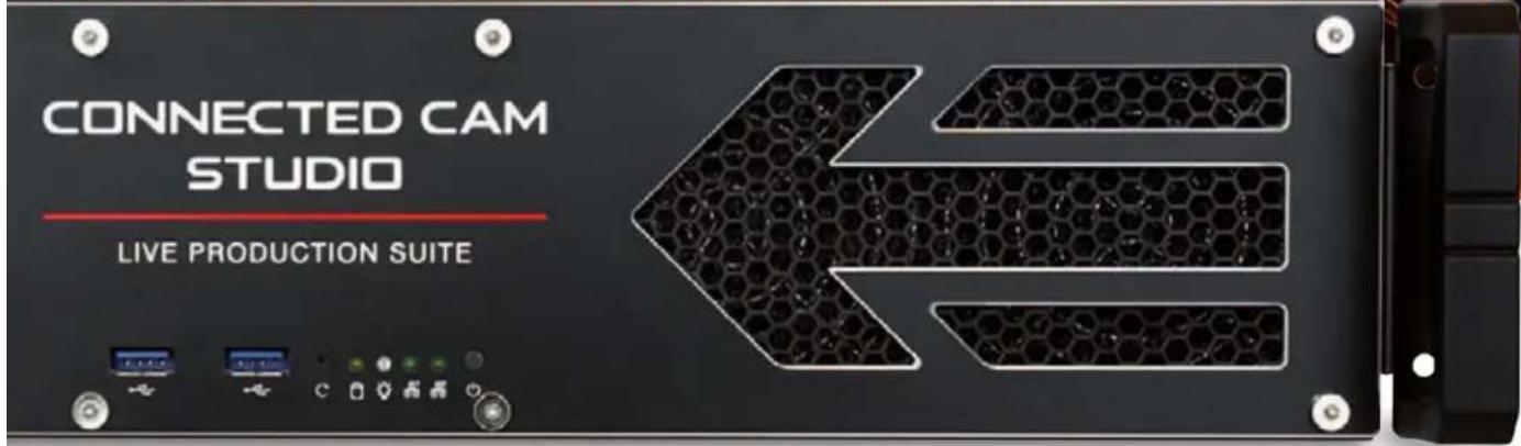
Copyright notice.
This document, all images, text, custom graphics, button icons, the collection and compilation and assembly thereof, and the overall look and design of this document are the exclusive property of Streamstar and are protected by international copyright laws. The JVC logo is property of, and used with permission of JVCKENWOOD corporation. The contents of this document may be used exclusively for information purposes as a learning resource for users of the described systems. Any other use including reproduction, modification, distribution, transmission, re-publication, display or performance of the contents of this document without prior written consent of Streamstar is expressly forbidden.
WELCOME
Congratulations on your purchase of the CONNECTED CAM STUDIO (CCS), the ideal live production system for the new generation of digital native media professionals.
CONNECTED CAM STUDIO - Live Production Software
The CONNECTED CAM STUDIO SW is specifically designed for live streaming production. It features a highly effective, intuitive touch screen user interface, that has been fine tuned and tested in thousands of real life productions. It offers professional live production features that will enable you to produce broadcast quality productions with unprecedented speed, efficiency, flexibility and extreme ease-of-use.
END USER LICENSE AGREEMENT
After the installation/reinstallation/update of the SW at first run the END USER LICENSE AGREEMENT page will be displayed. Read the text and confirm your agreement with its terms by pushing the active AGREE button at bottom right.
GUI - Graphical User Interface Overview
The Live Production Software is operated via an innovative, touch screen user interface, perfectly tuned for live streaming production.
It was designed to fulfill all the requirements of a live streaming production in the easiest, most efficient and user-friendly way. It allows a high level of sophistication, creative freedom, operational flexibility while maintaining a perfect control of every aspect of the production at all times.
The GUI is designed to allow the control of processes, functionalities and work flows in the most logical and practical way. Its layout is divided into 3 main, horizontal sections, containing logically related, operational elements and functions.
- PRODUCTION LAYOUT section - on top
- PGM & CAMERA SWITCHING section - in the middle
- CONTENT MANAGEMENT & SETTINGS section - at bottom
At the very bottom is an additional information bar displaying some helpful info on system status.

KM-IP6000
KM-IP4100
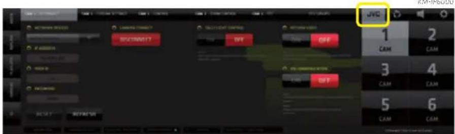
NOTE:
The GUI of the 4 cam version is modified to make the best use of the available desktop space. The LAYERS switches are located on the left of the PGM. (See 4 cam GUI screenshot on the left)
The PGM and Live Camera monitors desktop areas are occasionally used to display certain control elements, logically related to various functionalities. As you learn the GUI you will gradually find out how it all makes perfect sense and allows for incredible speed of operation.
SOFTWARE START
Start the CONNECTED CAM STUDIO SW application in a Windows OS usual way by double clicking its desktop icon.
natural_image
Red circular graphic with white arrows pointing inward, no text or symbols presentCREATING A PROJECT
CONNECTED CAM STUDIO
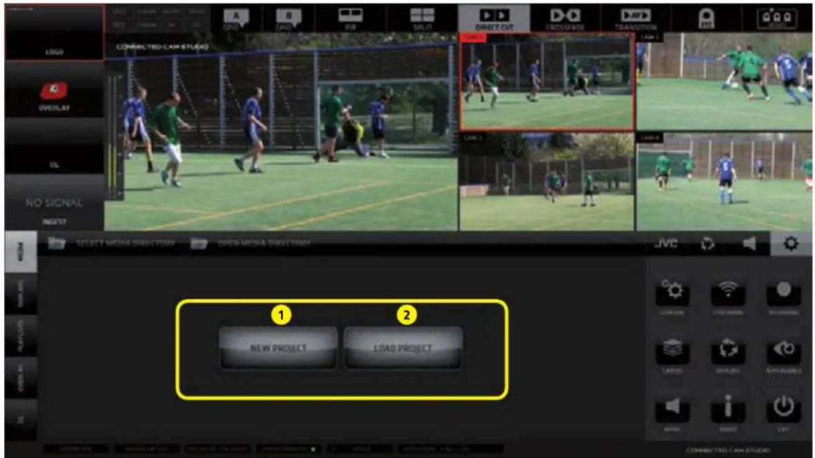
After application start the 1st GUI screen appears.
Two large buttons appear in the center of the CONTENT MANAGEMENT AREA.
1 - NEW PROJECT - a new project is created and you can start working immediately
2 - LOAD PROJECT - a dialog screen appears with a list of previously saved projects.
KM-IP4100
NOTE: To get you started a FIRST STEPS MANUAL is provided to get basic operational instructions.
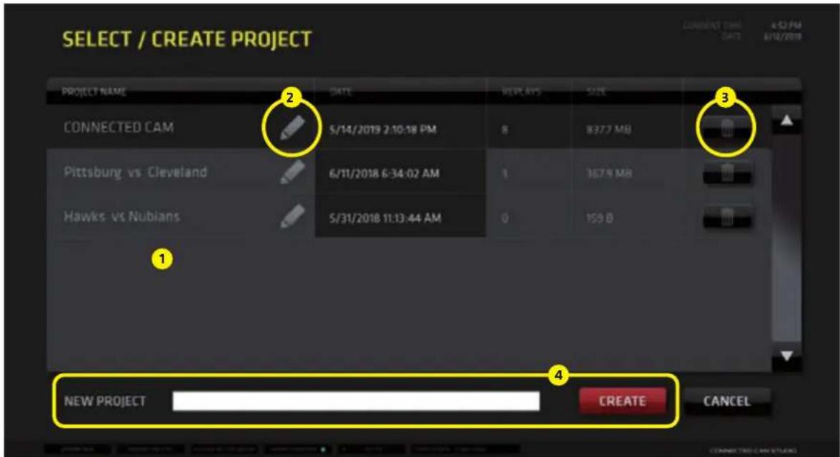
LOAD PROJECT dialog screen:
- Select an existing project by tap/click on its name in the list
- Edit the name of projects by tap/click on the PENCIL icon besides the names of projects
- Delete projects by tap/click on the TRASH Icon
- Create a new project by typing its name into the text input field and tap/click CREATE
PRODUCTION LAYOUT Section
KM-IP6000

It is located at the very top of the GUI and contains all important functionality controls for the creation of the layout and the overall appearance of your production (PGM output) as well as controls of certain related software functions. The 6 cam version (image above) and 4 camera version (image below) are differently organized to make the best use of screen space, but the functionality is identical.
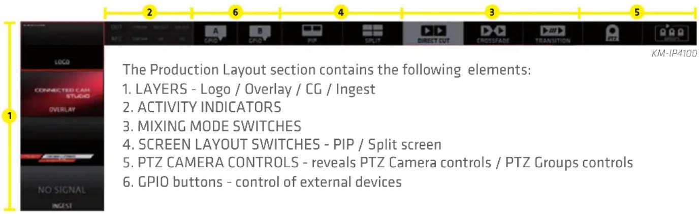
LAYERS:
Contains four switches for video layers superimposed on top of the camera layer:
LOGO on/off switch for the LOGO layer
(for a description go to the SETTINGS / LAYERS / LOGO section on page 46.)
OVERLAYS on/off switch for the OVERLAYS layer
(for a detailed description go to the CMA / OVERLAYS TAB section on page 27.)
CG on/off switch for the Character Generator layer
(for a detailed description go to the CMA / CG TAB section on page 28.)
INGEST on/off switch for the INGEST layer
(for a description go to the SETTINGS / LAYERS / INGEST section on page 46.)
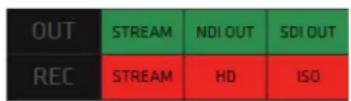
ACTIVITY INDICATORS:
6 indicators providing status info about system processes.
KM-IP4100
OUTPUT indicators color codes:
STREAM - Grey/Green/Orange/Blue = inactive/active/connecting/ active backup URL
NDI OUT - Grey/Green = inactive/active
SDI OUT - Grey/Green = inactive/active

KM-IP6000
RECORDING indicators color codes:
STREAM - Grey/Red = inactive/active
HD - Grey/Red = inactive/active
ISO - Grey/Red = inactive/active
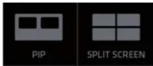
SCREEN LAYOUT SWITCHES
PICTURE IN PICTURE - enables the PIP screen layout functionality
Operating procedure:
- Tap/click the PIP layout switch to select/activate it
If there is no PIP layout setup yet, you need to set it up to be able to use it.
CONNECTED CAM
STUDIO
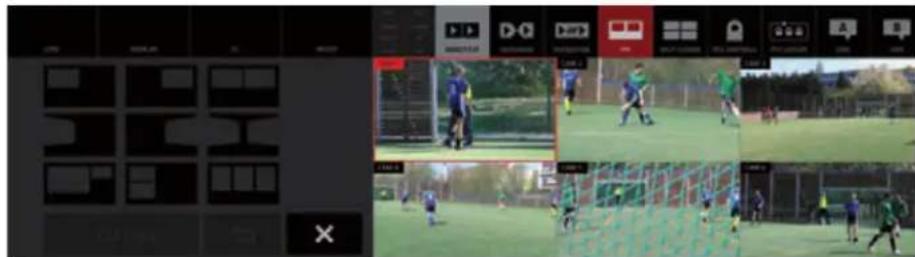
Tap/click and HOLD the PIP switch for over a second to reveal the PIP SETUP window which opens above the PGM monitor
- Tap/click one of the 9 preset templates available - the selected template zooms in (image 1)
- Select the sources for the individual PIP areas by simply tap/click on the source preview monitor
PLEASE NOTE: a source for a PIP can be a live camera, media file, playlist or a replay
The software prompts you to assign a source by highlighting the area in RED that need to be set ...
A... B... C... depending on the number of PIP areas in the selected template (image 2)
Image 1 - Selecting the PIP template
KM-IP6000
Image 2 - Assigning sources to the PIP template areas

KM-IP6000
- When all PIP screen areas are populated/filled with content a red GO LIVE button at bottom activates
- Tap/click the GO LIVE to switch the PIP layout to live PGM
- Tap/click SAVE to save the PIP layout - the saved PIP layout is highlighted in grey in the PIP Templates You can setup another PIP and save it if you wish or exit the PIP SETUP (see point 8b)
- When assigning sources to PIP areas tap/click BACKSPACE to go back a step, press twice to go back two steps and so on
... this way you can modify/clear the existing PIPs
- Tap/click CANCEL do the following:
a: when in the Content selection state - to cancel and go back to the PIP Templates selector to choose another template
b: when in PIP Templates selector - to exit the PIP SETUP window
- The last PIP used in live PGM is assigned to the main PIP SWITCH button in the top section menu for fast, repeated use.
If you wish to select another PIP simply tap/click and HOLD the PIP switch to access the PIP Setup window and select another saved PIP or create a new one.
- To re-assign new content to areas in an already setup PIP template, tap the PIP template, select the area you wish to re-assign and select a new source by a tap/click on it's preview monitor.
SPLIT SCREEN - enables the split screen layout functionality
Operating procedure:
The operating procedure of the SPLIT SCREEN is identical to the of the PIP.
Please refer to the previous page for instructions. The only difference is that now you are working with SPLIT SCREEN TEMPLATES.
Selecting a SPLIT template

KM-IP6000
Selecting sources for the SPLIT areas

KM-IP6000
MIXING MODES:

Tap/Click any of the three switches to select a switching mode with their respective functionality controls.
DIRECT CUT - enables a direct cut between sources
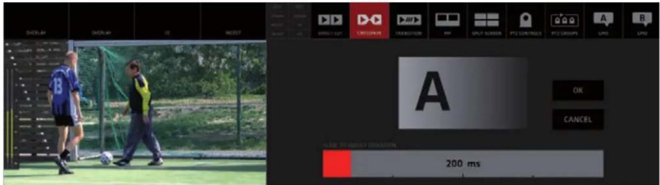
CROSSFADE - enables automated crossfade transition between sources
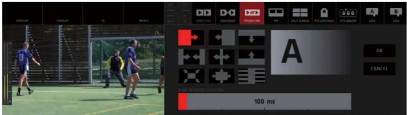
TRANSITION - enables automated wipe transition between sources
Adjusting the Mixing Modes parameters:
DIRECT CUT - Tap/Click the button to select the DIRECT CUT mode. There are no parameters to adjust.
CROSSFADE - [Tap/Click and HOLD] the CROSSFADE button for longer than a second to reveal the CROSSFADE ADJUSTMENT controls. For tap, hold with two fingers.
TRANSITION - [Tap/Click and HOLD] the TRANSITION button for longer than a second to reveal the TRANSITION ADJUSTMENT controls. For tap, hold with two fingers.
Crossfade Duration Adjustment:
The image below shows the CROSSFADE ADJUSTMENT controls window open.
- Use the DURATION BAR to adjust the duration of the crossfade. Slide the red bar to the right to increase the crossfade duration, ...to the left to decrease it.
Or tap/click anywhere on the duration adjustment bar to set a new duration.
- After a new value is set the Preview window above (with letter A) will play a crossfade animation previewing the newly set duration.
- When you are OK with the new duration, tap/click OK to confirm the new duration time value. The CROSSFADE DURATION ADJUSTMENT window closes and from now on all CROSSFADES will be executed with the new duration time value.
The CANCEL button closes the window without any changes to the Crossfade duration.
Transition Template Selection and Duration Adjustment:
The next image below shows the TRANSITION ADJUSTMENT controls window open. It contains 9 Transition Template buttons. Tap/click any of them to select a desired transition.
Use the TRANSITION DURATION BAR to adjust the duration of the transition. Slide the red bar to the right to increase the transition duration, ...to the left to decrease it. Or tap/click anywhere on the duration adjustment bar to set a new duration value.
After a new template is selected and /or new duration is set the Preview window above (with letter A) will play a transition animation previewing the newly set transition template and duration. When you are done with the transition setup tap/click OK to confirm the new transition settings. The TRANSITION ADJUSTMENT window closes and from now on all TRANSITIONS are executed with the new transition and duration time setting. The last selected transition is assigned to the TRANSITION button for fast access. If you wish to select another transition use the above described process again.
PTZ CAMERA CONTROL

Two buttons are:
PTZ CONTROLS - which enable the control of individual PTZ CAMERAS over IP PTZ GROUPS control - which enable the PTZ CAMERA GROUPS control over IP
These 2 functions become available automatically when JVC PTZ cameras are connected to the CONNECTED CAM STUDIO.

GPIO A and B buttons
Two buttons are provided to control / trigger external devices via a GPIO unit. (GPIO = General Purpose Input Output)
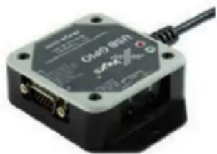
We implemented the X-keys USB GPIO unit which offers 10 configurable ports, 2 of which can be assigned to the 2 buttons in the top menu to send impulses to switch/trigger various external devices.
In CCS we can use it to send TALLY signals over GPIO.
If a camera is switched to LIVE PGM a trigger is sent via a dedicated pin/port to control an on-camera Tally system.
The X-keys GPIO unit connects to the system via an USB port. Any device which can be controlled via GPIO is connected to the X-keys unit via a multi-pin connector.
The setup of the functionality is done in the Settings section.
GPIO unit details: https://xkeys.com/usbgpio.html

natural_image
Close-up of a black electronic device with ports and a cable, no visible text or symbols.X-keys GPIO unit
GPIO PINs assignment when used to control Tally
If the GPIO system is used to control TALLY the pins 1-4 in KM-IP4100 or 1-6 in KM-IP6000 are reserved for the camera Tally control. Switching a camera will trigger the respective pin/port.
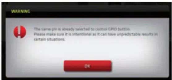
GPIO PINs assignment conflict warning
If GPIO Tally is ON and the user will attempt to assign any of the reserved pins to the GPIO Buttons or if any of the reserved pins is assigned to the GPIO buttons and the user turns on GPIO Tally control a dialog warning boxes will be displayed warning that a PIN assignment conflict is encountered.
The system will still work even with the double assignment of PINs - ports will be opened by switching a camera as well as by activating the GPIO buttons - but the result may be erratic.

NOTE: The X-KEYS GPIO unit is a product sold separately
PGM / CAMERA SWITCHING SECTION
CONNECTED CAM STUDIO
This section features the PGM monitor and the live camera monitors/switches.

KM-IP6000
PGM Monitor
The large PGM monitor on the left is displaying the composite system output - PGM and the AUDIO LEVELS indicator superimposed on top.
The audio level indicator is not part of the composite signal created and broadcast by the SW. It is displayed for information and visual control of the audio output only.
JVC PTZ CAMERA PRESETS and PTZ CAMERA GROUP PRESETS controls display
If JVC PTZ cameras are connected to the system, activating the PTZ CAMERA PRESETS and PTZ CAMERA GROUP PRESETS buttons will display their respective control switches superimposed over the camera preview and PGM preview monitors.
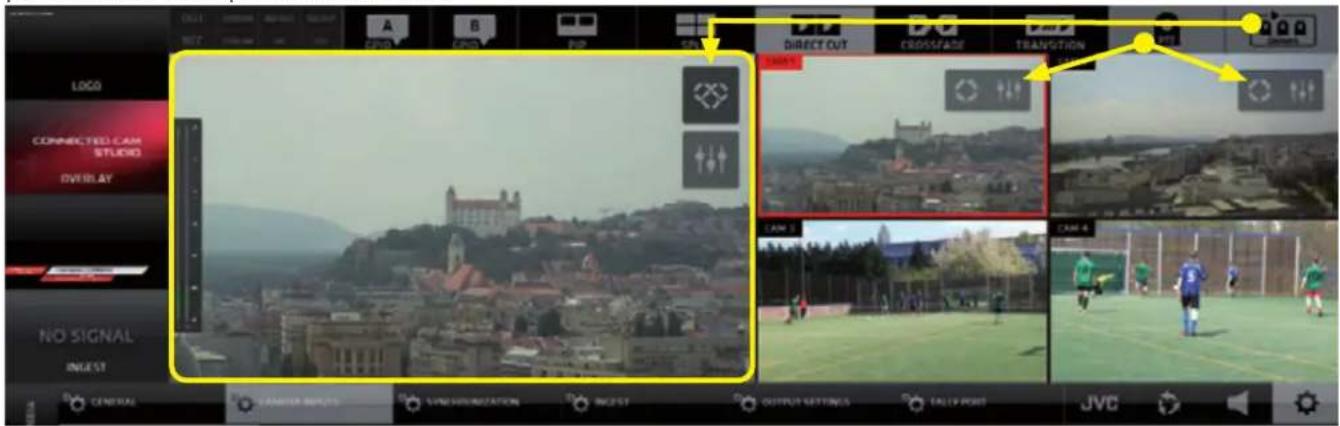
KM-IP4100
Live Camera Monitors
The Live Camera Monitors have several functions:
a, Live camera previews
b, Switches for camera switching - tap/click any of the live camera monitors to switch that camera to PGM.

KM-IP6000
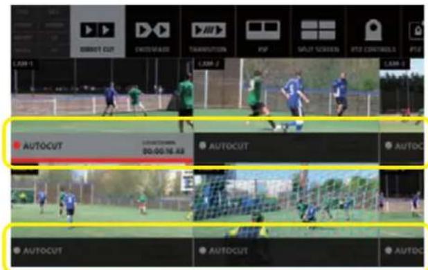
c, Autocut switches display
If other content than a live camera is played in PGM (e.g. a Media file or a Replay) there will be AUTOCUT SWITCHES / BUTTONS displayed at bottom of the CAMERA MONITOR. Tap/click on the AUTOCUT to specify which camera will go to live PGM once the Media/Replay is finished.
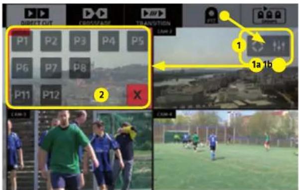
d, PTZ CAMERA PRESETS control switches
If JVC PTZ cameras are connected to the system the PTZ CAMERA PRESETS control switches may be displayed superimposed over the corresponding camera monitors to allow instant access to PTZ camera presets.
Two CONTROL SWITCHES (1) become visible by enabling the PTZ CAMERA button in the TOP MENU.

1a - PTZ CAMERA PRESETS display button
1b - SETTINGS hot-key button to allow quick access to PTZ camera settings in the CMA.
Activating the PTZ PRESETS button (1a) reveals the existing PTZ PRESETS (2) in this PTZ.
Click/tap a Preset button to execute a PTZ camera move to the selected preset.
Click/tap the [X] button to close the presets display.
Click/tap the PTZ CAMERA CONTROL button to hide the PTZ CONTROL SWITCHES and return to a normal camera switching mode.
This section contains all control elements of the functionalities available in CONNECTED CAM STUDIO. It's content displays various controls depending on what is selected. It provides great flexibility and speed of operation.
This part of the GUI is subdivided into two major SUB-sections: A - CONTENT MANAGEMENT AREA (CMA) (marked with letter A) B - SETTINGS AREA (SA) (marked with letter B)
The CMA (Content Management Area) contains 5 TABS on the left that reveal the operational controls for the MEDIA LIBRARY, REPLAYS, PLAYLISTS, OVERLAYS and CG controls.
The SA (Settings Area) has 4 TABS on the top that reveal the control elements for: SYSTEM SETTINGS, AUDIO MIXER, REPLAYS, JVC CAMERA CONTROL.
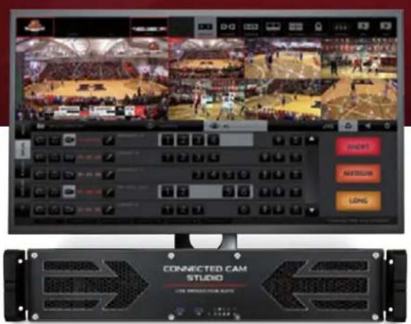
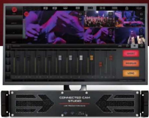
The image below shows the PLAYLISTS controls in CMA and SYSTEM SETTINGS in the SA.

This image shows the AUDIO MIXER controls in CMA and Replay Capture buttons with the TIME/SCORE controller in the SA.

CMA (Content Management Area) - MEDIA Tab
Opens the Media List (ML) pane with all interface elements to operate the MEDIA playback functionality.
The MEDIA pane top bar contains 4 TABS:
A - SELECT MEDIA DIRECTORY - Windows OS access to select the directory which contains your video files
B - OPEN MEDIA DIRECTORY - Windows OS access to manage the selected directory content
C - ADD TO TOP - if new items are added they will be listed at top of the Media File (MF) list
D - ADD AT BOTTOM - if new items are added they will be listed at bottom of the MF list
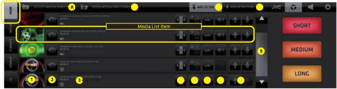
Media List Item
represented by a line in the Media List - it contains all controls to operate and manage the media file
- Media Video Monitor - thumbnail /switch - tap/click it to switch the media file to live PGM.
Media playback is indicated by a red bar moving across the media video preview thumbnail - when selecting content for a PIP or SPLIT area tap/click will assign the media to a PIP/SPLIT area.
-
Media Preview button - tap/click it to preview the media file in the Media Video Monitor thumbnail
The preview progress is indicated by a blue progress bar moving across the Preview button
A media can be cut to live PGM anytime during the preview by a tap/click on the thumbnail media player -
Media file info - contains information about the media file status
-
1st row: name of media file | date created | frame-rate
- 2nd row: entire media duration time | selected duration - when IN/OUT points are set for the media
- 3rd row left: media audio indicator icon
- 3rd row right: large countdown timer displaying the remaining time when the media is playing live
NOTE:
When the media is playing the AUTOCUT function is active on the camera switches allowing you to choose to which camera the system will switch after the media is finished.
Tap any camera switch to cut out of the media playback at any time.
- Media In/Out Points Editor button - tap/click to enter the media In/Out points editor.
The functionality is described in detail on the next page.
- Assign to Playlist button - used to assign the media files to a Playlists
Tap/click the button -> a dialog box appears that enables you to select a playlist (or to create a new one) and add this media file to it. (The procedure is described in detail in the PLAYLISTS section on page 26.)
- Loop button - sets a media file into a loop
- tap/click it several times to cycle through the various loop options
-
Audio Mute switch - mute switch for Media audio
-
Sorting buttons - move Media files up / down in the list
-
Scroll bar - scroll the media files list
MEDIA IN/OUT POINTS EDITOR
Enables you to trim your media file by setting up IN/OUT points for media playback.
The functionality is non-destructive and your physical media files are untouched.
You can reset the IN/OUT points at any time.
Enter the IN/OUT points editor by tap/click on any MEDIA IN/OUT POINTS EDITOR BUTTON in the media file list display - indicated by the yellow arrows in the image below.
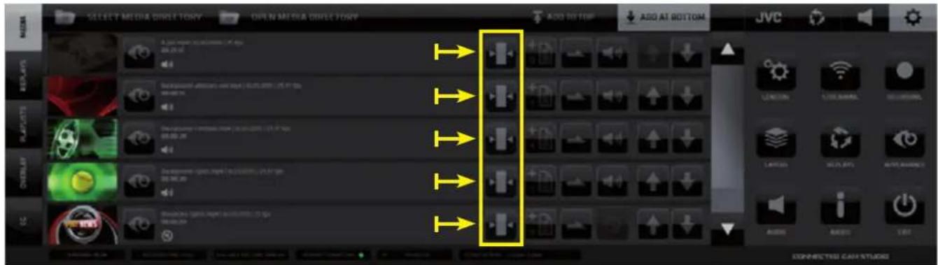
NOTE:
When a media is playing in Live PGM the MEDIA IN/OUT points editor button is disabled for that media file. Out points editing is NOT available.
IN/OUT points control elements functionality
IN/OUT POINTS control elements functionality description
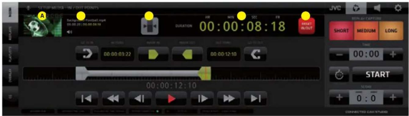
The MEDIA IN/OUT POINTS EDITOR pane contains several elements that enable you to easily and precisely setup the media playback In/Out points to prepare your media for playback in your live production.
1st row - PREVIEW/EXIT/ DURATION/ RESET (left to right)
A, Preview Media Video player
B, media info display - Media file name and entire duration | edited duration
C, media In/Out Points Editor EXIT BUTTON
D, playback duration time of media - between the IN and OUT points.
If no In/Out points are set it shows the entire media duration.
E, RESET In/Out Points BUTTON - clears the In/Out Points and resets media playback to the entire duration of the media file
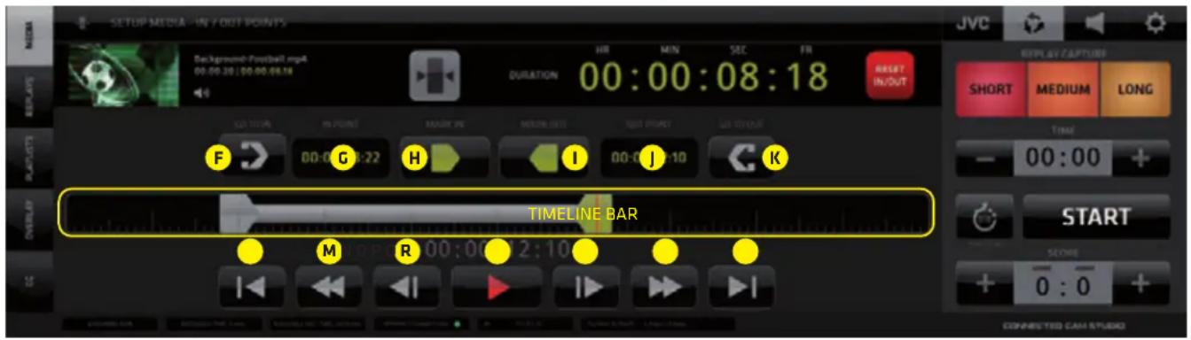
2nd row - IN/OUT POINTS SET/NAVIGATE (left to right)
F - GO TO IN Point - moves the playhead to the IN point location
G - IN POINT Time - displays the IN point time
H - MARK IN Point button - tap/click to set the IN point
I - MARK OUT Point button - tap/click to set the OUT point
J - OUT POINT Time - displays the OUT point time
K - GO TO OUT Point - moves the playhead to the OUT point location
NOTE:
For a manual / keyboard entry of In/Out points DOUBLE CLICK on any of the digit pairs in the IN and OUT DISPLAY and enter a desired numeric value.
3rd row - TIMELINE BAR
Tap/click anywhere on the Timeline Bar to move the playhead to that location. It is indicated by a red line. A numeric display below the Timeline Bar indicates the current time/location of the playhead.
To set the IN or OUT point to that location tap/click the MARK IN or MARK OUT buttons above.
The IN/OUT point is set and the indicator moves to that location, visually identifying the In/Out position.
Use this procedure to set your in out points roughly and fine tune the positions using the 4th row controls.
4th row - VIDEO NAVIGATION CONTROLS (left to right)
L - GO TO FRONT - moves the playhead to the beginning of the media
M - REWIND 1 SEC. - moves the playhead 1 second towards the beginning of the media
N - STEP BACK 1 FRAME - moves the playhead 1 frame towards the beginning of the media
O - PLAY - plays the media in the PREVIEW Video player on top left from the current playhead location
P - STEP FORWARD 1 FRAME - moves the playhead 1 frame towards the end of the media
Q - FORWARD 1 SEC. - moves the playhead 1 second towards the end of the media
R - GO TO END - moves the playhead to the end of the media
MEDIA IN/OUT POINTS SETUP PROCEDURE
- Open the Media In/Out Editor
- Tap/click on the timeline to position the playhead at a desired In Point location
- Use Video Navigation control elements to fine tune the In Point location
- Tap/Click the Mark In button
- Repeat 2. and 3. to locate the Out Point
- Tap/Click the Mark Out button
- Tap /Click the GO TO IN Point button
- Tap /Click the PLAY button to preview the media playback
- Tap /Click the EXIT In/Out Points Editor button to go back to the Media List View.
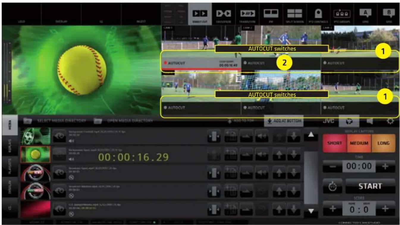
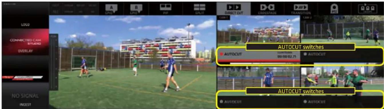
AUTOCUT
At this point we need to explain the AUTOCUT functionality
It is an unique automated switching feature of the CONNECTED CAM STUDIO production SW inherently connected with Media and Playlists playback. It allows you to select a Camera, which will be switched to Live PGM after a Media File or Playlist playback (further: "M/PL") reached its end.
Procedure to operate:
- When a M/PL is switched to Live PGM a darkened area = AUTOCUT SWITCH appears in the lower part of all Live Camera Monitors.
- Tap/click on any of them, to activate it.
After the M/PL reaches its end a camera with the active AUTOCUT switch is automatically switched to Live PGM.
By default, when a M/PL is switched to Live PGM, the AUTOCUT SWITCH of a camera is activated, that was last in live PGM, before the M/PL was played.
Tap/click above the AUTOCUT SWITCH inside the Live Camera Monitor will terminate the AUTOCUT function and normally switch that camera to Live PGM as usual.
A COUNTDOWN TIMER inside the AUTOCUT button indicates the remaining time of the M/PL.
If a M/PL is set to loop, the countdown timer is showing the remaining time of the M/PL currently playing.
KM-IP6000
CMA (Content Management Area) - REPLAYS Tab
CONNECTED CAM STUDIO features an extremely powerful and unique replay system specially designed to make the replays operation fast and easy.
The CMA Replays Menu reveals the REPLAYS LIST of all captured REPLAY SETS.
Each REPLAY SET in the Replays List contains all interface elements to operate the REPLAY functionality.
The REPLAY pane top bar contains 4 TABS:
A -LOAD PROJECT - allows the selection of and existing or creation of a new project
B - OPEN PROJECT DIRECTORY - Windows OS access to manage the project directory content
C - FAVORITES - view only the replay sets that contain a favorite marked replay
D - ALL - view all replay sets captured

Each REPLAY SET contains the following controls buttons:
- Tag editor - name a replay set / add a text note "TAG" for easy identification
- Time of capture - color coded time signature of the captured Replay set
- Replay TAG - display of replay set Tag
- Preview button - triggers the display of video monitors to preview the captured replay set Tap/click a preview to cut the replay of a camera to live PGM OUT
While playing a preview a blue progress bar in the preview button indicates the playhead position
- SRP replay mode - activation switch (Sequential Replay Playback)
- DRCS replay mode - activation switch (Dynamic Replay Camera Switching)
- Camera switches - tap/click any of the camera replay buttons to switch that camera replay to PGM. Replays are cut IN and OUT to PGM with a lead-in and a lead-out animation - called "WIPE"
The Wipes setup and activation is described in the Settings section under REPLAYS/Settings (page 47)
- Sorting buttons - move a set of Replays up and down in the list
- Delete button - deletes a set of Replays from the list and the system
- Scroll Bar - scroll up and down the list
- Replay Capture buttons - used to capture replays of 3 different lengths, which can be set in the Settings/Replays section. Go to page 47. for detailed description.
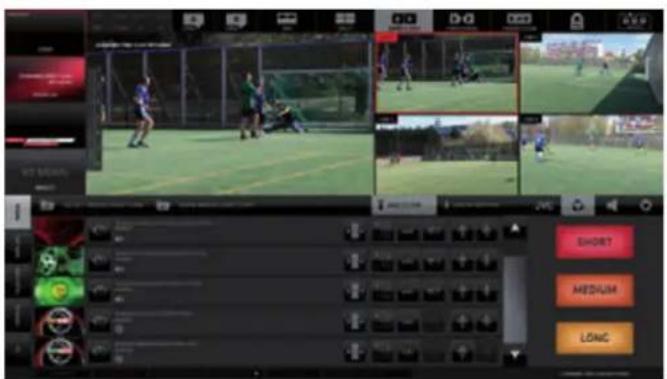
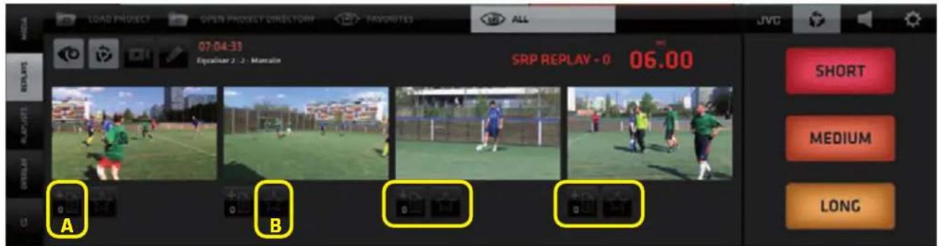
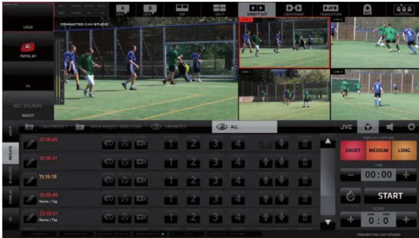
REPLAY CAPTURE
To capture replays the SA REPLAYS TAB needs to be active. It provides access to the REPLAY CAPTURE BUTTONS [A] or Replay Capture Buttons combined with the TIME/SCORE CONTROLLER [B]
(provided the controller is turned on in CG/ Timing Options Tab) that allows time/score control as well as replay capture.
REPLAY CAPTURE BUTTONS
1. SHORT
triggers the capture of 3, 4 or 5 sec. replays in selected 4 cameras (the length can be set in REPLAY SETTINGS - default is 3 sec.)
2. MEDIUM
triggers the capture of 6, 8 or 10 sec. replays in selected 4 cameras (the length can be set in REPLAY SETTINGS - default is 6 sec.)
3. LONG
triggers the capture of 10, 15 or 20 sec. replays in selected 4 cameras (the length can be set in REPLAY SETTINGS - default is 10 sec.)
A

SA - Replay Capture buttons
B
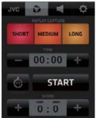
SA - Replay Capture buttons and Time/Score Controller

KM-IP6000
Replay Capture and Playback procedure
-
Activate the REPLAY TAB on top of the SA to reveal the REPLAY CAPTURE buttons in SA and open the REPLAYS LIST in the CMA. In a new project there are no replays captured yet, hence and empty list.
-
To capture a REPLAY SET tap/click one of the REPLAY CAPTURE buttons in the SA. A Replay Set is a set of 4 replay files (one for each camera). It's listed as one line in the REPLAYS LIST.
Each REPLAY SET (outlined yellow) contains the following elements:
A - EDIT REPLAY NAME button - push and type to name the replay set
B - TIME STAMP and REPLAY NAME - time and name display
C - PREVIEW button - enter the Replay Preview pane
D - SRP REPLAY MODE button - turn SRP Mode ON/OFF
E - DRCS REPLAY MODE button - turn DRCS Mode ON/OFF
F - REPLAY CAMERA buttons - replay playback for each camera
G - SORTING buttons - move a replay set up/down in the list
H - DELETE REPLAY button
The REPLAY LIST also has 2 SORTING TABS on the top:
J - FAVORITES - view only those Replay Sets that contain a replay marked as FAVORITE K - ALL - view all Replay Sets

KM-IP4100
REPLAY MODES
CONNECTED CAM STUDIO features a very unique and extremely efficient, easy-to-use replay system that doesn't require special training or an extra operator.
It offers 3 different MODES to work with replays, that provide many creative possibilities.
- NORMAL MODE
- SRP - SEQUENTIAL REPLAY PLAYBACK MODE
- DRCS - DYNAMIC REPLAY CAMERA SWITCHING MODE
NORMAL mode - a replay is switched to PGM by a tap/click on any of the numbered replay cam buttons.

KM-IP4100

SRP - SEQUENTIAL REPLAY PLAYBACK mode - allows to play a sequence of replays.
- Tap/Click the SRP MODE ICON to activate the SRP MODE (outlined in yellow)
The numbered replay camera buttons become outlined to indicate the active SRP MODE.

KM-IP4100
- Tap/click any of the numbered replay camera buttons to start the playback of a replay sequence.
The REPLAY PREVIEW pane opens and the replay playback of the selected replay camera is indicated by a blue progress bar above the replay video monitor. Click any other video preview monitors you wish to add to the sequence. All this way selected replays will play in a sequence in the same order as selected. The replay playback progress is indicated by a blue progress bar above each replay video monitor. Additionally a numeric display in the top right of the replay preview pane indicates its remaining time.
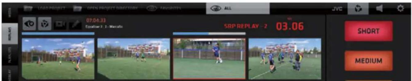
KM-IP4100
- Tap as many replays as you wish to add to the presently playing sequence.
A replay that is already finished - indicated by a blue bar above - can be added to the currently playing sequence again by tapping its video monitor again. Its bar turns grey and the replay will be added to the replay sequence again.
At this point you can either CLOSE the Replay Preview, MARK a replay as FAVORITE or ASSIGN a REPLAY to a PLAYLIST to create a REPLAY HIGHLIGHTS PLAYLIST - described further down on the next page.

CLOSING REPLAY PREVIEW
Tap/click the PREVIEW ICON in the Replay Set to close/open the replay PREVIEWS pane with replay preview monitors. The previews loop indefinitely to give a good overview of their content.
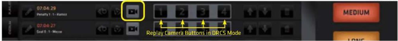
DRCS - DYNAMIC REPLAY CAMERA SWITCHING mode
Allows switching camera angles during replay playback. Click the DRCS MODE ICON to activate the DRCS MODE. (outlined in yellow) numbered REPLAY CAMERA buttons group in a block to indicate the DRCS MODE.
- Tap any of the camera buttons to start the DRCS replay playback in PGM.
KM-IP4100
The REPLAY PREVIEW opens immediately in the CMA to reveal the Replay Preview Monitors. The DRCS replay playback is indicated by a BLUE PROGRESS BAR and the red text: "DRCS REPLAY" above.
KM-IP4100

- While the first replay is playing in the PGM tap/click the replay preview monitors to switch camera angles just like switching cameras in real time. The replay preview monitor of a replay currently in PGM is outlined in RED for visual control.
A COUNTDOWN TIMER is provided displaying the remaining time of a replay. Once the replay is finished a live camera is automatically switched to PGM via AUTOCUT (described on next page).
FAVORITES and REPLAY HIGHLIGHTS
In the open REPLAY PREVIEW two more buttons are available below the replay preview monitors: A - Add Replay to Playlist - adds a replay to a playlist to create a Highlights sequence in Playlists B - Favorite - marks a replay as Favorite - used for FAVORITES VIEW in the Replays List.
KM-IP4100
SLOW MOTION REPLAY PLAYBACK / FREEZE FRAME
During the replay playback SLOW MOTION functionality is available. Default replay playback motion ratio is 50% of original speed. Use the following keyboard shortcuts for Variable speed and Freeze frame:
[X] - hold to slow down replay playback to 20% of the original speed
[C] - hold to speed up replay playback to 100% of the original speed
[Z] - push to freeze frame, push again to continue replay playback
All replay playback parameters are fully adjustable in the SETTINGS / Replay Settings section.
DELETING REPLAYS
Replay Sets are stored internally as time-stamped files for each camera separately.
Deleting a Replay Set is a destructive operation, which physically erases the files from storage.
AUTOCUT IN REPLAYS
Allows users to select a live camera, that will be switched to PGM automatically, after a Replay ends. When a replay is switched to Live PGM the AUTOCUT SWITCH appears on top of the lower portion of all Camera Monitors. Tap/click to activate it on any camera.
After the replay ends the camera with the AUTOCUT ON will be automatically switched to Live PGM.
The AUTOCUT functionality is described in detail on page 19.
KM-IP4100
NOTE: By default, the AUTOCUT SWITCH of that camera is activated, which was live in PGM before the Replay was switched.
WIPES
Short Lead-In / Lead Out animations used in the Replay system as transition to enter and exit the Replay. The users can create these animations themselves to enhance the visual appeal of their productions. It is a well accepted, unobtrusive way to introduce commercial content, sponsor logos etc. to the production which can become a source of extra revenue for the production. Exact Wipes usage statistics are provided for monetizing purposes.

KM-IP4100
NOTE:
A choice of a single wipe, a wipe sequence or a random shuffle mode can be set for the use of Replay Wipes.
Wipes format:
FLV/MOV animations with transparency.
The switch to and from a replay is executed 1 sec. after the wipe start exactly.
To cover the switch to a replay it is best practice to create an animation with a full frame graphic at 1 sec.
A detailed tutorial on Wipes construction is available at this link:
http://support.streamstar.com/759260-Replay-Wipes---Usage-and-Settings
NOTE: By default, wipes are used when entering and exiting the replay system only. When switching from replay to another replay a 10 frames crossfade is used. The user can override this setting by turning the functionality off in Replay settings.
CMA (Content Management Area) - PLAYLISTS Tab
Opens the PLAYLISTS pane with control elements to operate the PLAYLISTS functionality. Playlists (PL) are virtual collections of MEDIA files or REPLAYS assembled in a list for continuous playback. Each PL can be expanded with the EXPAND button to reveal its content. Each PL Item contains a set of control elements to control its behavior in the Playlist.
The PLAYLIST pane top bar contains 2 TABS:
A - LOAD PROJECT - allows the selection of and existing or creation of a new project
B - OPEN PROJECT DIRECTORY - Windows OS access to manage the project directory content
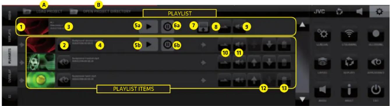
The PLAYLIST pane contains a list of PLAYLIST ITEMS with the following controls buttons:
- PL Switch - thumbnail/video player/monitor of the entire playlist tap/click it to cut the Playlist to PGM, when live in PGM tap/click it again to cut out of PGM
- PL Content Preview/Switch - thumbnail video player of each item in the playlist tap/click it to cut to PGM. When being played live in PGM tap/click to cut it out of PGM.
- PL info - info text about entire PL - name, duration, file count
- PL item info - PL item info - media file name, duration, counter
5a. PL Pause/Continue / 5b. PL item Pause/Continue - Pause/Continue the playback of a PL resulting in a MF freeze frame. To continue to play the MF push the Pause/Continue button (5a/5b)
6a. PL Autopause / 6b.PL Item Autopause - if ON switching out of the PL by a camera switch pauses the MF automatically at the frame when it was switched out of the PGM. To continue to play the PL push the Pause/Continue button (5a/5b) - PL Expand/Collapse button - tap/click to expand a playlist to view/manage it's content
- PL/Loop button - set the loop playback of the entire PL On/Off
- PL Audio On/Off button - entire PL audio on/off/unavailable
- PL Item Loop button - set the loop playback of the PL item On/Off
- PL Item Audio On/Off button - individual PL item audio On/Off/Unavailable
- Sorting buttons - move a Playlist or individual item up and down in the list
- Delete - delete a PL item or the entire playlist if the PL is closed - DELETE icon is in top line
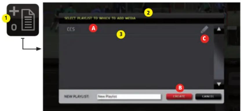
Playlist Management
To assign a media item to a Playlist:
- Go to MEDIA or REPLAYS and locate the ASSIGN TO PL button
- Tap/click on it reveals a dialog box that enables you to:
A - select a PL
B - create a new PL
C - edit PL name
- Tap/click a PL in the dialog box list to assign the Media/Replay to that PL
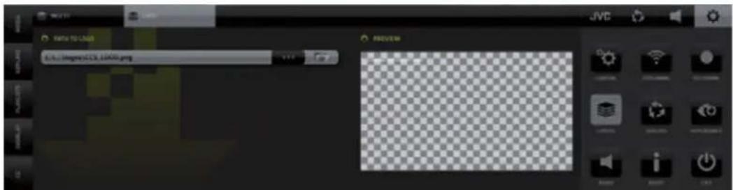
CMA (Content Management Area) - OVERLAYS Menu Tab
The OVERLAYS enables the insert of pre-rendered graphics into your live PGM.
Typical usage is info graphics, bumpers, stingers, advertisements, pop up promos and similar.
Supported files: .PNG .FLV .MOV - all with transparency / alpha channel
(Supported .MOV files specs on page 46)
The OVERLAYS controls are accessed via the OVERLAYS TAB within the left side menu in the CMA.
OVERLAYS LAYER SWITCH ON/OFF
KM-IP6000

OVERLAYS Operation Procedure:
- Tap/click the OVERLAYS TAB in the left side menu bar of the CMA to display the OVERLAYS content.
- Specify the directory containing your Overlays files using the SELECT OVERLAY DIRECTORY tab located in the CMA top menu bar.
- Tap/click the LOAD ALL button to load the first 10 files in the specified Overlays directory into the 10 provided memory slots. A PREVIEW THUMBNAIL of each graphic is displayed in the slot.
Each slot can also be loaded individually using the drop-down selector button on top of each slot. - To select a graphic to be inserted into live PGM tap/click a Slot. It's outlined in RED when selected.
- To insert the selected Overlay into PGM Tap/click the OVERLAYS LAYER switch on top left side in the Production Layout Section.
NOTE: Eatively if the OVERLAYS LAYER SWITCH in the Production Section on top left is active, you can switch the Overlay graphics directly by tapping the thumbnail previews in the Overlays pane in the CMA.
The CONNECTED CAM STUDIO Keyboard Shortcuts for the Overlay slots are marked in BLUE. (The keys Q - T for the top 5 slots and Y-P for the bottom 5 slots)
CMA (Content Management Area) - CG Menu Tab
It contains a list of CG OBJECTS with all control elements to operate the CG functionality.
The CHARACTER GENERATOR - CG enables you to insert real time generated graphics to your live PGM.
There are 3 types of CG objects that can be created within the CONNECTED CAM STUDIO CG system:

- Text CG - 5 layers of texts positioned over a graphic background file with transparency.
Each layer can be individually positioned and formatted to create a complex CG composite.

- Crawl CG - animated text layer positioned over a graphic background file with transparency.
It can be formatted and looped to crawl across the screen in various directions and speeds.

- Dynamic Timer/Score CG - a combination of text and dynamic data layers, controlled by
Live controller. Score, timer and game period layers and a graphic background layer, all individually formatted and positioned to create sophisticated live sports graphics CG Objects.
CG LIST CONTENT - The CG LIST is accessed via the CG TAB in the left side menu of the CMA.
The TAB BAR on the top of the CG pane contains 6 TABs that provide access to the following:
A - CG PROJECT SELECTION - select a CG project to load into the CG List
B - NEW TEXT - creates a new TEXT CG object in the CG List
C - NEW CRAWL - creates a new CRAWL CG object in the CG List
D - NEW TIMER SCORE - creates a new TIMER/SCORE CG object in the CG List
E - TIMING OPTIONS - access to Timing Options settings for the Timer/Score CG objects
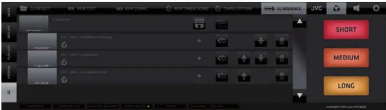
F - CG SEQUENCE - Create sequences of CGs that will play automatically one by one or triggered manually
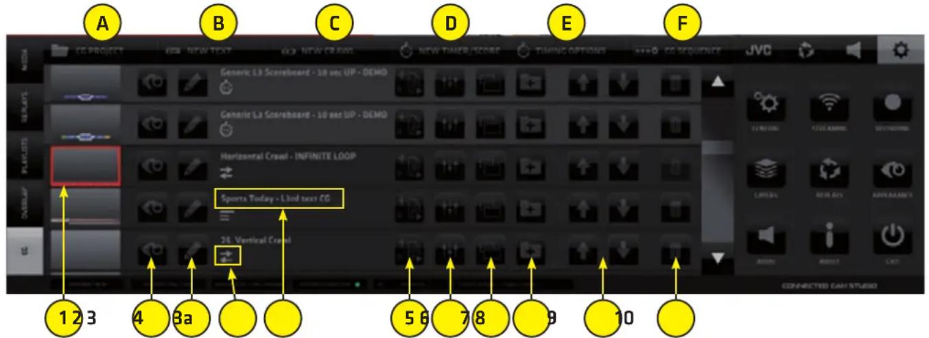
Each CG object in the CG List contains the following control elements for that particular CG object:
- THUMBNAIL - a small preview of the CG that also functions as a SWITCH to select the CG item
- PREVIEW - play button to preview the CG animation inside the THUMBNAIL
- EDIT CG NAME - button opens the CG NAME FIELD (3a) to allow typing/editing of its name
- CG TYPE ICON - indicates the Type of CG Object in the CG LIST - Static text, Crawl, Dynamic timer/score NOTE: Timer/Score CG Objects are visually differentiated by a lighter background color
- ADD TO CG SEQUENCE - used to add the CG Object to CG sequence (page 33)
- SETTINGS - access to the Settings Editor to setup the CG Object's parameters
- DUPLICATE - creates a duplicate of this CG Object in the list so variations can be made easily
- ADD CG TO CG PROJECT - add the CG object to a CG project which can be loaded/exported/imported for better organization of CGs and use on different CONNECTED CAM STUDIO systems
- SORTING - arrow buttons to move CG Objects in the CG List up/down to organize the CG List
- DELETE - delete a CG Object from the CG List
Adding a CG to a CG Project / Creating / Managing CG Projects
CONNECTED CAM STUDIO
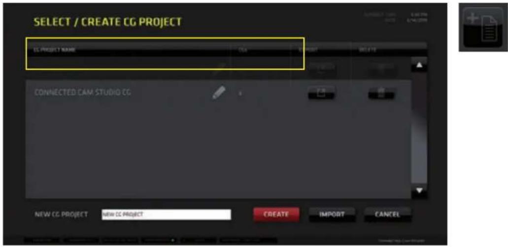
CG Operation Procedure:
A. Tap/click the CG TAB in the left side menu bar of the CMA to display the CG list pane.
B. Specify which CG project to use
- click/tap the CG PROJECT Tab in the top bar of the CMA
- select the project from the projects list window
C. Tap/click the CG thumbnail in the list to select it - outlined in red when selected
D. Switch the CG Layer to live PGM using the CG switch in the LAYERS section.
KM-IP6000

NOTE: The CG Object TYPE is indicated by the CG Type ICON under the CG Name.
TIMER SCORE CGs are also highlighted in the CG LIST with a brighter gray background color for quick visual differentiation.
CG OBJECT CONSTRUCTION
All CG objects are constructed from separately controlled layers. Depending on the type the CG Object will have different layers that need to be setup.
All CG Objects contain a GRAPHIC BACKGROUND layer plus several other - either editable or dynamic text layers that are positioned on top of the background layer.
All layers are combined to create a composite CG Objects that can be used in your productions.
CG PARAMETERS EDITING
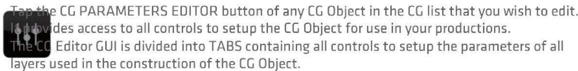
- BACKGROUND Layer
Contains the controls to setup the background graphic for all the other TEXT layers placed above. Supported file formats are: - .FLV and .MOV for animated backgrounds with transparency support (supported .MOV files specs on page 46) - .PNG for static graphics (with transparency support)
• TEXT and CRAWL Layer
Allows to type/paste/edit the text content and control its parameters.
• DYNAMIC TEXT Layer
Used in the Timer/Score CG Objects only. Its content is controlled by a TIME/SCORE controller that allows to increase the score, the game period or it is a running timer measuring the time of the game.
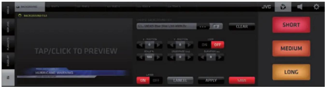
BACKGROUND Layer parameters setup
- CHOSE BACKGROUND FILE - select a graphics file from the Windows OS
- CLEAR - clears the selection of a background file
• X-POS, Y-POS - position the graphics file using the coordinates controls - LOOP - loop on/off for the graphic/animation file
- SCALE, CROSSFADE - set respective parameters for the BACKGROUND layer
• DURATION - determines the time duration for the file to be displayed
| NOTE: | It determines the overall time the background file is displayed also when the LOOP is ON. Set the Duration to 99999 if you want the file to be displayed for a very long time. Use keyboard to type it in the box. |
- Tap/click the PREVIEW monitor to preview the modified CG Object
Buttons at bottom:
- LAYER ON/OFF - switches the layer visibility in the CG Object composition On/Off
- CANCEL - aborts the editing and exits the editor -> go back to the list of CG items
- APPLY - applies the changes you made to the CG Object
- SAVE - saves all changes and exits the editor -> go back to the list of CG items.
TEXT Layer parameters setup
- Edit/Type the text content in the text field
- Format the text using the provided controls - Font, Size, Line Spacing, Style, Opacity, Alignment in a usual text editor way.
- Setup the text position using the X-POS, Y-POS, Text Block Width, Text Block Height properties
- Setup the text animation using the In-Time, Out-Time, Crossfade properties
- The LAYER ON/OFF, CANCEL, APPLY and SAVE buttons function the same way as described earlier.
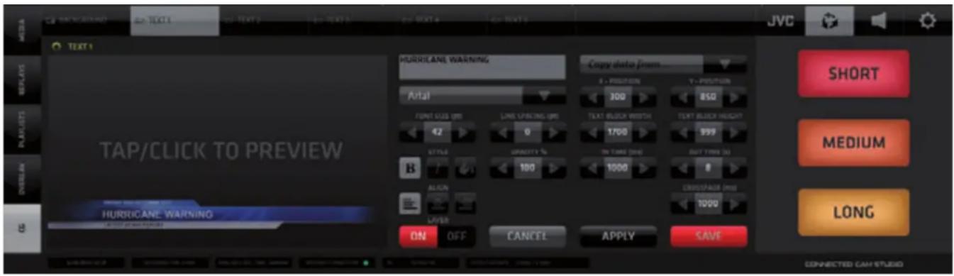
NOTE:
X/Y POSITION parameters define the coordinates of the TOP LEFT corner of the text block within the video frame. The TEXT BLOCK WIDTH and HEIGHT parameters define the width and height of the whole text block calculated from the X/Y coordinate. (E.g.: If the X coordinate =0 and TEXT BLOCK WIDTH = 1920 px it means the text block is set to the full width of the frame)
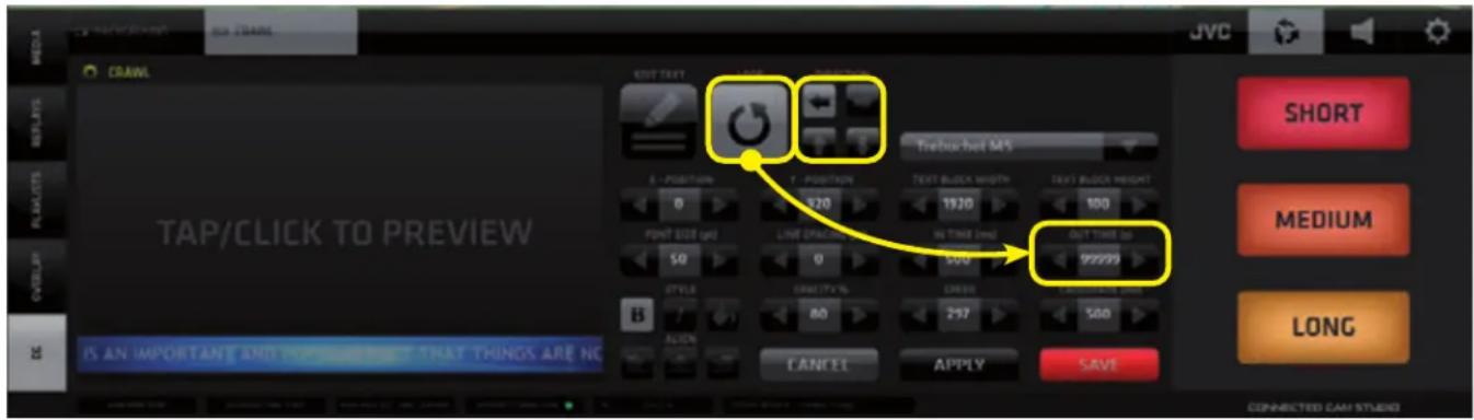
CRAWL Text Layer parameters setup
The procedure is identical to editing a regular text layer with a few additional settings:
- SPEED - set the speed of text movement
- DIRECTIONAL BUTTONS - set the direction of the text movement
- LOOP - turn a loop of text movement on/off
- EDIT TEXT - enter a separate EDIT CRAWL TEXT pane to allow longer text edits. All the other controls function the same way as already described.


CRAWL DIRECTION and LOOP parameters setup
- Use the LOOP button to loop the crawl text.
- Use the CRAWL DIRECTION buttons to specify the crawl direction.
NOTE: The loop is only active for as long as set by the OUT TIME parameter which has priority. The OUT TIME setting will terminate the crawl loop playback. To loop the crawl text indefinitely you need to set the OUT TIME to a value of 999 or larger.
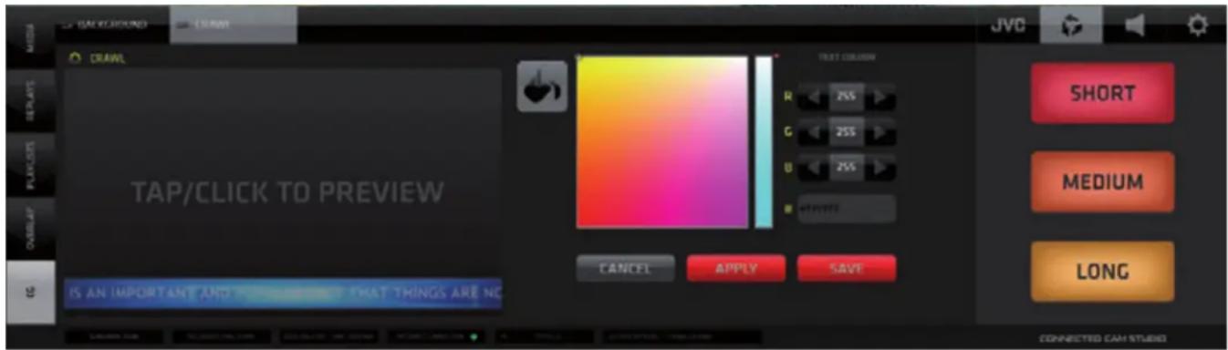
TEXT LAYER COLOR parameters setup
the BUCKET Icon in the STYLE group of icons. The COLOR EDITOR pane opens ick inside the color selector or enter the new color RGB values numerically he APPLY button to view the new text color in the PREVIEW monitor
- Once you decide on the new color push the SAVE button to save the setting. The color editor closes and the CG editor is displayed with text in new color.
- Once you are done with all edits push SAVE to re-render the CG and exit to the CG list view
NOTE:
CONNECTED CAM STUDIO provides several examples of ready-made CG items to help you get started working with the CG system quickly. We recommend to duplicate any CG Object before you start editing it's parameters so the original configuration is preserved for reference.
CG SEQUENCE
CONNECTED CAM STUDIO
CG Sequences
Create and play CG sequences in the same way as you do with Media Files in a Playlist.
Add a CG to a Sequence by pushing the ADD TO CG Sequence button and select/create a CG Sequence

CG Sequences Tab
Navigation and operation is identical to Playlists however CG objects can be constructed so that the are endless. Therefore You need to keep that in mind when creating and playing a CG Sequence. It needs user interaction to advance the CG Sequence when an endless CG is in the Sequence otherwise and endless CG Object will just stop and remain unless it is manually advanced. This needs to be understood to take good advantage of this functionality.
TIMER/SCORE CG Objects
This type of CG Object allows you to create live sports graphics dynamically controlled via the TIME/SCORE CONTROLLER. It is revealed via the [0:0] tab in the SA MENU and/or the TIMING OPTIONS Tab found in the CG Tab of the CMA Left Side Menu.
The controller is displayed within the SA (Settings Area) to allow simultaneous operation of the live game graphics controls along with operating other functionalities of the SW.
The controller offers SCORE and a GAME TIME controls with various options.
Detailed description is provided in the TIMING OPTIONS TAB section on the next page.

TIMER/SCORE CG Object - Layers Setup
All TIMER/SCORE CG Layers are setup in exactly the same way as the layers in a regular TEXT CG with the difference that there are no input fields for the dynamically or automatically triggered text fields. The default values for those are displayed when setting up to allow for positioning and formatting. The actual values will be controlled during the live game using the TIME/SCORE CONTROLLER described above.
TIMER/SCORE CG Layers:
BACKGROUND - a graphics file used as background for all the text layers placed above it
TEAM HOME and TEAM AWAY - regular text layers to be filled in by user
SCORE HOME and SCORE AWAY - dynamic layers to indicate the current score
DELIMITER - regular text layer to be used as a separator between the score indicator digits
PERIOD - automatic layer indicating the current game period
CLOCK - automatic layer - running timer display
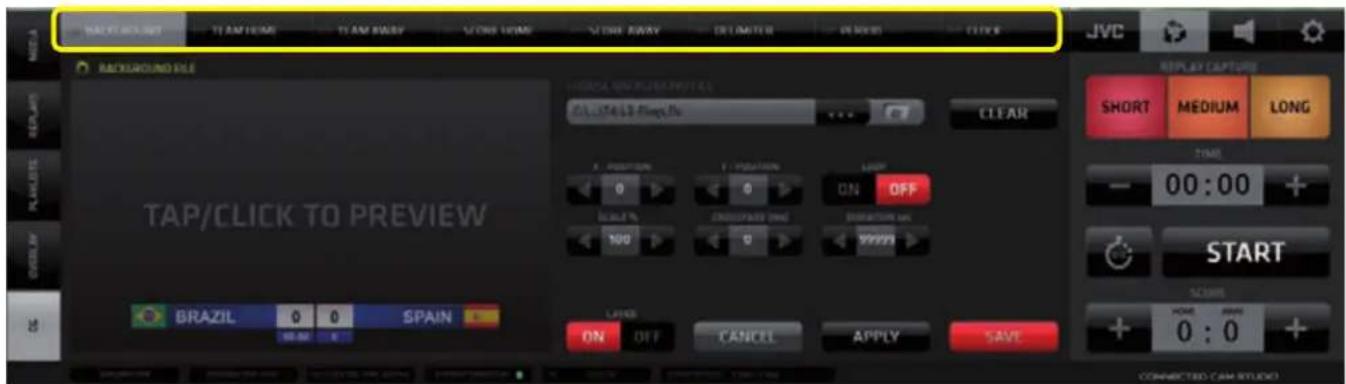
Combining these elements allows the creation of effective live sports graphics. Examples are provided with the installation of CONNECTED CAM STUDIO free to be used in your productions. Custom graphics can be used by selecting your own graphic for the background layer and setting up text layers on top.
This is where the dynamic layers data output logic is setup. The output of the TIMER/SCORE CG Object may vary significantly depending on how the various parameters in this pane are set. Please read this section carefully and familiarize yourself with all the settings and their effects on the display of the system to avoid unexpected or confusing results. Once you understand it thoroughly it will serve you well.
CLOCK Parameters Setup
- START TIME - use the +/- buttons to set the starting time for the time counter or type a time value in the center field manually.
This will be the time value the timer will START at match beginning.
NOTE: Inserting a value here will not yet affect the actual state of the counter in the controller and the CG display until you press the SET TIMER button described further down.
- COUNTING - choose a time counting method. [ + ] counting UP ... [ - ] counting DOWN
NOTE: Be aware that if the COUNTING Method is set to [-] DOWN, the Start Time field needs to be set to a value allowing a Time Countdown to actually take place!
- TIME DISPLAY - choose whether the time counter is to display time per MATCH or per GAME PART
NOTE: Be aware that this parameter setting will have dramatic effects on the actual time displayed. The displayed time will be affected by the Counting Method and the Start Time.
If the Counting method is set to [ - ] Countdown, and Time Display is set to PER MATCH the Start Time field needs to be set to a value that covers the entire match.
If the Time Display is set to PER GAME PART hence the Start Time field needs to be set
to the duration of a Game Part. The clock has to be stopped manually after each game part.
- SET TIMER - SET TIMER red button will actually insert the time value in the START TIMER field into the LIVE TIME COUNTER in the CONTROLLER and in the CG Output.
- CANCEL will undo changes in the Start Time Field to a previously set value which was confirmed by the SET TIMER button.
- RESET TIME - will instantly reset the TIME value in the Controller as well as in the CG Output to the value specified in the Start Time field of the Clock setting.
It will also STOP the clock and timer display.

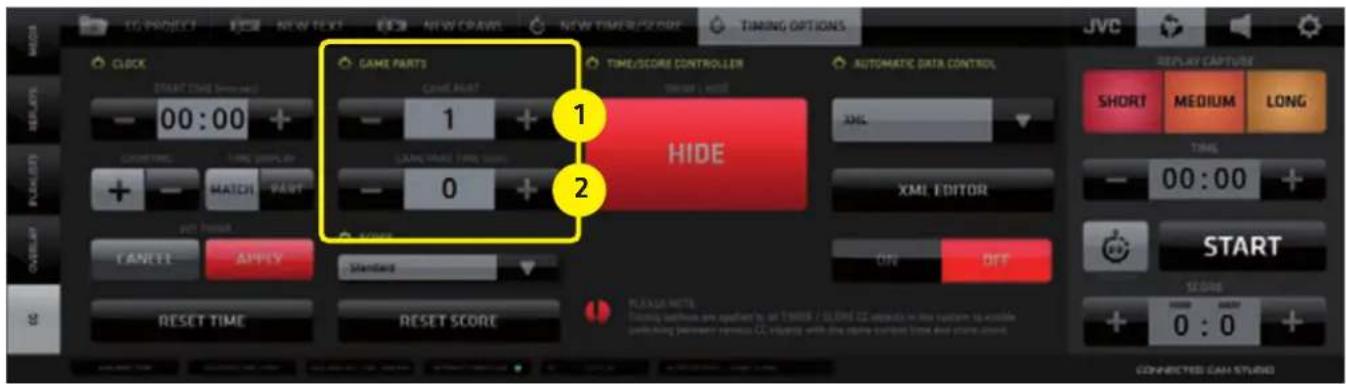
GAME PARTS Parameters Setup
- GAME PART - use the +/- buttons to set the Number of Game Parts in the game.
NOTE: This value needs to be set if you wish to count time by Game Parts.
- GAME PART TIME - use the +/- buttons to set the Duration of an individual Game Part alternatively you can type in the numeric value directly
NOTE: This value needs to be set if the Time Display Clock parameter is set to Game PART. The clock has to be stopped after the game part. When it is started again at the beginning of a new Game Part it will start counting the set Game Part Time again regardless of when it was stopped - thus allowing to count the time of a new Game Part from its start.
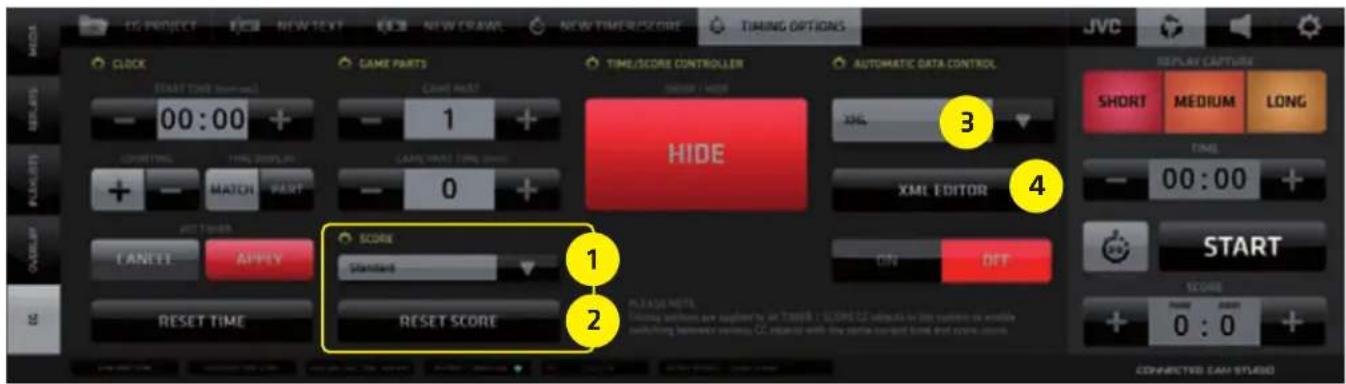
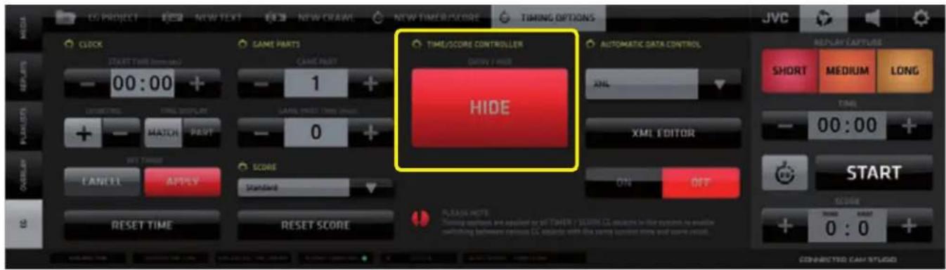
SCORE Parameters Setup
- SCORE TYPE - drop down menu selector allowing the choice of a scoring method.
At the moment a general scoring method is available. Scoring methods for other sports with a different scoring scheme (e.g. Tennis, Baseball) will be available in a future versions of the SW. - RESET SCORE - resets the score to the default value of "0 : 0"
- AUTOMATIC DATA CONTROL - selection of external data source
- XML EDITOR - setup of the incoming XML data
NOTE:
Timing options parameters are applied to all TIMER/SCORE CG Objects in the entire CG system to enable switching of various CG Objects with identical values = synchronized data.
Push the big SHOW/HIDE button to reveal / hide the Live TIME/SCORE CONTROLLER in the SA to allow for live game control / manual control of the data in the dynamic layers of Timer/Score CG Objects.
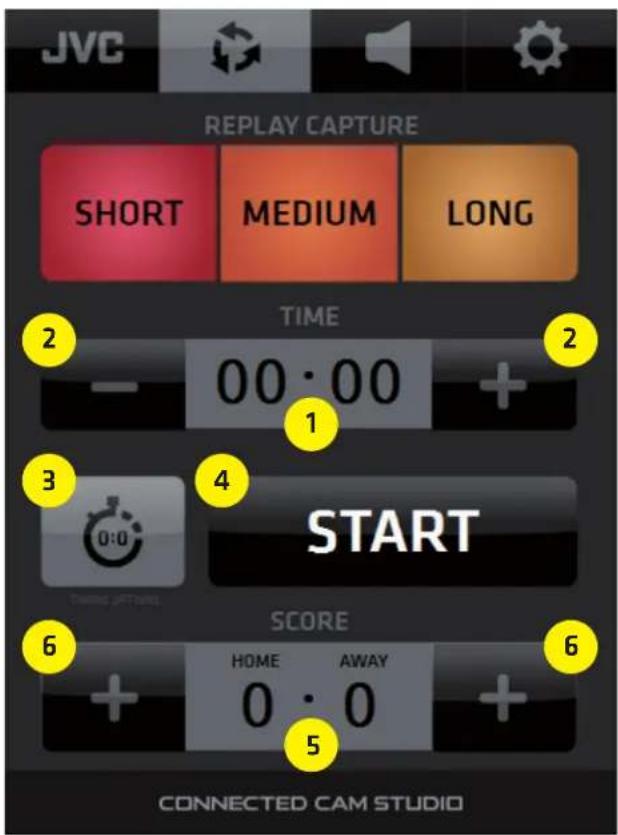
TIME/SCORE CONTROLLER functionality
- TIME Display
indicates the current time based on the Start Time settings in the Timing Options Pane.
- TIME ADJUST +/- buttons
to both sides of the TIME display allow for manual time correction
- TIMING OPTIONS HOT KEY
SHOWS/HIDES the Timing Options pane
- TIME START/STOP button
Starts or Stops the clock
-
SCORE INDICATORS
-
SCORE ADJUST buttons
Increase the score by pressing the [ + ] on either side. Press and hold the button for over 1 second turns it to a negative icon [ - ] allowing to decrease a score. Press and hold again to revert to [ + ]
NOTE:
Controller entries are applied to all TIMER/SCORE CG Objects in the entire CG system to enable switching of various CG Objects with synchronized data.
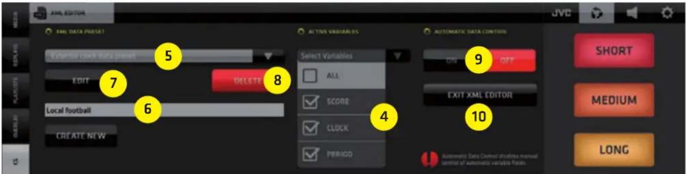
AUTOMATIC DATA CONTROL
The internal Timer Score CG systems dynamic data can be controlled from external sources via XML data.
Procedure:
- Select the source of XML data by the drop-down selector box.
It can be either an XML file or a separate custom made application that is capable of sending pre-formatted XML data for the CG system over IP. In the screenshot below there is an app called "Tblkontrol" which was created by a user and is shown just as an example.

-
Select XML to obtain the XML data from a local XML file that is received by CONNECTED CAM STUDIO system and periodically updated from an external source.
-
To setup the XML data structure conversion push the XML EDITOR BUTTON (explained below).

- Select the variables you wish to control - 3 types are within the internal CG system (score, clock, period)
- Select a preset of XML data conversion to use
- If there is no preset yet available, create a new one by typing in the name and click CREATE NEW. Then select the preset (as in point 5.)
- If you wish to edit the preset click EDIT to enter the XML data conversion setup
- If you wish to remove an existing preset click DELETE
- Once you are done with the XML preset setup click ON to activate the external data control
- EXIT the XML EDITOR
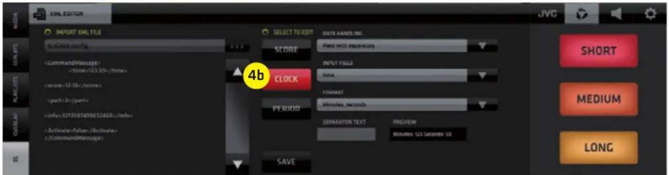
EDITING AND XML PRESET
Clicking the EDIT button in step [7] on the previous page you will enter the XML PRESET SETUP.
- Click the file selector to select the XML file to be used for external data control
- The XML file content will show in the scroll window on the left.
- Select the Variable that is to be controlled by the data within the selected external XML file on the left
4a. Variable SCORE setup - active
Setup its parameters to convert from the external XML file data structure
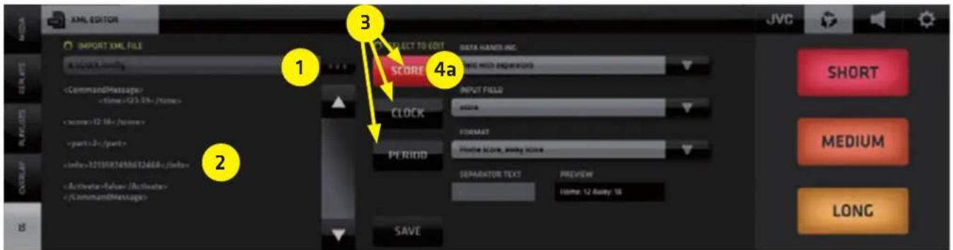
4b. Variable CLOCK setup - active
Setup its parameters to convert from the external XML file data structure
4c. Variable PERIOD setup - active
Setup its parameters to convert from the external XML file data structure
- After setting up the XML data conversion click SAVE to store the XML preset.

NOTE:
Expert skills and understanding of the XML data format and its data structure is absolutely required to be able to set this up correctly. Please consult an IT specialist in case you need assistance setting up the external data control of the CG system dynamic data.
SA - SETTINGS AREA MENU Tabs
Contains 4 Tabs revealing user interface elements that provide access to:
- SYSTEM SETTINGS
- AUDIO MIXER
- REPLAYS
- JVC CAMERA CONTROLS

NOTE:
For a good understanding of all the operating procedures and SW functionalities covered in the SA MENU TABS it is important to learn about the System Settings and their implications on the system performance first. Therefore we'll go through it in right to left order.
The SA Menu Tabs change the content of both the SA and CMA as follows:
1. SYSTEM SETTINGS Tab
SA - System Settings buttons CMA - no change from previous
2. AUDIO MIXER Tab
SA - Live TIME/SCORE controller * CMA - AUDIO MIXER in the CMA
*) Access to the time/score controller in the SA has operational priority it is displayed for as long as possible and is hidden only when it is unavoidable.
3. REPLAYS Tab
SA - Replay capture buttons with Live TIME/SCORE Controller CMA - Replays List
4. JVC CAMERA CONTROLS Tab
SA - camera selection buttons CMA - JVC IP Connect Tab
KM-IP6000
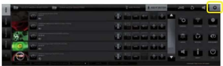
SA (Settings Area Menu) - SYSTEM SETTINGS
Provides UI elements to access control panes for all system settings and functions. Tap/click on a Settings button in SA opens a relevant settings pane in CMA. Some panes have additional PREFERENCES TABS in the top bar of the CMA allowing access to more settings and adjustable parameters.
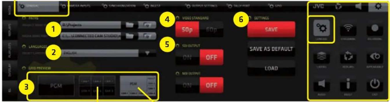
SYSTEM SETTINGS / GENERAL / General Tab contains
- Directories setup, 2. Language choices, 3. Secondary graphics card output layout selector - Grid Preview, 4. Video standard settings, 5. SDI and NDI output settings, 6. Save/Save As Default/Load System Settings - all systems settings are saved/loaded and default settings are created.
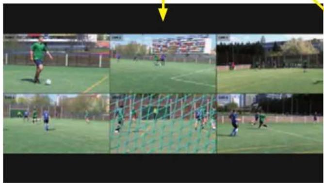
Secondary Graphics Card Output
3 choices are available - Full screen PGM, Camera grid, PGM + Camera monitors + Ingest Input monitor.
6 cam system 2nd Monitor Output Grid example
All cameras preview grid PGM + All cameras + Ingest previews grid
natural_image
Sequence of six photos showing a soccer player in action on a field, with no visible text or symbols.
natural_image
Sequence of outdoor soccer training scenes showing a player kicking a ball, with no visible text or symbols in the main image areas.KM IP5000KM IP5000
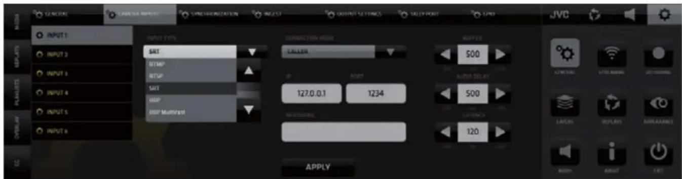
SYSTEM SETTINGS / GENERAL / Camera Input tab
Use the side menu to select an input and choose an input type from the drop-down menu for each. Certain input types require additional setting which are displayed to the right. Setup the necessary settings as needed and push APPLY to make them active.
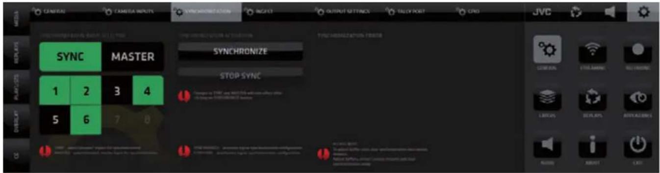
SYSTEM SETTINGS / GENERAL / SYNCHRONIZATION Setting tab
Use it to synchronize remote IP cameras.
- Select cameras to be synchronized by pushing the numbered buttons.
KMJP6000
- Select the camera which will be the MASTER camera to which all the others will synchronize
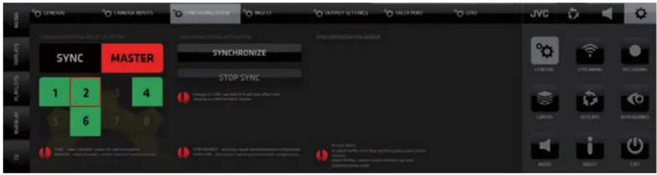
- Push SYNCHRONIZE to start the sync on all selected cameras
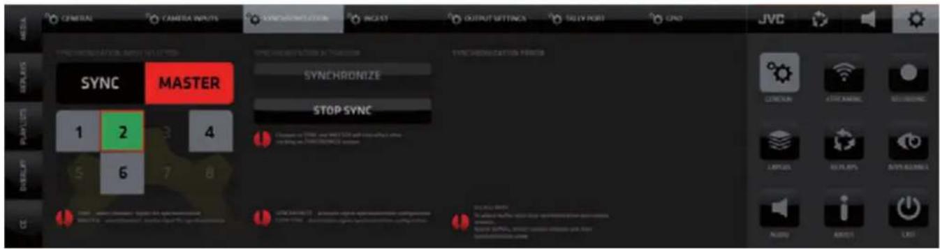
NOTE:
If an input is in a Synchronization group it is not possible to change the input type and settings for this channel in General setting /Camera Inputs Tab. To be able to do it Stop synchronization by pushing STOP SYNC and deselect the camera input from the Synchronization group.
It is recommended to synchronize cameras with identical FPS settings otherwise the synchronization may not function properly.
Only selected JVC camera models are supporting synchronization.
Cameras of other manufacturers are not capable of synchronization.
For correct synchronization of camera streams the in-camera NTP server (Network Time Protocol) must be turned ON and sending correct NTP data to the CCS.
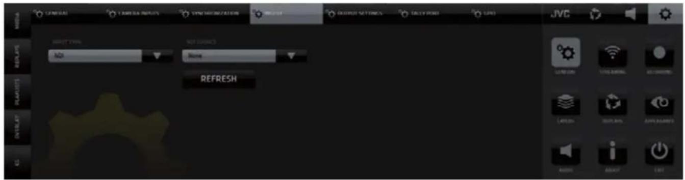
SYSTEM SETTINGS / GENERAL / Ingest Settings
Ingest Layer Input setup - any NDI source, a notebook, action camera, or even a smartphone can be used as sources and inserted into your live production
SYSTEM SETTINGS / GENERAL / Output Settings
- SDI & NDI Output setup
- Return Video feed to JVC camera operators setup

SYSTEM SETTINGS / GENERAL / Tally - 1
Tally & Intercom system selection, communication setup and GPIO device selection for Tally.

SYSTEM SETTINGS / GENERAL / Tally - 2
Selection of a GPIO device used to control on-camera Tally Lights.
Switching cameras will be sending signals to the respective pins to be used by an external GPIO device to control on-camera Tally lights.

SYSTEM SETTINGS / GENERAL / GPIO
Selection of GPIO device to be used with the GPIO buttons in the CCS top menu to control external devices.
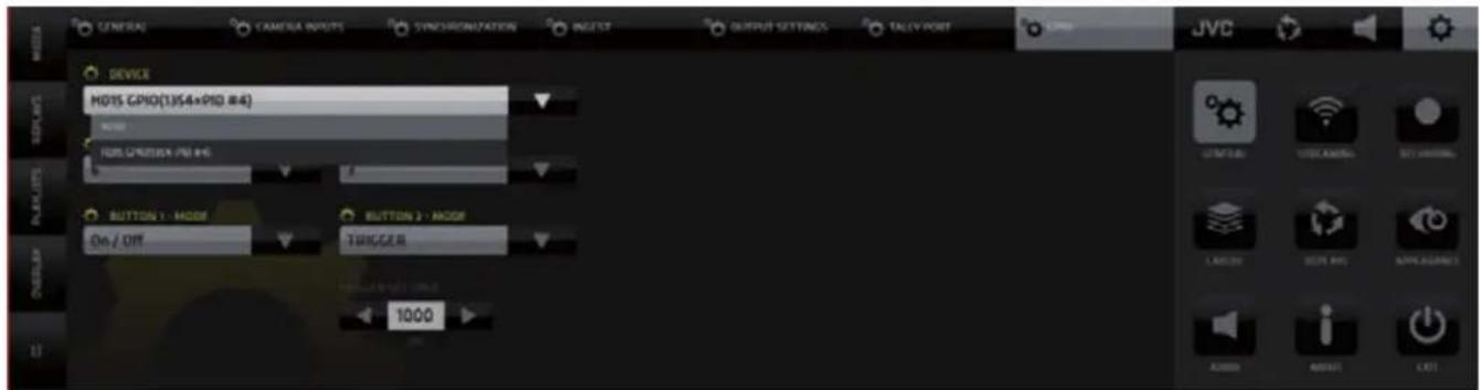
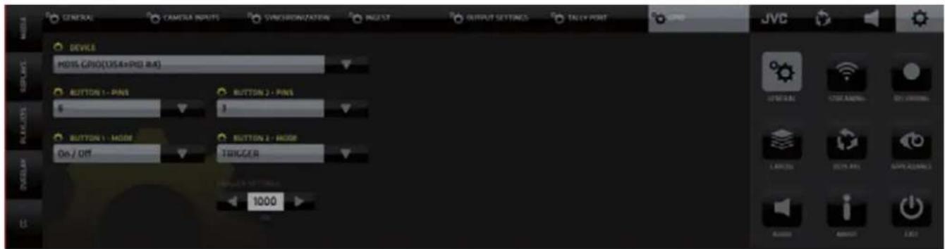
SYSTEM SETTINGS / GENERAL / GPIO - Buttons
Assign PINs to the GPIO buttons and select their operation Mode.
Once the PINs are assigned the GPIO buttons in the GUI become active.
Pressing the GPIO button a signal is be sent to a selected PIN that can be use to control and external device. Two operation modes On/Off or Trigger are available.
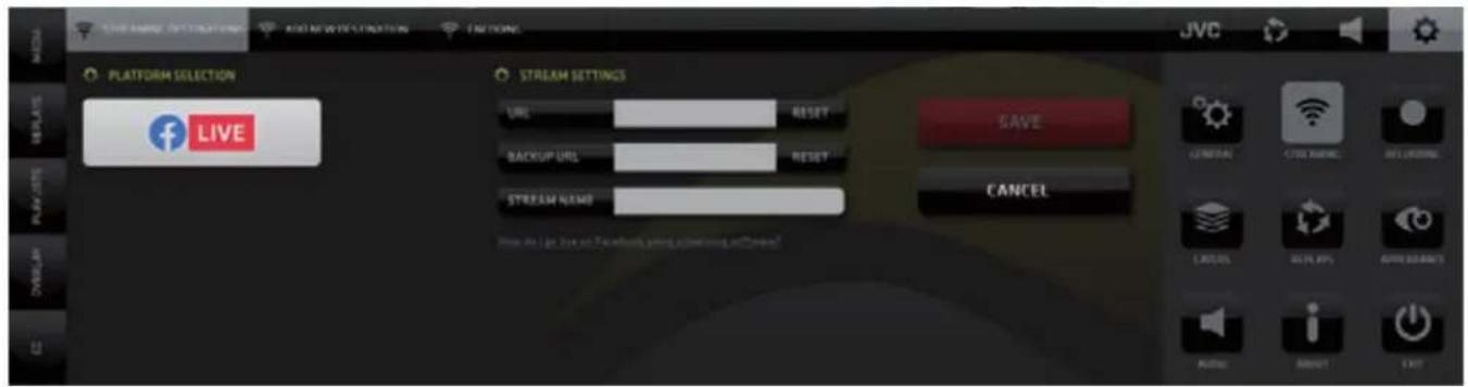
SYSTEM SETTINGS / STREAMING / Streaming Destination tab
Login Data Input for the selected streaming platform - fill in data and SAVE.
The tab content will display the setup destinations in a list view.
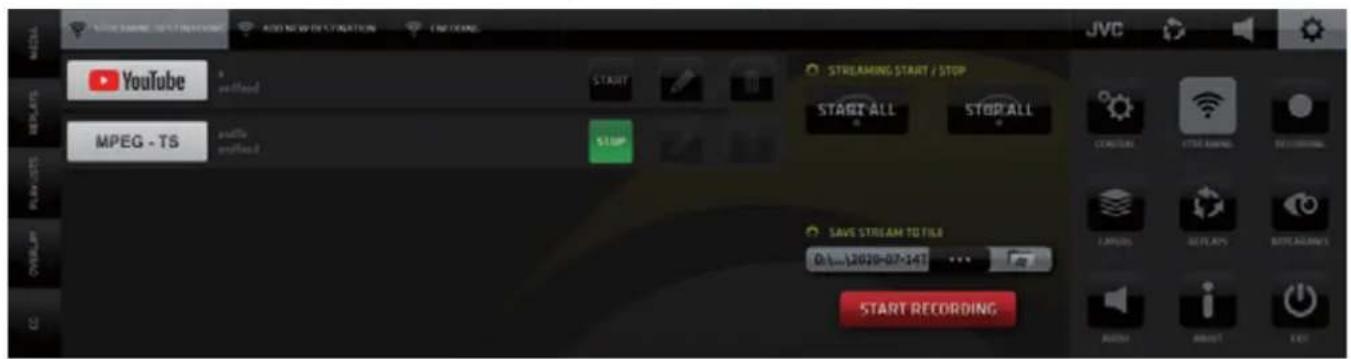
SYSTEM SETTINGS / STREAMING / Streaming Destinations tab - list view
Multiple Streaming Destinations List - streaming controls START, EDIT and DELETE buttons for each streaming destination are provided.
START ALL - start streaming to all destinations
STOP ALL - stop all streaming
SAVE STREAM TO FILE - specify a name and path for the stream file to be saved
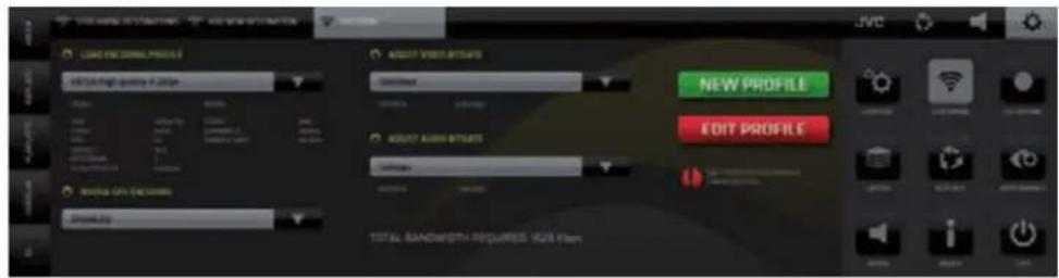
SYSTEM SETTINGS / STREAMING / Add New Destination tab
List of predefined streaming platforms - tap/click any to add to destinations.
The Tab will automatically switch to Streaming destinations - Log in and SAVE.

SYSTEM SETTINGS / STREAMING / Encoding tab
Encoder profile setup - audio/video bit rates
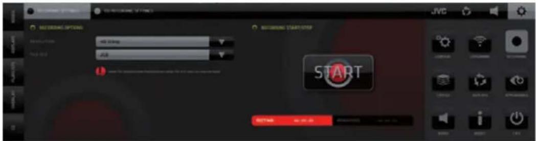
SYSTEM SETTINGS / RECORDING / Recording Settings tab
PGM recording setup - resolution, file size, start/stop, recording / remaining time, and disks info are provided
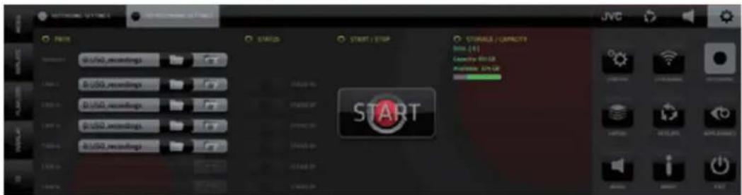
SYSTEM SETTINGS / RECORDING / ISO Recording Settings tab
Camera ISO recording setup, define drives, paths, start/stop recording, storage space info. Please note that ISO recording can only be enabled on cameras that are selected as replay cameras.
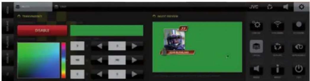
SYSTEM SETTINGS / LAYERS / Ingest tab
A transparency color key can be created on the INGEST input if the input signal is HDMI. ENABLE the Transparency and use the eye drop tool to sample the key color. For best results use video/graphics with a solid color background.
SYSTEM SETTINGS / LAYERS / Logo tab
Use the PATH selector to insert a file .FLV .MOV and PNG files with Alpha channel are supported.
MOV Files Support: ProRes V1, 4444, codec ap4h, colorspace yuva444p12le (BT.709).
It is recommended to use 25-50Mbps bitrate for simultaneous usage of multiple layers at the same time. If only one MOV file is played at once, its bitrate can go up to 100Mbps.
Higher bit rates are not recommended due to performance load.
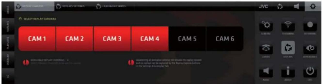
SYSTEM SETTINGS / REPLAYS / Replay Cameras tab
Click buttons to select/deselect cameras for replay use. 4-cam version only shows 4 channels.
KM-IP6000
SYSTEM SETTINGS / REPLAYS / Replay Settings tab
Setup the behavior of replays, replay durations and slow motion playback settings.
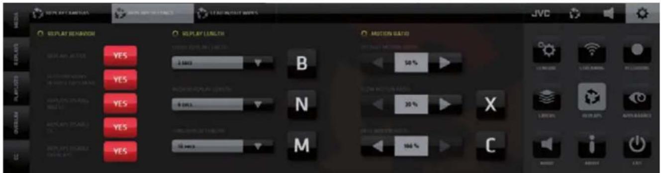
Replay Behavior - activate / deactivate replays in general
- setup automatic replays preview in SRP and DRCS modes
- setup how replays affect the display of graphics
Replay Length - setup the duration of a replay assigned to each replay capture button
Motion Ratio - setup the Slow Motion speed for default, fast and slow replay playback

These settings allow the replay system to be fine tuned specifically for the sport being produced to make it extremely effective and fast. Faster than any other replay system in existence.
SYSTEM SETTINGS / REPLAYS / Lead In/Out Wipes tab
Select replay wipes to be used and the method they are applied to replays. Replay wipes usage statistics are provided as well for monetizing purposes.

SYSTEM SETTINGS / APPEARANCE
SYSTEM SETTINGS / APPEARANCE / PIP tab
PIP border - set color, thickness and shadow on/off

SYSTEM SETTINGS / APPEARANCE / SPLIT tab
SPLIT SCREEN border color and thickness setup
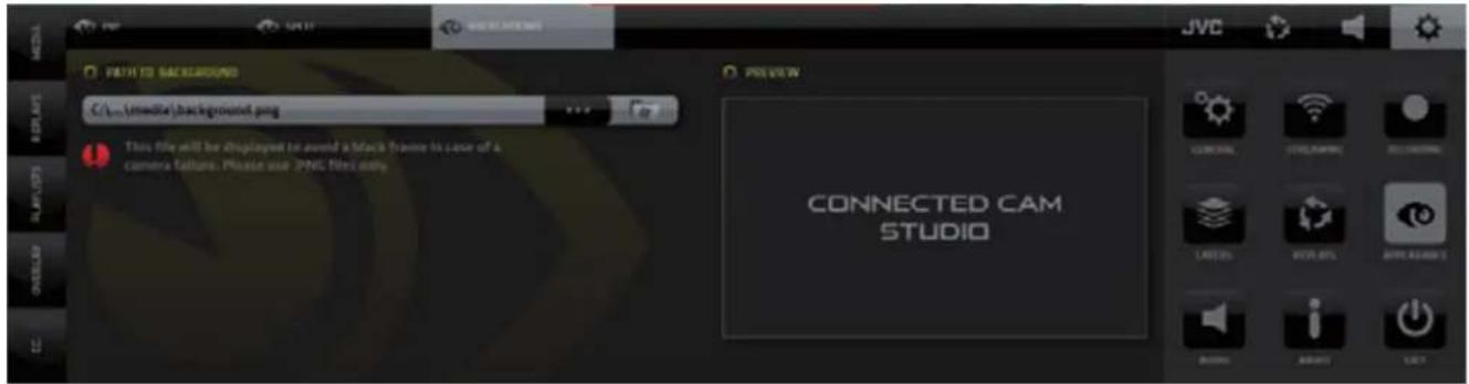
SYSTEM SETTINGS / APPEARANCE / BACKGROUND tab
Setup of a background image to avoid black screen in case of camera dropout.
The image selected will be displayed in the input in case the camera signal is lost.
SYSTEM SETTINGS / AUDIO
Contains two section - on the left is the setup of audio devices, AUX audio delay for A/V synchronization and on the right are the IFB talk-back controls
AUX IN DELAY
Use this to obtain a perfect sync of audio and video

IFB TALK BACK - one way audio communication system between the switcher operator and cameras
- Select a device for IFB audio talk back using the drop-down menu
- SHOW/HIDE buttons reveal an additional ON/OFF button in the SA MENU
- Use this info to set RETURN SERVER setting in the JVC camera
- TALK/MUTE button switches the audio device used for communication ON/OFF
- Fader to adjust the input audio device volume level
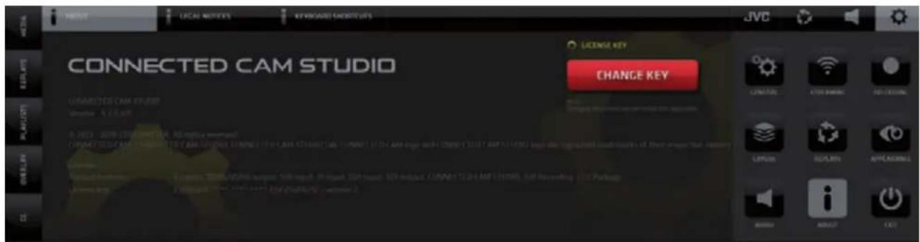
SYSTEM SETTINGS / ABOUT / About tab
Provides system information and license key entry button
CONNECTED CAM STUDIO
SYSTEM SETTINGS / ABOUT / Legal Notices tab
Display of mandatory legal info.
SYSTEM SETTINGS / ABOUT / Keyboard Shortcuts tab
Setup of keyboard shortcuts function.
SYSTEM SETTINGS / EXIT
Tap/click the EXIT button to close the application
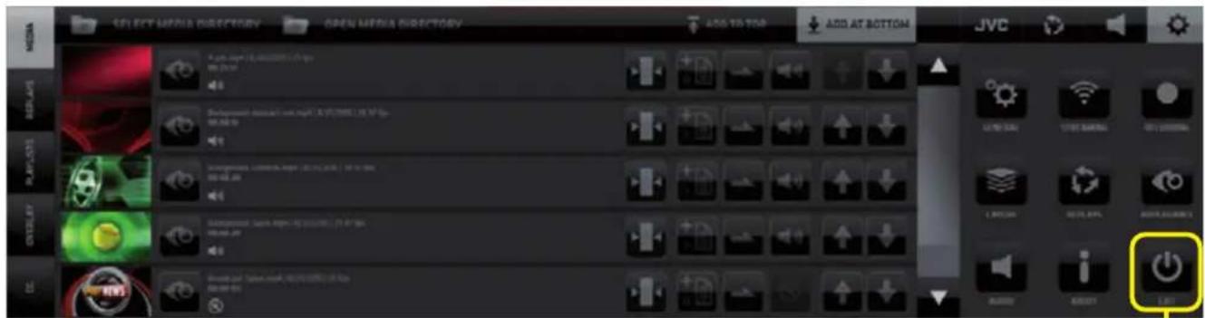
Application shut down / system shut down dialog

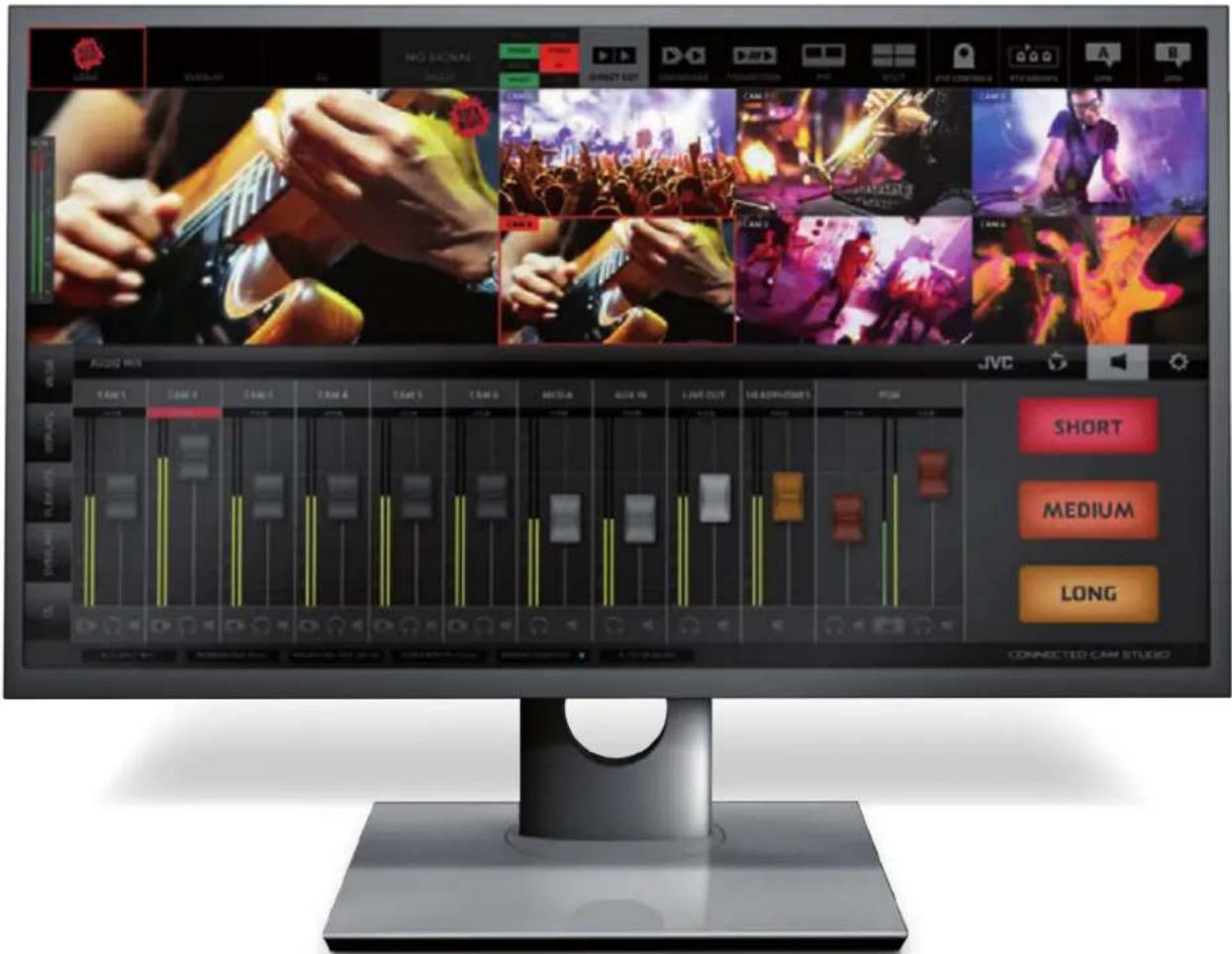
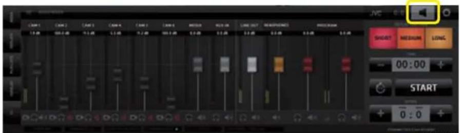
SA (Settings Area Menu) - AUDIO
Activates the display of the AUDIO MIXER in the CMA and the REPLAY CAPTURE buttons in the SA.
The AUDIO MIXER board provides all the standard Audio for Video mixer interface elements.
- Cameras SDI embedded audio faders with level and peak indicators
- Audio Follow Video, Solo and Mute buttons for each fader
- Media audio fader
- AUX input fader (external audio signal source)
- Line Out fader
- Headphones output fader
- Program Output levels stereo faders with levels, peaking and a stereo lock/unlock
Important notes on certain functionalities of the Audio Mixer:
- If the Stereo Lock is Active (locked icon) both PGM faders move in sync relative to each other.
- If the Stereo Lock is Deactivated (unlocked icon) the PGM faders move individually.
- Double clicking on any Fader Button will set its level to the level of 0.0 db
- In the Unlocked state of the PGM Output faders double clicking one PGM Output fader will bring the other PGM fader to the same level as the one that was double-clicked
- In the Locked state of the PGM Output faders double clicking any of the faders will bring both their levels to the level of 0.0 db

KM-IP4100
NOTE: 1. All faders have integrated Level and Peaking indicators
- Basic knowledge of audio mixer operation is required. It is beyond the scope of this manual to explain Audio Mixer board operational procedures.

AUDIO FOLLOW VIDEO
The functionality makes the audio mixer a slave to the video mixer.
When the functionality is active (red icon at bottom left of the input fader) switching to another camera will also switch the audio to that channel. If the AFV button is OFF (grey) the audio of the input is mixed to the Program audio regardless of switching cameras.
Example of a practical would be to have one camera AFV Off to capture the ambiance audio that always goes out to PGM and the rest of the cameras have AFV On so the audio of those cameras is switched with switching cameras.
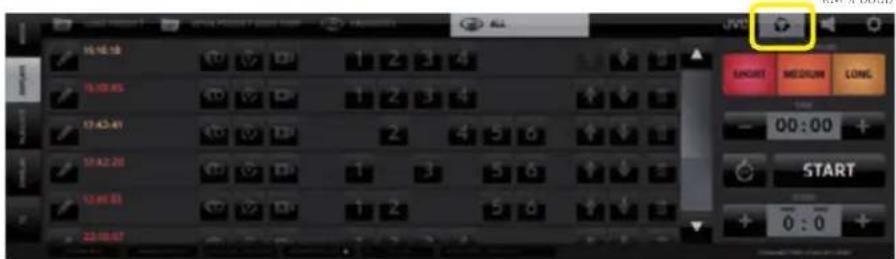
SA (Settings Area Menu) - REPLAYS
CONNECTED CAM STUDIO
Activates the display of the REPLAY CAPTURE BUTTONS in the SA(Settings Area)
and the REPLAYS LIST in the CMA (Content Management Area)
Activating another functionality in the left side menu will change the content of the CMA but as long as the SA REPLAY SWITCH IS ON the replay capture buttons will remain available.
NOTE:
The Replay functionality was described in great detail on pages 20-25. and the Replay Settings on page 47. Please refer to these pages to review the Replay functionality.
KM-IP4100
SA (Settings Area) - JVC CAMERA CONTROL
It provides all the interface elements to remotely control JVC camcorders or PTZ cameras - over IP. It is divided into 6 TABS with various logically related controls.
- IP CONNECT - contains all parameters to establish a connection to a camera
- STREAM SETTINGS - contains all parameters to setup camera stream
- CONTROL - contains all camera settings available to be controlled over IP
- ZOOM & FOCUS - contains zoom focus, presets, recording start/stop controls
- PTZ - contains all controls to operate individual JVC PTZ cameras and to create camera presets
- PTZ GROUPS - contains tool for creation of PTZ camera groups and group presets
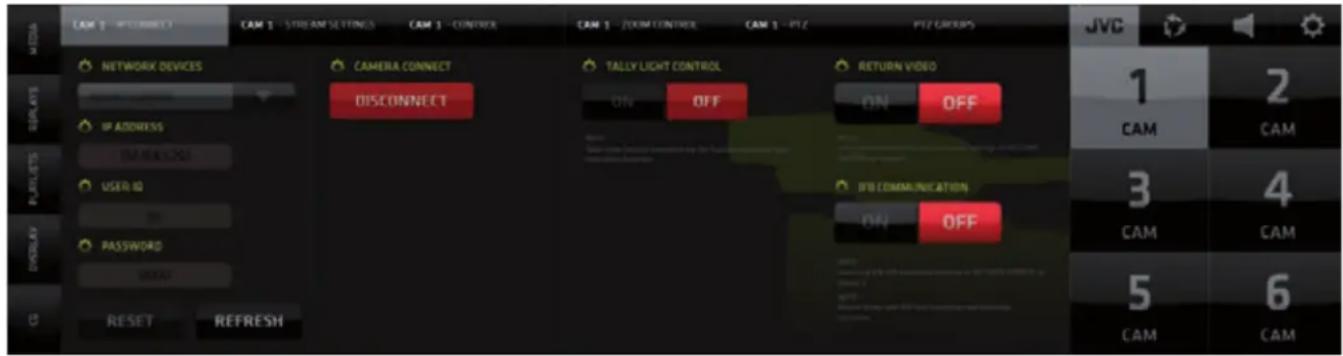
IP CONNECT Tab
- Setup of the camera IP connection
- select a camera available on the network
- fill out credentials
- RESET button clears all filled info
- REFRESH button updates the available network devices
• TALLY LIGHT CONTROL - if ON the CCS takes over the on-camera recording light and uses it as TALLY LIGHT
- RETURN VIDEO - if ON the CCS sends PGM video/audio to the camera (refer to page 43).
- IFB COMMUNICATION - if ON the CCS sends IFB audio to the camera (refer to page 48).
STREAM SETTINGS Tab
Provides access to all settings to control the streaming parameters/settings of the JVC Camera selected.
• Active Stream Server Info - provides text readout of camera active streaming server settings
- Start Stream/Stop Stream - start/stop active camera stream server
- Select Server / Rename - select one of 4 available servers and rename it if desired
- Server Type - select type of server
- Load Server - read current camera streaming server setting
- Server Setup - each type of server requires specific setting to be setup
- Resolution/FPS/Bitrate - camera stream properties
- Apply Changes - applies the changes made to the camera server
- Set As Input - sets the streaming camera as an input in the selected CCS camera channel

NOTE: For details on the functionality of JVC cameras please refer to the camera users manual.
CONTROL Tab
Provides access to all settings of the JVC camera that can be controlled over IP. Available controls will differ depending on what camera type is connected to the CONNECTED CAM STUDIO.
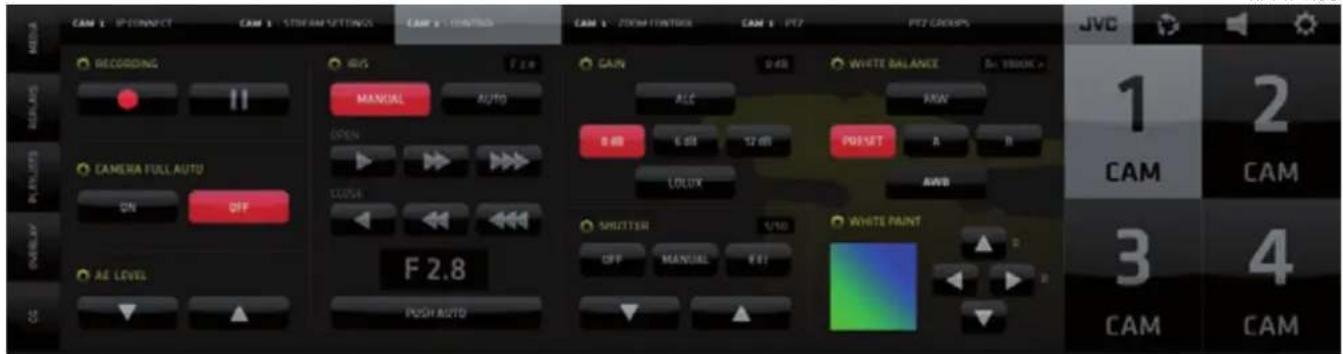
NOTE: For details on the functionality of JVC cameras please refer to your camera users manual.
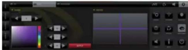
ZOOM CONTROL Tab
Provides access to the ZOOM and FOCUS related JVC camera controls.
If a PTZ camera is connected a PAN/TILT control grid will displayed as well.
KM-IP4100

PTZ PRESETS Tab
JVC PTZ camera PRESET controls:
• Pan/Tilt with movement speed adjustment slider
• Speed Relative to Zoom On/Off
- Presets - 14 memory slots to store the PTZ camera position
KM-IP4100
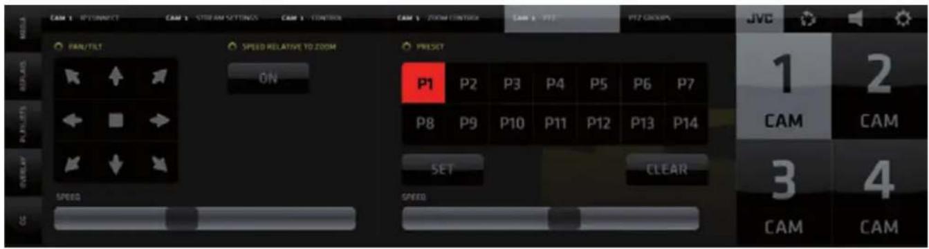
PTZ controls operating procedures:
- Pan/Tilt - press and hold the directional arrow buttons to move the camera to a desired position
• Speed Relative to Zoom - The wider the zoom the faster the speed of movement and vice-versa - Presets - to create and store a camera preset tap/click the SET button followed by the PRESET
(P1 - P14) button - the current settings for this camera is stored as a preset
- to activate a stored camera preset just push a Preset button (P1 - P14)
- to clear a preset push CLEAR button followed by the Preset button (P1 - P14)
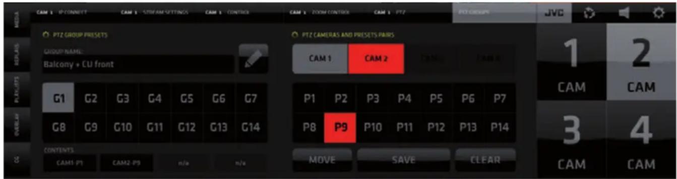
PTZ GROUPS PRESETS Tab
Provide access to the JVC - PTZ camera groups controls:
- Combine individual camera presets into 14 groups of GROUP PRESETS
- Execute a Group Presets - instantly move multiple cameras to positions assigned in the group preset
KM-IP4100
Creating a PTZ Group:
- Select a slot (button) for a new group preset in the grid of buttons on the left G1 - G14
- Select a camera in the upper row of buttons of the PTZ CAMERAS AND PRESETS PAIRS on the right
-
Choose a preset for the selected camera P1 - P14 that will be used when this Group preset is activated Note: Steps 2 & 3 created a so called “Camera+Preset PAIR”
-
Repeat steps 2 & 3 and create more Camera+Preset pairs
- add as many as you wish - up to 4 are possible
- Name the preset - Select a Group Preset and Click the PENCIL button above the G1-G7 buttons.
Type a name/note in the field - tap Pencil when done
-
Tap/click SAVE to save the group preset
-
To CLEAR the contents of a Group Preset tap/click CLEAR and tap whatever you wish to clear it can be a Camera+Preset pair in the group or the entire group.
When done deactivate the clear function by tap/click on the CLEAR button again to turn it off
- Tap/click MOVE to execute the Group Preset.
Executing a Group Preset will move all cameras in the group to their chosen presets at once.
If a camera is in LIVE PGM it will not move. Only after it is switched off it will move to complete the Group Preset.
In the example below a GROUPS PRESET - G14 was created.
It contains 2 Camera+Preset Pairs: CAM1-P3 and CAM2-P10. The content of the selected group preset is indicated in the CONTENTS fields below the Group Preset buttons (outlined 9). The Camera+Preset pairs are clearly listed.

KM-IP4100
TOP MENU - Camera Presets and Group Presets - GUI explained
Now that we understand how the Camera presets and Camera groups work we can return to the two PTZ functionality buttons in the TOP MENU.
As mentioned earlier these 2 buttons will become active automatically if PTZ CAMERAS are connected to the system.

PTZ CONTROLS
- Tap/click on the PTZ CONTROLS button (1) to reveal the PTZ CAMERA CONTROLS for each PTZ camera detected by the CONNECTED CAM STUDIO SW
- Two buttons with icons become visible in the live monitors of the PTZ cameras,
2A - Camera PRESETS
2B - Camera settings HOT KEY
3. Tap/click on the Preset button (2A) reveals a PRESETS GRID of all available presets for this PTZ camera
a - These presets are created in the PTZ CAMERA PRESETS pane in the JVC PTZ Tab.
b - tap/click any of the PRESET (P1-P14) buttons and the camera moves to that position immediately
c - tap/click the [X] button in lower right to close/hide the PRESETS GRID.
KM-IP4100


While the Camera Presets Grid is revealed in the camera monitor, switching of that camera is temporarily unavailable. Click the [X] button to close the grid to go back to switching capability.
- Tap/click on the CAMERA SETTINGS HOT KEY button (2B) opens the PTZ camera settings in the CMA so quick changes to PTZ Camera presets can be made when needed.
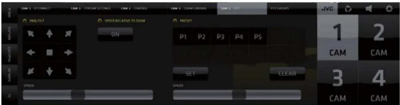
KM-IP4100
PTZ GROUPS
The last button in the top menu reveals PTZ GROUP controls
- Tap/click on the PTZ GROUP button reveals the PTZ GROUP CONTROLS
- In the PGM monitor area, 2 buttons become visible
2c - PTZ Camera GROUP PRESETS
2d - PTZ Camera GROUP PRESETS HOT KEY
- Tap/click the Preset button (2c) reveals the GROUP PRESETS GRID and it's controls
a - Numbered presets created in the PTZ CAMERA GROUP PRESETS pane (G1 - G14) in the JVC PTZ CAMERA GROUPS PRESETS Tab.
b - tap/click to select any of the PRESET (G1 - G14)
c - tap/click the MOVE button to move all cameras to their respective presets
d - tap/click the [X] button in lower right to close/hide the PTZ GROUP PRESETS GRID
e - information display about the content of the Group Preset - name, comment and camera/preset pairs contained in it.
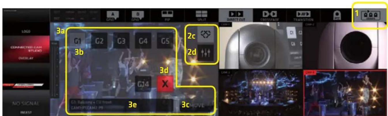
KM IP4100
- Tap/click on the CAMERA SETTINGS HOT KEY button (2d) opens the PTZ CAMERA GROUPS settings in the CMA so quick changes to PTZ Camera Group Presets can be made when needed.

KM-IP4100
NOTE:
If you no longer wish to work with individual camera presets or camera group presets switch of the PTZ presets and PTZ group presets buttons to have a clean view of the live camera monitors.
For more information on CONNECTED CAM STUDIO please visit: https://www.jvc.net/
For support please contact:
USA: http://pro.jvc.com/prof/support/index.jsp
EMEA: Please contact the local dealers in your area
JAPAN: info_sjs@jvckenwood.com
Thank You for using CONNECTED CAM STUDIO.
Enjoy!
- CONNECTED CAM STUDIO
- MULTI-CAMERA LIVE PRODUCTION AND STREAMING STUDIOS
- Table of Contents
- Copyright notice.
- WELCOME
- CONNECTED CAM STUDIO - Live Production Software
- END USER LICENSE AGREEMENT
- GUI - Graphical User Interface Overview
- NOTE:
- SOFTWARE START
- CREATING A PROJECT
- LOAD PROJECT dialog screen:
- PRODUCTION LAYOUT Section
- LAYERS:
- ACTIVITY INDICATORS:
- OUTPUT indicators color codes:
- RECORDING indicators color codes:
- SCREEN LAYOUT SWITCHES
- Operating procedure:
- SPLIT SCREEN - enables the split screen layout functionality
- Adjusting the Mixing Modes parameters:
- Crossfade Duration Adjustment:
- Transition Template Selection and Duration Adjustment:
- PTZ CAMERA CONTROL
- GPIO A and B buttons
- GPIO PINs assignment when used to control Tally
- GPIO PINs assignment conflict warning
- PGM / CAMERA SWITCHING SECTION
- PGM Monitor
- JVC PTZ CAMERA PRESETS and PTZ CAMERA GROUP PRESETS controls display
- Live Camera Monitors
- c, Autocut switches display
- d, PTZ CAMERA PRESETS control switches
- CMA (Content Management Area) - MEDIA Tab
- The MEDIA pane top bar contains 4 TABS:
- Media List Item
- MEDIA IN/OUT POINTS EDITOR
- IN/OUT POINTS control elements functionality description
- 1st row - PREVIEW/EXIT/ DURATION/ RESET (left to right)
- 2nd row - IN/OUT POINTS SET/NAVIGATE (left to right)
- 3rd row - TIMELINE BAR
- 4th row - VIDEO NAVIGATION CONTROLS (left to right)
- MEDIA IN/OUT POINTS SETUP PROCEDURE
- AUTOCUT
- Procedure to operate:
- CMA (Content Management Area) - REPLAYS Tab
- The REPLAY pane top bar contains 4 TABS:
- Each REPLAY SET contains the following controls buttons:
- REPLAY CAPTURE
- REPLAY CAPTURE BUTTONS
- SHORT
- MEDIUM
- LONG
- Replay Capture and Playback procedure
- REPLAY MODES
- CLOSING REPLAY PREVIEW
- DRCS - DYNAMIC REPLAY CAMERA SWITCHING mode
- FAVORITES and REPLAY HIGHLIGHTS
- SLOW MOTION REPLAY PLAYBACK / FREEZE FRAME
- DELETING REPLAYS
- AUTOCUT IN REPLAYS
- WIPES
- CMA (Content Management Area) - PLAYLISTS Tab
- Playlist Management
- CMA (Content Management Area) - OVERLAYS Menu Tab
- OVERLAYS Operation Procedure:
- CMA (Content Management Area) - CG Menu Tab
- Adding a CG to a CG Project / Creating / Managing CG Projects
- CG Operation Procedure:
- NOTE: The CG Object TYPE is indicated by the CG Type ICON under the CG Name.
- CG OBJECT CONSTRUCTION
- CG PARAMETERS EDITING
- - BACKGROUND Layer
- • TEXT and CRAWL Layer
- • DYNAMIC TEXT Layer
- BACKGROUND Layer parameters setup
- Buttons at bottom:
- TEXT Layer parameters setup
- CRAWL Text Layer parameters setup
- CRAWL DIRECTION and LOOP parameters setup
- TEXT LAYER COLOR parameters setup
- CG SEQUENCE
- CG Sequences
- CG Sequences Tab
- TIMER/SCORE CG Objects
- TIMER/SCORE CG Object - Layers Setup
- CLOCK Parameters Setup
- GAME PARTS Parameters Setup
- SCORE Parameters Setup
- TIME/SCORE CONTROLLER functionality
- AUTOMATIC DATA CONTROL
- Procedure:
- EDITING AND XML PRESET
- SA - SETTINGS AREA MENU Tabs
- The SA Menu Tabs change the content of both the SA and CMA as follows:
- SYSTEM SETTINGS Tab
- AUDIO MIXER Tab
- REPLAYS Tab
- JVC CAMERA CONTROLS Tab
- SA (Settings Area Menu) - SYSTEM SETTINGS
- SYSTEM SETTINGS / GENERAL / General Tab contains
- Secondary Graphics Card Output
- cam system 2nd Monitor Output Grid example
- SYSTEM SETTINGS / GENERAL / Camera Input tab
- SYSTEM SETTINGS / GENERAL / SYNCHRONIZATION Setting tab
- SYSTEM SETTINGS / GENERAL / Ingest Settings
- SYSTEM SETTINGS / GENERAL / Output Settings
- SYSTEM SETTINGS / GENERAL / Tally - 1
- SYSTEM SETTINGS / GENERAL / Tally - 2
- SYSTEM SETTINGS / GENERAL / GPIO
- SYSTEM SETTINGS / GENERAL / GPIO - Buttons
- SYSTEM SETTINGS / STREAMING / Streaming Destination tab
- SYSTEM SETTINGS / STREAMING / Streaming Destinations tab - list view
- SYSTEM SETTINGS / STREAMING / Add New Destination tab
- SYSTEM SETTINGS / STREAMING / Encoding tab
- SYSTEM SETTINGS / RECORDING / Recording Settings tab
- SYSTEM SETTINGS / RECORDING / ISO Recording Settings tab
- SYSTEM SETTINGS / LAYERS / Ingest tab
- SYSTEM SETTINGS / LAYERS / Logo tab
- SYSTEM SETTINGS / REPLAYS / Replay Cameras tab
- SYSTEM SETTINGS / REPLAYS / Replay Settings tab
- SYSTEM SETTINGS / REPLAYS / Lead In/Out Wipes tab
- SYSTEM SETTINGS / APPEARANCE
- SYSTEM SETTINGS / APPEARANCE / PIP tab
- SYSTEM SETTINGS / APPEARANCE / SPLIT tab
- SYSTEM SETTINGS / APPEARANCE / BACKGROUND tab
- SYSTEM SETTINGS / AUDIO
- AUX IN DELAY
- IFB TALK BACK - one way audio communication system between the switcher operator and cameras
- SYSTEM SETTINGS / ABOUT / About tab
- SYSTEM SETTINGS / ABOUT / Legal Notices tab
- SYSTEM SETTINGS / ABOUT / Keyboard Shortcuts tab
- SYSTEM SETTINGS / EXIT
- SA (Settings Area Menu) - AUDIO
- Important notes on certain functionalities of the Audio Mixer:
- NOTE: 1. All faders have integrated Level and Peaking indicators
- AUDIO FOLLOW VIDEO
- SA (Settings Area Menu) - REPLAYS
- SA (Settings Area) - JVC CAMERA CONTROL
- IP CONNECT Tab
- STREAM SETTINGS Tab
- CONTROL Tab
- ZOOM CONTROL Tab
- PTZ PRESETS Tab
- PTZ controls operating procedures:
- PTZ GROUPS PRESETS Tab
- Creating a PTZ Group:
- TOP MENU - Camera Presets and Group Presets - GUI explained
- PTZ CONTROLS
- PTZ GROUPS
Brand : JVC
Model : KM-IP4100
Category : Video Production Software