RLFDX485S2/24DC - Wi-Fi Router ComNet - Free user manual and instructions
Find the device manual for free RLFDX485S2/24DC ComNet in PDF.


| Product Type | Substation-rated RS-422 & RS-485 Serial Data Link/Repeater |
| Model | RLFDX485S2/24DC |
| Fiber Type | Single-mode (9-13 μm core) |
| Optical Connector | ST |
| Wavelength | 1300 nm |
| Optical Budget (Typical) | 19 dB |
| Data Rate | DC to 2 Mbps |
| Data Format | EIA RS-422 or RS-485 |
| Transmission Distance | Up to ~30 km (9/125 cable @0.3 dB/km) |
| Power Input | 9 to 36 VDC, 250 mA (via D-connector pin 9 or external power connector) |
| Power Consumption | 3.0 Watts (10.2 BTU/h) |
| Operating Temperature | -40°C to +70°C |
| Storage Temperature | -40°C to +85°C |
| Dimensions (W x L x H) | 2.0 x 5.1 x 1.3 inches (51 x 130 x 33 mm) |
| Weight | 9 oz (255 g) |
| Data Connector | 9-pin D-Type Female |
| Configuration Switches | HD/FD, AC/DC Coupling, Link/Repeat, Hold-Over (×2), Invert/Norm, Test Mode, Bias (×2) |
| Diagnostic LEDs | Power, Transmit Fiber (TO), Transmit Electrical (TE), Receive Fiber (RO), Receive Electrical (RE) |
| Compliance | FCC Part 15 Class A, CE |
Frequently Asked Questions - RLFDX485S2/24DC ComNet
User questions about RLFDX485S2/24DC ComNet
0 question about this device. Answer the ones you know or ask your own.
Ask a new question about this device
Download the instructions for your Wi-Fi Router in PDF format for free! Find your manual RLFDX485S2/24DC - ComNet and take your electronic device back in hand. On this page are published all the documents necessary for the use of your device. RLFDX485S2/24DC by ComNet.
USER MANUAL RLFDX485S2/24DC ComNet
natural_image
Two blue COMNET devices with ports and connectors, no visible text or symbols on the main body.INSTALLATION AND OPERATION MANUAL
RELIANCE
RLFDX485 Series
SUBSTATION-RATED RS-422 & RS-485 DATA LINK/REPEATER FOR REPLACEMENT OF GARRETTCOM/DYMEC 5845 & 5846 SERIES
This manual serves the following ComNet Model Numbers:
RLFDX485M2/24DC
RLFDX485M2/HV
RLFDX485M2/48DC
RLFDX485S2/24DC
RLFDX485S2/HV
RLFDX485S2/48DC
The ComNet™ RLFDX series of serial data link/repeaters are substation-rated and industrially hardened form, fit, function and completely backwards-compatible replacements for the popular Garrettcom/Dymec 5845 & 5846 series of RS-422 and RS-485 serial data link/repeaters. They are designed for deployment in environments where high levels of electromagnetic noise and interference (EMI) and severe voltage transients and surges are routinely encountered, such as electrical utility substations and switchyards, heavy manufacturing facilities, trackside and roadside electronic equipment, and other difficult out-of-plant applications. Optical connectivity provides significantly extended transmission distances compared to copper media; high levels of electrical isolation; enhanced reliability and protection for peripheral IEDs, RTUs, and other equipment; and operational safety.
The RLFDX series of serial data link/repeaters are easily field-configurable for point-to-point, point-to-multipoint/Local-Remote, loop, or bus topologies. They may be also used for electrical data protocol translation: an RLFDX232-series RS-232 modem and IED/RTU can communicate directly with an RLFDX485-series RS-422/RS-485 modem and IED/RTU.
The extremely versatile and simple-to-install RLFDX series is ideal for any mission-critical application where very high levels of reliability and network availability are of the utmost importance.
Contents
FCC/CE Regulation 4
Warranty 4
Disclaimer 4
Safety Information 4
ComNet / Garretcom Interoperability / Compatibility Listing 5
Warnings, Cautions, and Notes Used in this Publication 6
1. Introduction 7
1.1 Definitions 8
1.2 RLFDX485(M,S)2/24DC Link/Repeaters 11
1.2.1 9 Pin Data Port D-connector 13
1.2.2 Switch Settings 13
1.2.3 HD / FD Switch 14
1.2.4 Repeat Switch 14
1.2.5 Logic Inversion Switch 14
1.2.6 Input Bias Switch 14
1.2.7 Input Data Coupling Switch 15
1.2.8 Enable Holdover Switch 15
1.2.9 Test Mode Option Switch 16
1.2.10 Optical Ports 16
1.2.11 Diagnostic LEDs 17
1.2.12 Power Connections 17
1.2.12.1 Powering Models RLFDX485(M,S)2/24DC 17
1.2.12.2 Powering Models RLFDX485(M,S)2/48DC 18
1.2.12.3 Powering Models RLFDX485(M,S)2/HV 18
1.2.13 Peripheral Equipment 19
1.2.13.1 IED 19
1.2.13.2 Fiber Optic Cable (FOC) 19
2. Configurations, Operation, and Installation 20
2.1 Point-To-Point Configuration 21
2.1.1 Installation 22
2.2 LOOP OPERATION - Local/Remote CONFIGURATION 25
2.2.1 Installation 27
2.3 Loop Operation - Peer-To-Peer Configuration 28
2.3.1 Installation 30
3. Applications 31
3.1 Data Rate 31
3.2 Optical Budget 31
3.2.1 Cable Attenuation Factors 32
3.2.1.1 Diameter 32
3.2.1.2 Fittings 32
3.2.1.3 Aging 32
3.2.2 Extending the Distance 33
3.3 Number Of Repeats 33
3.3.1 Effects of Data Rate 34
3.3.2 Pulse Width Distortion 34
3.3.3 Temperature Effect 34
3.4 Types Of Communication 35
3.5 Logic Inversion Switch 35
3.6 Echo Control For 2-Wire RS-485 Local Units In Loop Configurations 36
3.7 Types Of Communication 36
3.9 Selection of Fiber Optic Cables (FOC) 37
4. Testing And Troubleshooting 38
4.1 Testing 38
4.2 Troubleshooting 39
5. Specifications 40
5.1 Electrical and Optical Specifications 40
5.2 Outline Configuration & Mechanical Dimensions for Models RLFDX485(M,S) 43
5.3 Outline Configuration & Mechanical Dimensions for Models RLFDX485(M,S)2/(48DC,HV) 44
FCC/CE Regulation
NOTE: This equipment has been tested and found to comply with the limits for a Class A digital device, pursuant to Part 15 of the FCC Rules. These limits are designed to provide reasonable protection against harmful interference when the equipment is operated in a commercial environment. This equipment generates, uses, and can radiate radio frequency energy and, if not installed and used in accordance with the instruction manual, may cause harmful interference to radio communications. Operation of this equipment in a residential area is likely to cause harmful interference in which case the users will be required to correct the interference at their own expense.
Warranty
ComNet warrants that all ComNet products are free from defects in material and workmanship for a specified warranty period from the invoice date for the life of the installation. ComNet will repair or replace products found by ComNet to be defective within this warranty period, with shipment expenses apportioned by ComNet and the distributor. This warranty does not cover product modifications or repairs done by persons other than ComNet-approved personnel, and this warranty does not apply to ComNet products that are misused, abused, improperly installed, or damaged by accidents.
Please refer to the product's data sheet for the actual warranty period(s) of the product(s) associated with this publication. Data sheets can be found at http://www.comnet.net/comnet-products/
Disclaimer
Information in this publication is intended to be accurate. ComNet shall not be responsible for its use or infringements on third-parties as a result of its use. There may occasionally be unintentional errors on this publication. ComNet reserves the right to revise the contents of this publication without notice.
Safety Information
» Only ComNet service personnel can service the equipment. Please contact ComNet Technical Support.
» Do not attempt to disassemble the link/repeaters as there are no serviceable parts within. This action will void the warranty.
» The equipment should be installed in locations with controlled access, or other means of security, and controlled by persons of authority.
ComNet / Garretcom Interoperability / Compatibility Listing
| Model Data Format Fiber Type Input Power | Equivalent Dymec Model | |||
| RLFDX485M2/24DC | RS-422/RS-485 | Multimode | 9 to 36 VDC | 5845HRT |
| RLFDX485M2/HV | RS-422/RS-485 | Multimode | 88 to 300 VDC / 85 to 264 VAC | 5846HRT-H |
| RLFDX485M2/48DC | RS-422/RS-485 | Multimode | 36 to 59 VDC | 5846HRT-L |
| RLFDX485S2/24DC | RS-422/RS-485 | Single Mode | 9 to 36 VDC | 5845SHRT |
| RLFDX485S2/HV | RS-422/RS-485 | Single Mode | 88 to 300 VDC / 85 to 264 VAC | 5846SHRT-H |
| RLFDX485S2/48DC | RS-422/RS-485 | Single Mode | 36 to 59 VDC | 5846SHRT-L |
Warnings, Cautions, and Notes Used in this Publication
WARNING
Warning notices are used in this publication to emphasize that hazardous voltages, currents, or other conditions that could cause personal injury exist in this equipment or may be associated with its use.
In situations where inattention could cause either injury or damage to equipment, a Warning notice is used.
CAUTION
Caution notices are used where equipment malfunction is possible if care is not taken.
NOTE / APPLICATION NOTE
Notes and Application Notes call attention to information that is especially significant to understanding and operating the equipment.
This document is based on information available at the time of its publication. While efforts have been made to be accurate, the information contained herein does not purport to cover all details or variations, or to provide for every possible contingency in connection with installation, operation, or maintenance.
ComNet assumes no obligation of notice to holders of this document with respect to changes subsequently made.
ComNet makes no representation or warranty, expressed, implied, or statutory with respect to, and assumes no responsibility for the accuracy, completeness, sufficiency, or usefulness of the information contained herein. No warranties of merchantability or fitness for purpose shall apply.
Permission is granted to make a reasonable number of copies of this document for the use within the organization that has purchased the equipment.
"Link/Repeater" is used exclusively to describe this family of Fiber Optic Data Links.
1. Introduction
ComNet Models RLFDX485M2/24DC, RLFDX485S2/24DC, RLFDX485M2/48DC, RLFDX485S2/48DC, RLFDX485M2/HV and RLFDX485S2/HV are data communications Link/Repeaters, which allow the replacement of copper wire media with fiber optic cable. Link/Repeaters simply convert electrical signals to light for transmission, and when received, convert the light signals back to an electrical format. This is done for RS-422 or RS-485 protocols.
These Link/Repeaters are passive to software protocols. They are not addressable in communication protocols, and do not provide any control logic capability to support communication protocols. Link/Repeaters are designed with several features that allow for easy installation and flexibility in configuring for various communication systems.
The multimode RLFDX485M2/XX and singlemode RLFDX485S2/XX series are functionally identical, with the exception of the operating voltage requirements.
NOTE
This manual makes reference to the multimode Model RLFDX485M2/24DC, RLFDX485M2/48DC, and Model RLFDX485M2/HV when describing features and functionality of the Link/Repeaters. These descriptions generally apply to the singlemode Model RLFDX485S2/24DC, RLFDX485S2/48DC, and Model RLFDX485S2/HV as well. When different, a specific reference is made identifying the particular model(s) and their variation(s). The User should read this manual to fully understand how to use the many features of the Link/Repeaters in an effective communication system.
1.1 Definitions
The following terms are used in this manual:
| IED An IED is any intelligent electrical device capable of RS-422 or RS-485 data communications, such as; a computer, RTU, PLC, “smart” meter, relay, etc. The IED must have resident software or firmware that manages the data communication logic, including protocol (formatting and timing), addressing capability (if required), control logic software “handshaking”, and scheduling. | |
| Point-to-Point Configuration | Two Link/Repeaters directly connected to each other. |
| Local/Remote Loop Configuration | More than two Link/Repeaters connected together where the fiber optic cable connects the T optical port of one device to the R optical port of the next unit in the loop. One IED is designated as the Local and controls all the communication and the other IEDs act as Remotes and respond only when specifically polled by the Local. |
| Peer-to-Peer Loop Configuration | More than two Link/Repeaters connected together where the fiber optic cable connects the T optical port of one device to the R optical port of the next unit in the loop. Each IED has the capability of becoming loop Local as allowed by the controlling software. |
| Echo The return of the Local’s transmission back to the Local after traveling around the optical loop. | |
| Optical Bus Configuration | More than two Link/Repeaters connected together in a manner where the Local’s transmission is heard by all IEDs and there is no returning echo of this transmission. |
| Local The Local is the IED that controls the loop in a Local/Remote loop. This IED is responsible for the control of the loop, the polling of the Remotes for information, and the prevention of data collisions. All loop communication is echoed back to and stops at the Local. The Local’s Repeat Switch is always in the “OFF” position. | |
| Remote A Remote is an IED that is passive in a Local/Remote loop. A Remote’s communication is under the control of the Local, and should be controlled to prevent data collision in the loop. All communication generated by the Local will be repeated through each Remote and back to the Local. A Remote’s Repeat Switch is always in the “ON” position. | |
| Peer Peers are IEDs that have equal status and each may Local the loop when allowed by the software. A Peer’s Repeat Switch is always in the “OFF” position and a Peer IED controls pin 8 of its Link/Repeater in order to obtain status as loop Local. | |
| FOC Fiber Optic Cable. | |
| Single-mode Single-mode fibers generally have diameters of 5μm to 13μm. Because of this small core, only one axial path for light propagation is available through the fiber. The optics required to drive single-mode fiber have to be highly focused so that minimum dispersion occurs. Although more costly optical emitters are required, the major benefit is that longer transmission distances (< 35 km) can be achieved. | |
| Multi-mode | Multi-mode fibers have core diameters of 50μm and larger. This larger core allows the light rays to be propagated along several different paths down the fiber. The different paths include an axial component as well as reflected components. Multi-mode units are economical and effective for optical transmission over distances up to 6 km. |
INS_RLFDX485_REV-
INSTALLATION AND OPERATION MANUAL RLFDX485 SERIES
| Repeat Switch | The Repeat Switch enables (REP) or disables (OFF) the repeater function of the Link/Repeater. |
| HD / FD Switch This switch adapts the Link/Repeater to accept independent transmit and receive channels (4 wire normally associated with RS-422) or a shared transmit/receive channel (2 wire, generally RS-485) | |
| Data Coupling Switch Each Link/Repeater is provided with this switch to easily adapt the device for either DC or AC electrical Input data coupling. With AC data coupling the minimum input data rate is 1200 baud with DC data coupling there is no minimum input data rate but a signal stuck on the input will lock up a loop, bussed or star network. | |
| Test Mode Switch RS-422 and RS-485 Link/Repeaters are provided with this switch to allow users who wish to test the fiber connections of the link with a built in diagnostic mode. This mode sends a 1000Hz signal out the transmit port as well as looping back the copper port (pins 1 to 3 and 2 & 4) for diagnostic purposes. For the electrical connections, this only functions in the full-duplex mode. | |
| Enable Holover Switch RLFDX485 models provide two switch positions for the user to select one of four enable holdover times: 4μs (8 bit times at 2Mbps), 71μs (8 bit times at 112Kbps), 833μs (8 bit times at 9.6Kbps), and 8ms (8 bit times at 1Kbps) for the user. The factory default setting is 4μs. | |
| Biasing Resistor Switch This switch allows the Link/Repeater to easily add or remove the device input bias resistors to reduce the loading on a copper bus network. The Bias resistors are 330 Ω. | |
| Simplex Communication | Transmit only or receive only communications. |
| Half Duplex Communication | Sequential transmit and receive communications. |
| Full Duplex Communication | Simultaneous transmit and receive communications. |
| T Transmit optical port. | |
| TE Diagnostic LED that illuminates when the Link/Repeater is receiving an electrical transmit from its IED. | |
| TO | Diagnostic LED that illuminates when the Link/Repeater is transmitting a signal optically. |
| R Receive optical port. | |
| RE Diagnostic LED that illuminates when the Link/Repeater is delivering a received optical signal electrically to the IED. | |
| RO | Diagnostic LED that illuminates when the Link/Repeater is receiving a signal optically. |
| Optical Budget | The optical budget is expressed in dB, and is the maximum amount of light loss that can be tolerated for reliable communications. The maximum usable optical distance between two devices that a signal can be transmitted is determined by subtracting all of the losses within the optical path from the optical budget. Various factors in the optical path attenuate the light transmission and must be accounted for, to ensure a reliable optical path. Key factors include fiber optic cable attenuation (expressed as dB per unit length), cable aging, and cable fittings (terminations, splitters, etc.). |
| Non Return to Zero (NRZ) | This type of encoding scheme does not require the voltage potential of each data bit to return to the zero potential. No clock or timing recovery is provided with this type of communication except in the start and stop bits usually found on each data word. |
INS_RLFDX485_REV-
INSTALLATION AND OPERATION MANUAL RLFDX485 SERIES
Return to Zero (RZ) This type of encoding scheme requires the voltage potential of each data bit to return to the zero potential. This allows timing recovery with each bit instead of just the start and stop bits of the data word.
| Number of Repeats | The Number of Repeats is the maximum number of Link/Repeaters that may be connected in a loop configuration. The sum of the Remote units in a Local/Remote loop is the number of repeats for that type of loop. The number of Peers minus one is the number of repeats in a Peer-to-Peer loop. |
Asynchronous Communication This type of communication does not transmit a separate clock signal in conjunction with the data signal. Link/Repeaters only support asynchronous communication. A communication scheme where the clock needs to be transmitted (Synchronous Communication) is not supported unless the data and clock signals are transmitted together on the same pin.
1.2 Model RLFDX485M2/24DC and RLFDX485S2/24DC Link/Repeaters
NOTE: Link/Repeaters contain no serviceable parts. Opening the unit will void the warranty.
Each RLFDX485M2/24DC or RLFDX485S2/24DC Link/Repeater consists of the following elements.
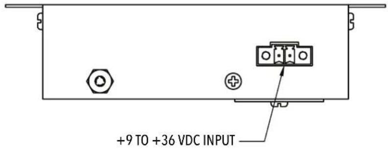
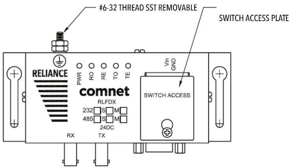
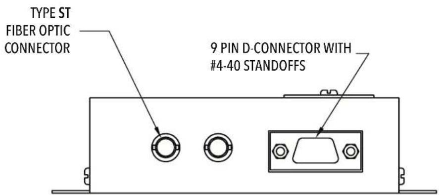
Figure 1 Elements of the Link/Repeater
INSTALLATION AND OPERATION MANUAL RLFDX485 SERIES
Each RLFDX485(M,S)/(48DC,HV) Link/Repeater consists of the following elements.
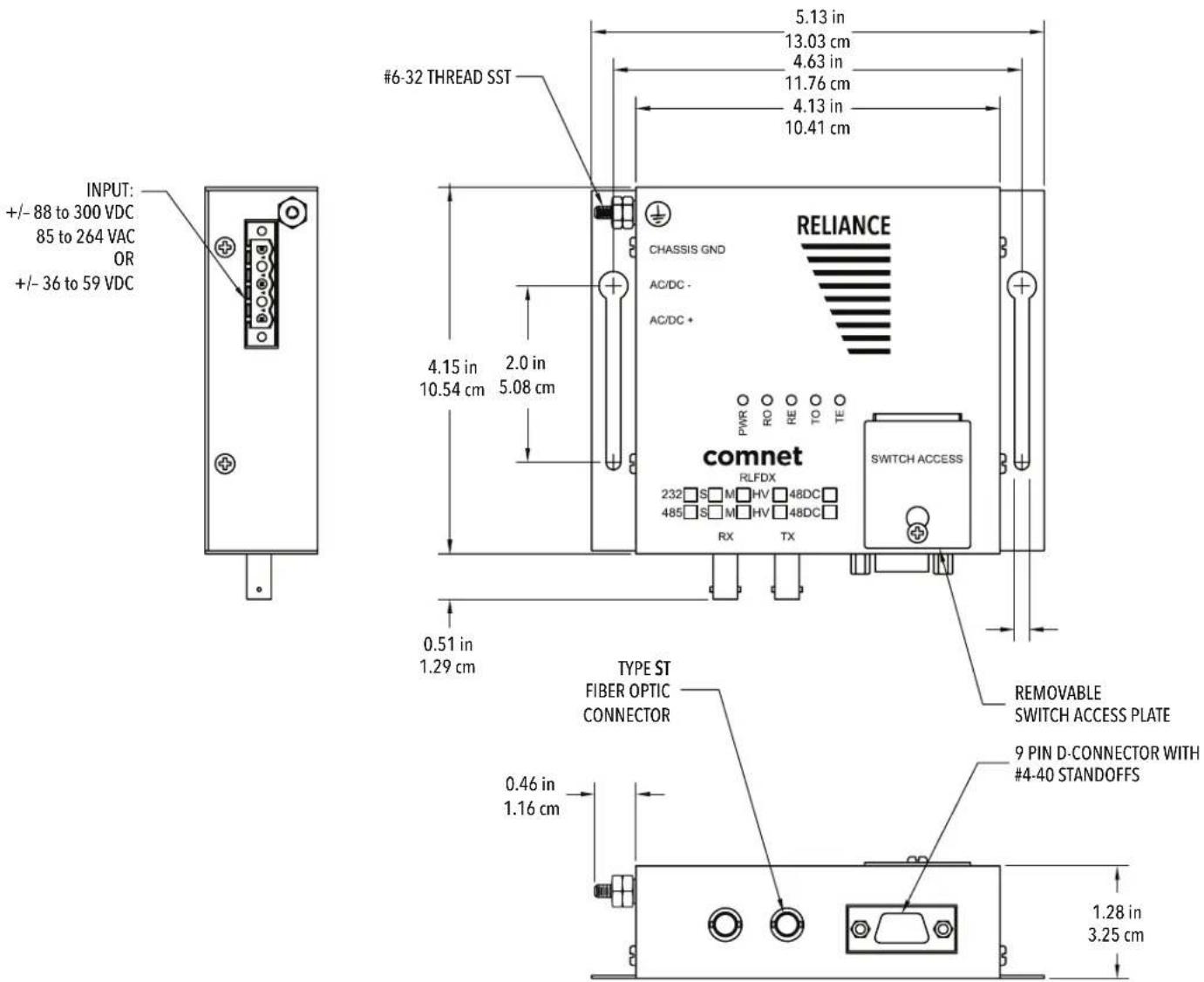
Figure 1 Elements of the Link/Repeater
1.2.1 9 Pin Data Port D-connector
The Link/Repeater connects directly to an IED's RS-422 or RS-485 communication port. The pin-out configuration of the Link/Repeater is shown in Figure 2. If the IEDs port is not a 9-Pin Dconnector, or if the IEDs pin-out configuration differs, a suitable adapter is required. Note: The operating voltages specified in the table below for Pin 9 are applicable only to models RLFDX485M2/24DC & RLFDX485S2/24DC
HD MODE FD MODE
- 1 Trans/Rec Data - B/B' • 1 Transmitted Data - [B] (Link input)
- 2 Trans/Rec Data + A/A' • 2 Transmitted Data - [B] (Link input)
- 3 No Connection • 3 Received Data - [B'] (Link output)
- 4 No Connection • 4 Received Data + [A'] (Link output)
- 5 Signal Ground
- 5 Signal Ground
- 6 Earth Ground
- 6 Earth Ground
- 7 Repeat Enable / Disable • 7 Repeat Enable / Disable
- 8 Optical Enable / Disable • 8 Optical Enable / Disable
- 9 +9 to +15 VDC Power (Pin 5 GND) • 9 +9 to +15 VDC Power (Pin 5 GND)
Figure 2 Data Port Pin Assignments
1.2.2 Switch Settings
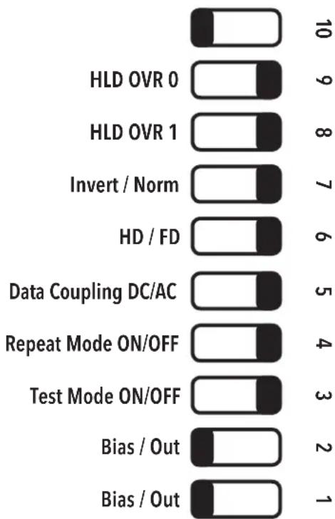
bar
| Category | Value | |---|---| | HLD OVR 0 | 10 | | HLD OVR 1 | 9 | | Invert / Norm | 8 | | HD / FD | 7 | | Data Coupling DC/AC | 6 | | Repeat Mode ON/OFF | 5 | | Test Mode ON/OFF | 4 | | Bias / Out | 3 | | Bias / Out | 2 | | Bias / Out | 1 |Figure 3. Switch Settings (Factory Defaults)
1.2.3 HD / FD Switch
The HD/FD Switch adapts the Link/Repeater to accept independent transmit and receive channels or a single shared transmit/receive channel.
HD: In this position, the Link/Repeater accepts a shared transmit/receive communication channel such as normally associated with RS-485 2-wire standards. When in the HD position, the Link/Repeater is "listening" for data signals both optically and electrically and automatically switches to the correct state. This position is normally used for RS-485 2-wire connections and only half-duplex or simplex communication is available. Multi-drop networks may be either Peer-to- Peer or Local / Remote.
FD: When independent transmit and receive electrical channels are available, select the FD position. This will normally be used for RS-422 or RS-485 4-wire standards. The Link/Repeater can support full duplex, half duplex or simplex communication in this position. Multi-drop networks may only be Local / Remote.
1.2.4 Repeat Switch
The Repeat switch enables the repeater function in the "ON" position and disables it in the "OFF" position.
REP: The repeater function available in the Link/Repeater is enabled. This function converts the optical signal received on the R optical port to an electrical signal and delivers this signal to the appropriate pins of the 9-Pin connector, as well as, re-transmits the signal optically out the Link/Repeater's T optical port.
OFF: The repeater function available in the Link/Repeater is disabled. The Link/Repeater converts the optical signal received on the R optical port to an electrical signal and delivers this signal to the appropriate pin of the 9-Pin connector, and does not re-transmit the signal optically out the Link/Repeater's T optical port.
1.2.5 Logic Inversion Switch
Use of this feature is required when optically interconnecting IEDs using RS-232 to IEDs using RS-422 or RS-485, or IEDs that have biasing that pulls the "A" (+) line high and the "B" (-) line low during the quiescent state. (Refer to Section 3.5)
1.2.6 Input Bias Switch
The Biasing resistor switch selects electrical input biasing. Biasing on RS422/485 inputs provides the ability for the inputs to a device (the Link/Repeater) to be in a known electrical state if the outputs that are connected to it go into a Tri-State (non driving) condition. Pins marked B or - are pulled to +5 volts and pins marked A or + are pulled to Signal Ground. The default for the biasing resistors is 330 Ohms, optionally no biasing can be selected.
Bias: 330 Ohm Biasing resistors. This is equivalent to 9 loads when configuring a bus network configuration.
Out: No biasing resistors. This is the equivalent to 1 load when configuring a bus network. This
INSTALLATION AND OPERATION MANUAL RLFDX485 SERIES
setting should be used on at least one Link/Repeater if there are 2 or more electrically connected IED's in a copper bus network segment.
1.2.7 Input Data Coupling Switch
The Data Coupling switch selects the electrical input conditioning, the AC position selects capacitively coupled, the DC position is directly coupled.
AC: AC coupling has a minimum incoming data requirement of 1200 baud due to the capacitive coupling. This option blocks DC electrical levels should the device connected fail and 'stuck in a high level'. There is a 35 ms timeout for "stuck" output pins, after this time out the link returns to LED off state.
DC: DC coupling allows DC logic levels to be transmitted over the fiber network, care must be taken to guarantee that when any device stops transmitting packets that the input level returns to a state that allows the T receptacle (emitter) to turn off. If it does not and the IED is part of a loop, bussed or star network, the first device to transmit blocks all other devices on the network from transmitting. *Single-Mode units cannot be DC coupled.
1.2.8 Enable Holdover Switch
Since the RLFDX485 Series Link/Repeaters are protocol and baud rate independent, we have no way of determining the end of a word or packet, and therefore, when to tri-state the RS-422/485 driver. To overcome this obstacle, we drive '1' data bits for the full length of the bit and we drive '0' data bits for a pre-determined time. After that, the bias resistors hold the line in the '0' state. In most installations, the bias resistor circuit provides enough current for reliable communications, but in some cases (e.g. when our Link is electrically connected to many receivers) data errors can occur. We provide two dipswitch positions for the user to select one of four enable holdover times: 4μs (8 bit times at 2Mbps, the same as the previous generation Dymec/Garretcomm 5845/46 links), 71μs (8 bit times at 112Kbps), 833μs (8 bit times at 9.6Kpbs), and 8mS (8 bit times at 1Kbps) for the user to rectify this situation (See Figure 4). Extending the enable holdover time can improve the reliability of communications, but care must be taken to ensure that the enable holdover time does not exceed the minimum interpacket gap in that particular installation The factory default setting is 4μs.
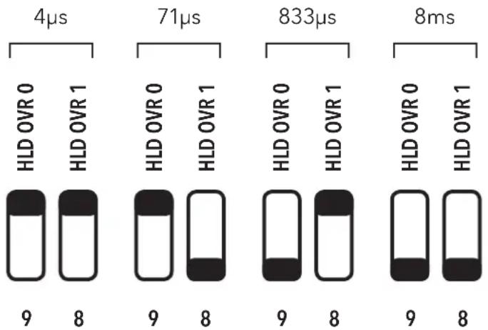
bar
| Time | HLD OVR 0 | HLD OVR 1 | |------|-----------|-----------| | 4μs | 9 | 8 | | 71μs | 9 | 8 | | 833μs| 9 | 8 | | 8ms | 9 | 8 |Figure 4. Enable Holdover Switch Settings
1.2.9 Test Mode Option Switch
ComNet™ RLFDX485 Series Link/Repeaters are provided with this switch to allow users who wish to test the fiber connections of the link with a built in diagnostic mode. This mode sends a 1KHz signal out the transmit port as well as looping back the copper port (pins 2 to 4 and pins 1 to 3) for diagnostic purposes. The loop back option for the copper/electrical port of the Link/Repeater is only available for Full Duplex mode.
1.2.10 Optical Ports
There are two optical ports: T and R. The T optical port transmits data signals optically to the next Link/Repeater. The R port receives the optical data signal from another Link/Repeater's T optical port. Each optical port is fitted with a type-ST connector for connecting to the fiber optic cable.
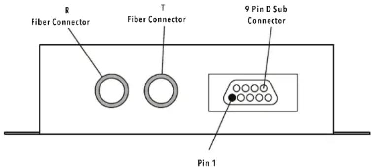
Figure 5 Optical Ports and Electrical Port
1.2.11 Diagnostic LEDs
Each Link/Repeater is equipped with four diagnostic/status indicating LEDs. They represent the electrical transmit (TE), optical transmit (TO), electrical receive (RE), and optical receive (RO) paths. These LEDs, when illuminated, indicate that the appropriate path is active. When the Link/ Repeater is transmitting, both TE and TO LEDs will illuminate to indicate the transmit path is active. When the Link/Repeater is receiving light signals, both RO and RE LEDs will illuminate. If the unit is in the repeat mode and receiving light, the RO, RE and TO LEDs will illuminate, as the signal is being retransmitted out of the optical port, as well as being outputted to the electrical data D-connector. LEDs only illuminate when the path is active; powering on the unit does not illuminate the LEDs unless their path is active. When data is present on the paths, the LEDs may flicker; this is a normal condition. The diagnostic LEDs may also be used for troubleshooting, by observing that the illumination of the LEDs corresponds with activity in the unit. See Figure 6 for LED patterns and signal paths.

flowchart
graph TD
    A["2 2 23"] --> B["PWR"]
    A --> C["RO"]
    A --> D["RE"]
    A --> E["TO"]
    A --> F["TE"]
    G["3"] --> H["PWR"]
    G --> I["RO"]
    G --> J["RE"]
    G --> K["TO"]
    G --> L["TE"]
    M["3"] --> N["PWR"]
    M --> O["RO"]
    M --> P["RE"]
    M --> Q["TO"]
    M --> R["TE"]
Normal Transmission Normal Receive Normal Repeat
Figure 6. Diagnostic LED patterns and signal paths
NOTE: The LEDs only illuminate when there is data traffic, and are not illuminated during signal quiet times. The LEDs may flicker; this is normal operation.
1.2.12 Power Connections
1.2.12.1 Powering Models RLFDX485M2/24DC & RLFDX485S2/24DC
Model RLFDX485M2/24DC may be powered either through pin 9(+) and pin 5 (Ground) of the 9-Pin D connector, or the external power connector located on the rear of the unit:
- When powering the RLFDX485M2/24DC via pin 9 of the D-connector, the IED must supply at least 250 mA, or 340mA for the RLFDX485S2/24DC. This voltage should be regulated, and within a range of +9 to +36 Vdc.
- When powered from the external power connector located on the rear of the unit, the operating voltage may be unregulated.
CAUTION: Regardless of the power connection used, Model RLFDX485M2/24DC requires 250 mA, and 340 mA for the RLFDX485S2/24DC, within a range of +9 to +36 VDC. A power supply not capable of supplying 250 mA over the entire operating temperature range may cause the Link/Repeater to malfunction.
Note: Connection of the no. 6-32 ground stud located on the rear of the unit to station ground is optional for models RLFDX485M2/24DC and RLFDX485S2/24DC.
1.2.12.2 Powering Models RLFDX485M2/48DC & RLFDX485S2/48DC
48 Volt DC Models RLFDX485M2/48DC and RLFDX485S2/48DC operate from any source of 36 to 59 VDC. These units include an internal regulated power supply. The supply voltage may be unregulated, but the circuit must be capable of providing a minimum of 250 mA for the RLFDX485M2/48DC, and 340 mA for the RLFDX485S2/48DC.
WARNING: Both models provide a no. 6-32 screw ground stud and a power connector on the side of the housing. Be certain to connect a suitable earth ground to the grounding stud on the side of the Link/Repeater. Remove the power plug from the power connector of the Link/ Repeater. Connect the power lines to the power plug, being careful not to leave any wire strands exposed, and replace the power plug.
As the DC input is isolated from ground, these units may be operated from either positive or negative DC sources.
1.2.12.3 Powering Models RLFDX485M2/HV and RLFDX485S2/HV
Models RLFDX485M2/HV and RLFDX485S2/HV operate from any source of 85 to 264 VAC (50/60 Hz), or 88 to 300 VDC. They include an internal voltage regulated power supply, and may be connected directly to the AC line, or station battery bus power. The station battery bus voltage may be unregulated, but the circuit must be capable of providing a minimum of 35mA for model RLFDX485M2/HV, or 50mA for the RLFDX485S2/HV.
Both models provide a no. 6-32 ground stud and a power connector on the side of the housing. Be certain to connect a suitable earth ground to the grounding stud on the side of the Link/Repeater. Remove the power plug from the power connector of the Link/Repeater. Connect the power lines to the power plug, being careful not to leave any wire strands exposed, and replace the power plug.
As the high-voltage DC input is isolated from ground, these units may be operated from either positive or negative DC sources.
This power input to the RLFDX485-series is Surge Withstand Protected to IEC 61000-4-4, EN61000-4-5 Standard and ANSI/IEEE C37.90.1-1989.
WARNING: When installing a Model RLFDX485M2/48DC, RLFDX485S2/48DC, RLFDX485M2/HV or a RLFDX485S2/HV Link/Repeater, an earth ground must be attached to the ground stud on the side of the case before connecting to operating power. Failure to follow this procedure may result in an electrical shock hazard to personnel.
Note: Connection of the no. 6-32 ground stud located on the rear of the unit to station ground is optional for models RLFDX485M2/24DC and RLFDX485S2/24DC.
INSTALLATION AND OPERATION MANUAL RLFDX485 SERIES
1.2.13 Peripheral Equipment
1.2.13.1 IED
An IED is any intelligent electrical device such as a computer, RTU, PLC, "smart" meter, protective relay, etc., that has the ability to communicate data via an RS-422 or RS-485 format. The IED should have a communication port for the connection of the Link/Repeater. If the IEDs communication port connector will not permit the Link/Repeater to be plugged in directly, a suitable adapter must be made to accommodate the connection. Care should be taken to ensure that the correct signals are connected to each other. See Figure 2 for the Link/Repeater pin signal assignments. Check your IEDs equipment manual for its signal assignments.
The IED must also have intelligent software to execute the data communication. This intelligence needs to logically manage the data and signal traffic, including any addressing, token passing, handshaking, data formatting, and scheduling.
1.2.13.2 Fiber Optic Cable (FOC)
The selection of the fiber optic cable is important. High quality cable will ensure the maximum performance of the Link/Repeater. Important factors to consider are the manufacturer's specification on optical attenuation per unit length, optical attenuation due to aging, diameter, and tensile strength. Choosing the best quality FOC for your installation is important.
Model RLFDX485M2/24DC, RLFDX485M2/48DC, and RLFDX485M2/HV Link/Repeater units are designed for use with type-ST cable terminations, and are compatible with multimode FOC ranging from 50 m to 200 m.
Model RLFDX485S2/24DC, RLFDX485S2/48DC, and RLFDX485S2/HV Link/Repeater units are designed for type-ST cable terminations, and are compatible with single-mode FOC ranging from 5 m to 13 m.
2. Configurations, Operation, and Installation
The RLFDX485 series of Link/Repeaters may be connected in a Point-to-Point configuration, in a Local/Remote Loop, in a Peer-to-Peer Loop, depending upon the requirements of the overall communication system.
These models are designed to accept electrical inputs per RS-422 and RS-485 standards.
The RLFDX485 Series is designed to accept differential electrical inputs per RS-422 and RS-485 standards. Various implementations of these electrical standards can result in different types of electrical circuits. The RS-422 standard and the RS-485 4-wire standard are normally associated with independent and separate transmit and receive channels. In Multi-drop networks, these standards allow Local / Remote operation only.
The RS-485 2-wire standard generally uses a bi-directional, shared transmit/receive channel. In multi-drop networks, either Peer-to-Peer or Local / Remote operation is possible. The HD/FD switch on each unit configures the Link/Repeater to accept either condition.
When the HD/FD switch is in the HD position, the Link/Repeater operates in half duplex mode only and both transmit and receive signals share pins 2 (A) and 1 (B).
In the FD position, Link/Repeater pins 2 (A) and 1 (B) connect to the IED's transmit channel. Link/Repeater pins 4 (A') and 3 (B') connect to the IED's receive channel.
NOTE: Some IEDs use "+" and "-" labels for their signals. A and A' are "+" and B and B' are "-"
It is also possible to optically connect the Link/Repeaters together within the same optical network when IEDs with different electrical data formats are utilized. For example, where one IED is communicating via RS-232, another IED is communicating with RS-422 or RS-485, etc., the data format translation between the IEDs is performed automatically in this application.
APPLICATION NOTE:
Fully electrically, mechanically, and optically identical to and backward-compatible with the Garrettcom/Dymec 5843, 5844, 5845, and 5846 Series, products in the ComNet RLFDX Series may directly replace a Dymec unit anywhere within the network, and can optically communicate to each other, eliminating the need for external format translation interface devices, provided all connected devices are operating at the same data rate.
2.1 Point-To-Point Configuration
For Point-to-Point operation, two Link/Repeaters are optically connected to each other.
This configuration permits full-duplex communication (simultaneous transmitting and receiving), half-duplex communication (sequential transmitting and receiving), and simplex (one device transmitting or receiving only).
APPLICATION NOTE:
In Point-to-Point operation, the communication logic (control software) of the IEDs must manage:
- The transmission of data signals.
- The reception of data signals.
- Any "handshaking" required must be accomplished through software.
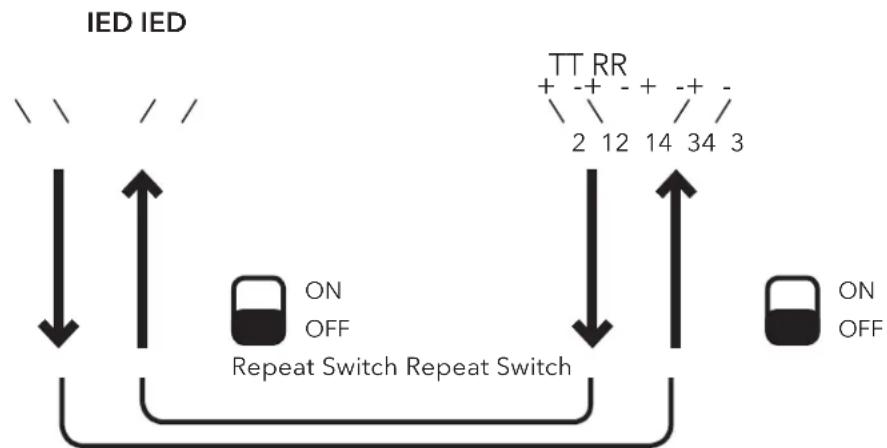
flowchart
graph TD
    A["IDE"] --> B["IEC"]
    B --> C["ON OFF"]
    C --> D["Repeat Switch"]
    D --> E["TT RR"]
    E --> F["+ - + - + - + - / /"]
    F --> G["2 12 14 34 3"]
    G --> H["ON OFF"]
    H --> I["OUT"]
    style A fill:#f9f,stroke:#333
    style B fill:#ccf,stroke:#333
    style C fill:#cfc,stroke:#333
    style D fill:#fcc,stroke:#333
    style E fill:#cff,stroke:#333
    style F fill:#ffc,stroke:#333
    style G fill:#cfc,stroke:#333
    style H fill:#fcc,stroke:#333
    style I fill:#cfc,stroke:#333
Figure 7. Point-to-Point Configuration
The HD/FD switch is set to the position that satisfies the IED that is connected to the Link/Repeater.
This configuration permits half duplex communication (sequential transmitting and receiving) and simplex (transmitting or receiving only) when the HD/FD switch is in either position. Full duplex is only available for circuits with independent transmit and receive channels where the HD/FD switch is placed in the FD position.
2.1.1 Installation
- Set the HD/FD Switch to the appropriate position for each Link/Repeater and its respective IED.
- Set the Repeat Switch on all of the units to the "OFF" position.
- Connect the Link/Repeater to the IEDs RS-422 or RS-485 communication port (including any adapter that may be needed).
- Connect the Fiber Optic Cables (T of one device to R of the second device).
- Connect power to the Link/Repeater as follows:
A) If models RLFDX485M2/24DC or RLFDX485S2/24DC are to be powered through the D-connector (+9 to +36 VDC on pin 9 referenced to Pin 5, signal ground) then the unit is energized when it is connected to the D-connector (the power LED will illuminate).
B) Connect the power leads to the power connector, and then energize the power source. The unit is now powered (the power LED will illuminate).
WARNING: When installing a Model RLFDX485M2/48DC, RLFDX485S2/48DC, RLFDX485M2/HV, or RLFDX485S2/HV Link/Repeater, an earth ground must be attached to the no. 6-32 ground stud on the side of the housing before connecting to operating power. Failure to follow this procedure may result in an electrical shock hazard to personnel.
- Verify operation using the diagnostic/status indicating LEDs. (See Figure 5).
NOTE: Connection of the no. 6-32 ground stud located on the rear of the unit to station ground is optional for models RLFDX485M2/24DC and RLFDX485S2/24DC
NOTE: The LEDs only illuminate when there is signal traffic and are not illuminated during signal quiet times. The LEDs may flicker; this is normal operation..
NOTE: If during signal quiet time, TE and TO are illuminated, it suggests either a polarity reversal (pins 1 & 2) or that the IED is biased pulling the "A" (+) line with respect to the "B" (-) line. After checking the polarity on the connections, refer to section 3.5.
APPLICATION NOTE
The Point-to-Point concept can also be used to create an optical bus network. This can be useful in those applications where the software in the Local has not been written in such a way that it can support the return of the transmitted echo that normally occurs in loop networks.
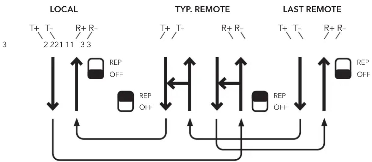
Note that all Remotes receive the Local's transmission, but only the polled Local hears the response from the addressed Remote. The Local must always be the first IED within the network.
Figure 8 shows the connections for a Local/Remote RS-422 "optical bus". Note that RS-422 Standards do not permit multiple transmitters to be connected together as they are not tri-stated. In this configuration, all Remote units hear the Local unit's transmission, but only the Local hears the response from the addressed remote. The Local must always be the first IED in the network.
INSTALLATION AND OPERATION MANUAL RLFDX485 SERIES
flowchart
graph TD
    A["LOCAL"] --> B["TYP. REMOTE"]
    B --> C["LAST REMOTE"]
    subgraph LOCAL
        D1["T+"] --> E1["2"]
        D2["T-"] --> E2["2"]
        D3["R+"] --> E3["11"]
        D4["R-"] --> E4["3"]
        D5["3"] --> E5["3"]
    end
    subgraph TYP. REMOTE
        F1["T+"] --> G1["//"]
        F2["T-"] --> G2["//"]
        F3["R+"] --> G3["//"]
        F4["R-"] --> G4["//"]
    end
    subgraph LAST REMOTE
        H1["T+"] --> I1["//"]
        H2["T-"] --> I2["//"]
        H3["R+"] --> I3["//"]
        H4["R-"] --> I4["//"]
    end
    E1 <--> F1
    E2 <--> F2
    E3 <--> F3
    E4 <--> F4
    I1 <--> H1
    I2 <--> H2
    I3 <--> H3
    I4 <--> H4
    H1 <--> I4
    H2 <--> I4
    H3 <--> I4
    H4 <--> I4
    I4 <--> H1
    I4 <--> H2
    I4 <--> H3
    I4 <--> H4
Figure 8. RS-422 Bus Configuration
FD is selected on all Link/Repeaters
All Remotes hear the Local's Poll. Only the Local hears the response.
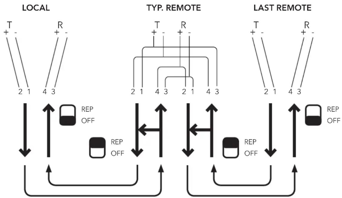
Figure 9 depicts an RS-485 multiple drop "optical bus" for both 4-wire and 2-wire systems. The 4-wire system is a Local/Remote configuration. All the Remotes hear the Local's poll, but only the Local can hear the addressed Remote's response and the Local must be the first IED in the network. However, in the 2-wire configuration, the system is capable of operating as Peer-to-Peer or Local/Remote. All IEDs hear all communications, and the Local may be located at any point in the network.
flowchart
graph TD
    subgraph LOCAL
        A1["T"] --> B1["2 1"]
        A2["R"] --> B2["4 3"]
    end
    subgraph TYP. REMOTE
        C1["T"] --> D1["2 1"]
        C2["R"] --> D2["4 3"]
        C3["2 1"] --> D3["2 1"]
        C4["4 3"] --> D4["4 3"]
    end
    subgraph LAST REMOTE
        E1["T"] --> F1["2 1"]
        E2["R"] --> F2["4 3"]
        E3["2 1"] --> F3["4 3"]
    end
    B1 --> G1["REPOFF"]
    B2 --> G2["REPOFF"]
    D1 --> H1["REPOFF"]
    D2 --> H2["REPOFF"]
    D3 --> H3["REPOFF"]
    F1 --> I1["REP OFF"]
    F2 --> I2["REP OFF"]
    H1 --> J1["REP OFF"]
    H2 --> J2["REP OFF"]
    H3 --> J3["REP OFF"]
    I1 --> K1["REP OFF"]
    I2 --> K2["REP OFF"]
    J1 --> L1["REP OFF"]
    J2 --> L2["REP OFF"]
    K1 --> M1["REP OFF"]
    K2 --> M2["REP OFF"]
    L1 --> N1["REP OFF"]
    L2 --> N2["REP OFF"]
Figure 9. 4-Wire RS-485 Local/Remote Configuration
FD is selected on all Link/Repeaters
All Remotes hear the Local's Poll. Only the Local hears the response.
INSTALLATION AND OPERATION MANUAL RLFDX485 SERIES
Figure 10. 2-Wire RS-485 Local/Remote Configuration HD is selected on all Link/Repeaters
All IEDs have the ability to hear and respond to each other.
NOTE Before constructing a loop network, be sure that the software protocol of the Local is capable of managing the receipt of its own echoed transmission. If it cannot, then use a Point-to-Point configuration only between devices in an optical bus network topology.
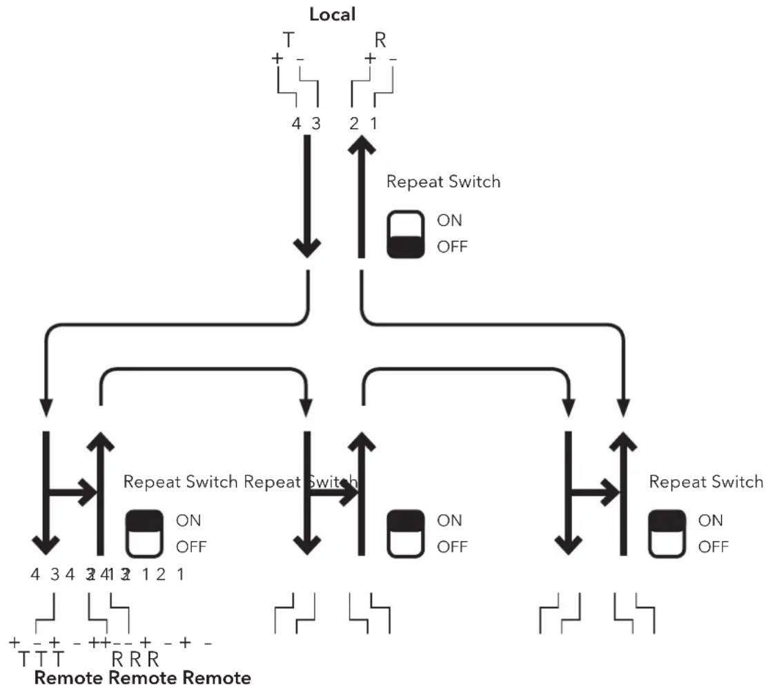
This configuration supports a network that requires more than two IEDs to be communicating. In a Local/Remote loop system, one IED acts as a Local at all times and addresses or "polls" each of the other connected IEDs individually. Each Remote receives the same transmission from the Local IED but only responds when it recognizes its address in the polling message.
flowchart
graph TD
    A["Local"] --> B["T + - 4 3"]
    A --> C["R + - 2 1"]
    B --> D["Repeat Switch ON OFF"]
    C --> E["Repeat Switch ON OFF"]
    D --> F["Repeat Switch ON OFF"]
    E --> G["Repeat Switch ON OFF"]
    F --> H["Remote Remote Remote T T T R R R"]
    G --> I["Remote Remote Remote R R R"]
    H --> J["Remote Remote Remote T T T R R R"]
    I --> K["Remote Remote Remote R R R"]
Figure 11. Local/Remote Loop Configuration
The Local must have its Repeat Switch in the "OFF" position. When it transmits a request from its T optical port, it will receive the echo of its request at its R optical port. This request has gone around the loop, and has been repeated by each Remote in the loop. In this mode, the Local does not repeat (re-transmit) any of these received signals optically around the loop, because its Repeat Switch is in the "OFF" position.
INSTALLATION AND OPERATION MANUAL RLFDX485 SERIES
Note: The communication logic and control software of the Local IED must be able to manage the receipt of its echoed request. The receipt of the echo can be used in conjunction with a watchdog timer to continuously verify loop integrity.
When addressed, the Remote will transmit an appropriate response. Each Link/Repeater connected to a Remote IED must have its Repeat Switch set in the "ON" position. In this mode, all signals received on a Remote's R optical port are delivered to the IEDs communication port, and at the same time repeated out the T optical port to the next device in the loop. If an IED determines that this request requires a response, then the Link/Epeater transmits the IEDs response out the T optical port. The response is repeated at each Remote device, until it arrives at the Local.
When an IED is a Remote, it should not attempt to initiate a transmission while it is receiving a signal. Since signals being received are also being repeated at the same time, any attempts to transmit its response while receiving can corrupt both transmissions due to a data collision.
CAUTION: If a Remote IED attempts to transmit while receiving a message, a data collision will occur.
In Local/Remote Loop Operation, half duplex communication (sequential transmit and receive functions) is available. Only the Local can communicate full duplex (simultaneous transmit and receive) in a Local/Remote loop, provided its IED has independent Transmit and Receive channels, and the Link/Repeater HD/FD Switch is placed in the FD position.
APPLICATION NOTE
In a Local/Remote Loop Operation, the communication logic (control software) and the Local IED must manage:
1) The transmission to Remotes (including addressing).
2) The receipt of the echo of its transmissions.
3) The receipt of the Remote's response to its transmission.
4) The control of the Remotes to prevent the initiation of a transmission while receiving a signal.
2.2.1 Installation
- Set the HD/FD Switch to the appropriate position for each Link/Repeater and its respective IED.
- Set the Repeat Switch to the "OFF" position on the Local. Set the Repeat Switch to the "ON" position on each Remote.
- Connect the Link/Repeater to the IEDs RS-422 or RS-485 communication port (Including any adapter that may be needed).
- Connect the Fiber Optic Cables (T of one device, to R of the next device in the loop). Continue around the loop back to the Local, to close the loop.
- Connect power to the Link/Repeater as follows:
A) If the unit is to be powered through the D-connector (+9 to +36 VDC on pin 9 referenced to pin 5, signal ground), the unit will energize when it is connected to the D-connector (the power LED will illuminate).
B) If the unit is to be powered through the power connector: Connect the power leads and the power connector and then energize the power source. The unit is now powered (the power LED will illuminate).
WARNING
When installing a Model RLFDX485M2/48DC, RLFDX485S2/48DC, RLFDX485M2/HV, or RLFDX485S2/HV Link/Repeater, an earth ground must be attached to the no. 6-32 ground stud on the side of the housing before connecting to power. Failure to follow this procedure may result in an electrical shock hazard to personnel.
- The units are now installed and operating.
- Verify operation using the diagnostic/status indicating LEDs. (See Figure 5).
NOTE The LEDs only illuminate when there is signal traffic and are not illuminated during signal quiet times. The LEDs may flicker: This is normal operation.
2.3 Loop Operation - Peer-To-Peer Configuration
NOTE Before constructing a loop network, be sure that the software protocol is capable of managing the receipt of the echo of its own transmission. If it cannot, then use a Point-to-Point configurations only between devices in an optical bus network approach.
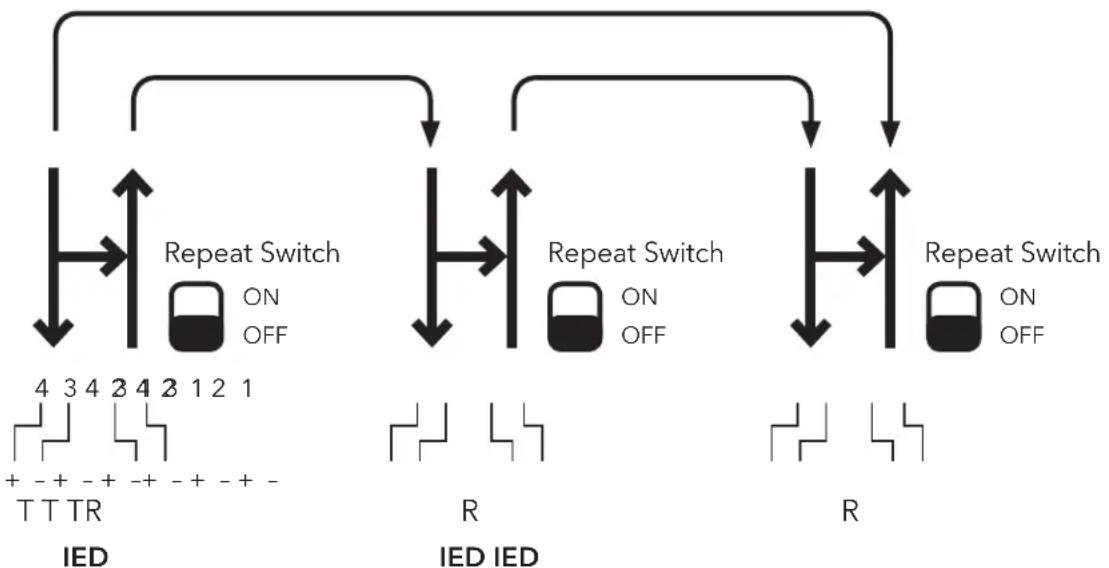
A Peer-to-Peer loop configuration is similar to the Local/Remote loop configuration, except that each IED in the loop is capable of locating the loop in a pseudo-Local/Remote loop. To achieve this, all models within the RLFDX series provide an electrical means of controlling the "Off/Repeat" function.
In this application, all Link/Repeaters are connected in a loop with their Repeat Switch in the "OFF" position. Each IED must be able to control pin 7 of the D-connector, to enable and disable the "ON" function. When an IED applies a low potential (less than 0.6 Vdc to pin 7), it enables the repeat function of the Link/Repeaters. This is equivalent to the Repeat Switch being in the "ON" position. When an IED wishes to become the loop Local, it raises the potential on pin 7 to a high potential (greater than 2.0 Vdc). This disables the Link/Repeaters' repeat function as if the Repeat Switch were in the "OFF" position.
NOTE: The communication logic and control software of the Local IED must be able to manage the receipt of its echoed request. The receipt of the echo can be used in conjunction with a watchdog timer to continuously verify loop integrity.
flowchart
graph TD
    A["Top Left"] --> B["Upward Switch"]
    B --> C["ON OFF"]
    C --> D["Bottom Right"]
    D --> E["Upward Switch"]
    E --> F["ON OFF"]
    F --> G["Bottom Left"]
    H["Bottom Right"] --> I["Upward Switch"]
    I --> J["ON OFF"]
    J --> K["Bottom Left"]
    style A fill:#f9f,stroke:#333
    style H fill:#f9f,stroke:#333
    style B fill:#ccf,stroke:#333
    style E fill:#ccf,stroke:#333
    style I fill:#ccf,stroke:#333
FIGURE 12. Peer-to-Peer Loop Configuration
When the potential on pin 7 is low, signals received on the R optical port are delivered to the IED, and are repeated out the T optical port to the next device in the loop. A high potential on pin 7 causes signals received on the R optical port to be delivered to the IED only, and are not repeated out the T port. It is not necessary for a Remote unit to raise the potential of its pin 7 to transmit.
After an IED has completed its tasks Localing the loop, it must return its pin 7 to a low potential, enabling its repeater function, and re-establishing loop continuity for the next IED that becomes loop Local.
INSTALLATION AND OPERATION MANUAL RLFDX485 SERIES
NOTE Powering and controlling pin 7 is ignored in all configurations except Peer-to-Peer loop operation.
Half-duplex communication is available with this configuration.
When an IED is in the Remote state, it should not attempt to initiate a transmission while it is receiving a signal.
Since signals being received are also being repeated at the same time, any attempt to transmit its response while still receiving, can corrupt both transmissions due to a data collision.
NOTE Any Link/Repeater that has its Repeat Switch in the "OFF" position and has a high potential on pin 7 will not repeat those signals received on its R optical port through its T port. Only transmissions initiated by its IED are transmitted through its T optical port.
APPLICATION NOTE
In Peer-to-Peer loop operation, the communication logic (control software) and the Local IED must manage:
- The transmission to Remotes.
- The receipt of the echo of its transmissions.
- The receipt of the Remote's response to its transmission.
- The control of pin 7 located on the D-connector.
- The control of the Remotes to prevent the initiation of a transmission while receiving a signal.
2.3.1 Installation
- Set the HD/FD Switch to the appropriate position for each Link/Repeater and its respective IED.
- Set the Repeat Switch on all the units to the "OFF" position.
- Connect the Link/Repeater to the IEDs RS-422 or RS-485 communication port (Including any adapter that may be needed).
- Connect the Fiber Optic Cables (T of one device to R of the second device). Continue around the loop to complete the loop.
- Connect power to the Link/Repeater as follows:
A) If the unit is to be powered through the D-connector (+9 to +36 VDC on pin 9, referenced to pin 5, signal ground), the unit is energized when it is connected to the D-connector (the power LED will illuminate).
B) If the unit is to be powered through its power connector: Connect the power leads and the power connector, and then energize the power source. The unit is now powered (the power LED will illuminate).
WARNING: When installing a Model RLFDX485M2/48DC, RLFDX485S2/48DC, RLFDX485M2/HV or RLFDX485S2HV Link/Repeater, an earth Ground must be attached to the no. 6-32 ground stud on the side of the case before connecting to power. Failure to follow this procedure may result in an electrical shock hazard to personnel.
Note: Connection of the no. 6-32 ground stud located on the rear of the unit to station ground is optional for models RLFDX485M2/24DC and RLFDX485S2/24DC.
- The units are now installed and operating.
- Verify operation using the diagnostic LEDs. (See Figure 5).
NOTE The LEDs only illuminate when there is signal traffic and are not illuminated during signal quiet times. The LEDs may flicker. This is normal operation.
3. Applications
When planning a system using any RLFDX485-series Link/Repeaters, the following system parameters should be considered:
»Data Rate
»Optical Budget, and the distance between connected units
»Number of units in a loop configuration
»Powering the Link/Repeaters
»Type of communication, including format
»Selection of Fiber Optic Cable (FOC)
3.1 Data Rate
All RLFDX485-series Link/Repeaters automatically support data rates from 1200 bits per second (AC-coupled is the factory default setting) to 2 Mb per second. No internal baud selection or setting is required. However, it is necessary that all connected IEDs within the network be set at the same data rate.
3.2 Optical Budget
The optical budget is a ratio of the receiver sensitivity to transmitter launched optical power; i.e., the amount of light loss available from the transmitter to the receiver. It is calculated on a log scale, so that a 3 dB loss is equal to one-half of the original power; 10 dB is one tenth of the original power; 20 dB is one hundredth, etc. Many different elements in the optical path or circuit can induce losses to the power of the signal. This attenuation must be taken into account when determining the maximum distance that the signal can be reliably transmitted. The major factor is the attenuation of the fiber optic cable. Cable attenuation is expressed as "X" dB per kilometer. Other factors of attenuation include FOC fittings (connectors/terminations, splitters, etc.) FOC diameter, and FOC aging over time.
Optical budget is the result of the expression:
$$ \text { Optical Budget } [ \mathrm{dB} ] = \frac {1 0 \times \log 1 0 \text { Receiver sensitivity } [ \mu \mathrm{w} ]}{\text { Launch Power } [ \mu \mathrm{w} ]} $$
Each RLFDX485M2/XX Multimode Link/Repeater has a typical optical budget of 19.5 dB. Each RLFDX485S2/XX Singlemode Link/Repeater has a typical optical budget of 19 dB.
3.2.1 Cable Attenuation Factors
The following cable factors must be applied as corrections to the optical budget.
3.2.1.1 Diameter
Multimode: FOC of different diameters will limit the available optical budget of a system due to different FOC core diameters. The 19.5 dB typical optical budget is applicable to 62.5μm diameter multimode FOC. Table 1 shows the correction factors to use on the available optical budget for different diameter cable.
Table 1
| FOC Diameter Factor |
| 50μm -3 dB |
| 100μm +4 dB |
| 200μm +7 dB |
Single mode: 19 dB of optical budget is typically available and is essentially consistent for standard singlemode fiber diameters.
3.2.1.2 Fittings
Adding additional splices, feed-throughs, or patch panels to the fiber optic cable plant will add losses to the available optical budget. Optical budget loss information is available from the manufacturer(s) of these components.
3.2.1.3 Aging
As the FOC ages, tiny cracks will form in the glass core of the fiber, resulting in an increase in the attenuation of the cable. The optical emitters age over time, causing a very slow reduction in their optical launch power. ComNet suggests that an optical loss margin buffer be applied to the calculated optical budget, to ensure proper operation due to aging of the network over a 20-year life span. A 2.5 dB to 3 dB loss factor is suggested to compensate for system aging over this 20 year period.
EXAMPLE: FOC is 62.5/125 μm multimode
100 kpsi rated 3 dB/km and 3 dB for aging
No other attenuating items in the circuit
initial: 19.5 dB Optical Budget
less: 3 dB aging
less: 0 dB for other circuit attenuation fittings
equals: 16.5 dB
divided by: 3 dB/km
equals: 5.5 km maximum distance of FOC between transmitter and receiver
NOTE: Fiber optic transmission radically extends transmission distances beyond the normal copper media RS-422 or RS 485 standards limits. The maximum usable optical transmission distance between Link/Repeaters must be calculated using the factors listed above.
3.2.2 Extending the Distance
Should the optical transmission distance between two devices exceed that calculated above, it is possible to insert a pair of Model RLFDX485 Series Link/Repeaters to function as stand-alone repeaters, powered but not connected to an IED. Two Link/Repeaters are necessary, one for each fiber path. The Repeat Switch of each unit is placed in the ON position. Serving as a repeater only, the 9 Pin D connector should have a protective cover over the pins. If it is a single mode unit, pin 5 (signal common) should be tied to pin 6 (earth ground).
3.3 Number Of Repeats
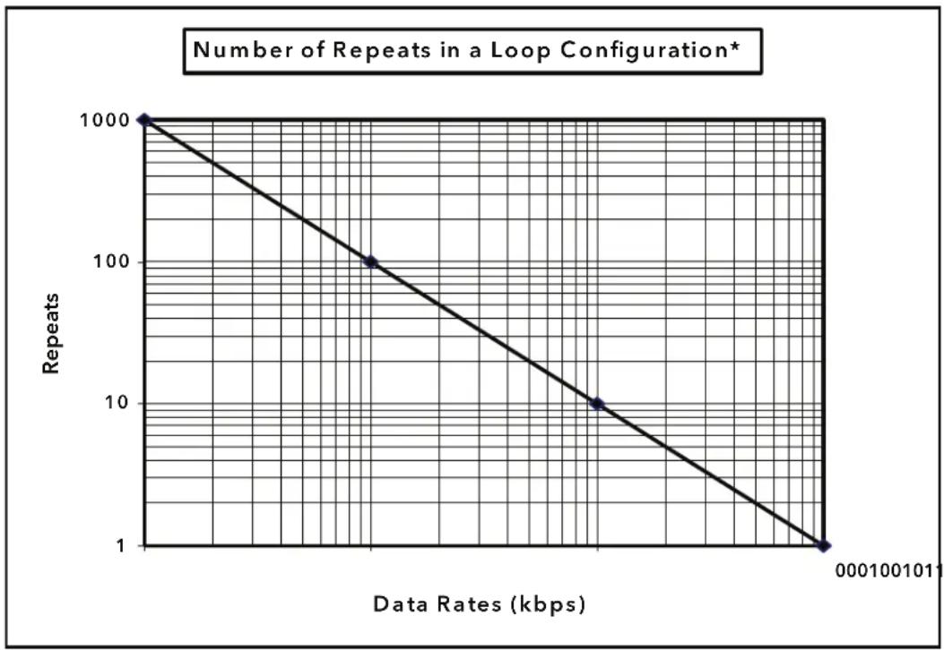
In a loop configuration, the maximum number of units that can be used as repeaters must be determined. A repeater is any unit that uses the repeat function of the Link/Repeater. All Remotes in a Local/Remote loop are considered repeaters. Three factors must be considered in calculating the maximum number of repeaters possible in a loop; the data rate (bits per second); the minimum required width of the original pulse echoed back to the Local; and the maximum/peak operating temperature.
line
| Data Rates (kbps) | Repeats | | ----------------- | ------- | | 0 | 1000 | | 100 | 100 | | 1000 | 1 |FIGURE 9. Number of Repeats
3.3.1 Effects of Data Rate
The number of repeaters is a linear inverse function to the data rate (i.e., more possible repeats at lower data rates). The data rate, or bits per second rate, determines what the original pulse width of each bit will be. The higher the data rate, the smaller the pulse width of each bit.
As the signal passes through a repeater, any distortion effect on the data signal is greater at higher data rates, due to smaller pulse widths then lower data rates.
3.3.2 Pulse Width Distortion
As the data signal is passed from repeater to repeater, there is a small change to the pulse width; this is defined as pulse width distortion. The amount of change that is tolerable corresponds to the percentage of original pulse width required by a particular communications system design. Typically, a communication system requires that the data word, or bit stream that each Remote IED receives, matches the signal originally generated by the Local, within some tolerance of pulse width distortion. High tolerance systems allow more pulse width distortion; therefore, more repeats are tolerated. Conversely, low tolerance systems allow fewer repeats in the loop.
Figure 9 shows the maximum number of repeats possible if 70% of the original pulse width is required by any IED within the loop. The acceptable percentage of the original pulse width is due to the requirements of the IEDs. If more of the original pulse width is necessary or less is allowable, then the number found in Figure 9 can be modified. Table 2 shows the factors to be used to correct the number of repeats found in Figure 10 for such cases.
Table 2
| % of Original Pulse Multiply Factor |
| 80% .67 |
| 60% 1.33 |
| 50% 1.67 |
3.3.3 Temperature Effect
At peak operating temperatures above 65^ C, the maximum number of repeats should be derated by 20%. At higher temperatures, the distortion caused by each repeat increases, reducing the maximum number of possible repeaters within the network.
EXAMPLE: Peak temperature of the system will be 70^ C
Data Rate: 9600 bps
60% of original pulse width possible
initial: 100 repeats (from Figure 10)
less: 20% de-rate for 70°C
times: 1.33 for 60% pulse width
equals: 100 × 0.8 × 1.33 = 106 repeats
3.4 Types Of Communication
The RLFDX-series of Link/Repeaters support the following types of asynchronous communications:
»Simplex - Transmission only or receive only
»Half-duplex - Sequential transmit and receive
»Full-duplex - Simultaneous transmit and receive
| Simplex | Half-Duplex | Full-Duplex |
Point-to-Point: (Repeat Switch "OFF") X X X
Local/Save Loop: Local (Repeat Switch "OFF") X X X
Local/Remote Loop: Remote (Repeat Switch "ON") X X
Peer-to-Peer Loop: Local (Repeat Switch "OFF" and pin 7 "high") X X X
Peer-to-Peer Loop: Remote (Repeat Switch "OFF" and pin 7 "low") X X
3.5 Logic Inversion Switch
The Logic Inversion Switch is located on the top of the unit and is standard on all RLFDX485 Series Link / Repeaters. This slide switch inverts the polarity and logic sense of all electrical transmit and receive signal states going to and from the 9-Pin D-connector. It is set toward the 9-Pin D-connector for the normal state (factory set default).
Every RLFDX485 Series Link/Repeater in the same optical network must have the Logic Inversion Switch set to the same position, so that the quiescent state results in no light in the fiber. This feature is required when optically interconnecting IEDs operating RS-232 and translating to IEDs operating RS-422 or RS-485; connecting to some RS-422 or RS-485 IEDs that employ non-standard logic to signal communication; or for IEDs that employ line biasing that can cause the light to be on in the quiescent state.
The RLFDX485 Series are designed to operate with no light in the fiber during the communication quiescent (quiet) state. Normal protocol for IEDs operating RS-422 and RS-485 formats is implemented, such that the quiescent state is achieved with the protocol at a logic low, producing a potential low output. Occasionally, RS-422 and RS-485 may have their output lines biased such that the "A" (+) is pulled high and the "B" (-) line is pulled low in the quiescent state. This situation will produce a "light on" situation in the fiber during the quiescent period. This condition is not desirable, and the Logic Switch must be set in the INV position to compensate for this condition.
In addition, the user may connect ComNet™ RLFDX232 Series Link/Repeaters to the RLFDX485 Series and achieve RS-232 to RS-422 or RS-485 format translation without the need for external converter devices. However, the following condition must be satisfied: In RS-232, the logic state is inverse to the physical layer, i.e. logic high produces a physical low. When connecting RS-232 protocol, this logic to physical layer inversion must be reversed, or it will cause a "light on" situation in the quiescent state in the RLFDX485 Series equipment. The Logic Switch can be set in the INV position to correct this situation.
3.6 Echo Control For 2-Wire RS-485 Local Units In Loop Configurations
The RLFDX485 Series are designed to continuously listen, both electrically and optically, for data signals. Since the path is shared for transmit and receive, only one function may occur at any given interval in time. The RLFDX485 is designed to give priority to data signals received optically, compared to those being transmitted electrically, assuming that the software logic is managing data traffic.
However, in loop configurations, a special situation occurs if the Local IED is operating 2-wire RS-485 (HD). The echo of its transmissions can be received back to the Local so fast that it arrives before the transmission is completed, and a data collision will occur. Echo control must be implemented for each 2 wire IED that can become a Local in any loop configuration.
A feature is provided to avoid this, and is implemented as follows. The Local must apply a high potential (>2.4 v, but less than 30v) to pin 8 to disable the optical receiving circuitry of its Link/Repeater while transmitting. After the Local has completed transmitting, plus a short time interval that allows for the echo to be completely blocked, the Local relinquishes control of the optical receive. The Local must then return pin 8 to a low potential (<0.8v) to re-enable its optical receiving circuitry. The Local is now ready to accept the response from its poll request. Use of this feature is not necessary for Remote units in loop configurations, or in Point-to-Point and Optical Bus configurations. Typically, the software management sets an interval of null time before a polled Remote initiates its response, and one-half to three quarters of this time interval can be used for the delay time before returning the Local to the optical receive enable state.
This feature is standard in all ComNet RLFDX485 Series Link/Repeaters.
3.7 Types Of Communication
RLFDX485 Series Link/Repeaters support the following types of asynchronous communications:
»Simplex - Transmission only or receive only
»Half-duplex - Sequential transmit and receive
»Full-duplex - Simultaneous transmit and receive
| HD/FD Switch in FD Position HD | /FD Switch in HD Position | |||||
| Simplex | Half-Duplex | Full Duplex | Simplex | Half-Duplex | Full Duplex | |
| Point-to-Point - Repeat Switch OFF ● | ●●●● | - | ||||
| Local/Remote Loop - Local Repeat Switch OFF | ●●●●● | - | ||||
| Local/Remote Loop - Remote Repeat Switch ON | ●● | - | ●● | - | ||
| Peer-to-Peer Loop - Local Repeat Switch OFF and Pin 7 LOW | ●●●●● | - | ||||
| Peer-to-Peer Loop - Remote Repeat Switch OFF and Pin 7 HIGH | ●● | - | ●● | - | ||
INSTALLATION AND OPERATION MANUAL RLFDX485 SERIES
3.9 Selection of Fiber Optic Cables (FOC)
Fiber optical cable is available in several construction types: Simplex, duplex, and breakout. FOC is also available in various diameters and tensile strengths.
4. Testing And Troubleshooting
4.1 Testing
Models RLFDX485M2/XX and RLFDX485S2/XX lend themselves to easy installation and testing. Testing the units requires transmitting and receiving data, or setting the Test Mode switch to ON while observing that the diagnostic/status indicating LEDs are illuminating in the proper sequence.
To test whether a unit is transmitting and receiving correctly, insert a short fiber jumper between the T and R optical ports, and transmit a signal (or turn the Test Mode Switch ON). Note that all four diagnostic LEDs should illuminate during communications (refer to Figure 5).
To test the units in a loop configuration, two Link/Repeaters are required. Connect a short fiber jumper from the T optical port of one Link/Repeater, to the R optical port of the other. Set the Repeat Switch for one of the units to ON, and the other to OFF. The unit with the Repeat Switch in the OFF position is the Local. Using the Local, transmit and receive (or use the Test Mode Switch in the ON position) through the other unit in the repeat mode. Observe that the diagnostic LEDs illuminate during communications (refer to Figure 5).
When a Link/Repeater is not connected to an IED and is in the "repeat" mode, Transmit (pin 2 or pin 3, depending on the position of the DCE/DTE switch) and Chassis Ground (pin 6) should be connected to Signal Common Ground (pin 5). This will prevent any spurious noise from being induced into the fiber optic loop circuit while servicing an IED.
Single-Mode Models RLFDX485S2/24DC, RLFDX485S2/48DC, and RLFDX485S2/HV Only:
When not connected to an IED, and in the repeat mode, the Link/Repeater should have Chassis Ground (pin 6) connected to Signal Common/Ground (pin 5). If these pins are not tied together, noise could be induced into the fiber loop. This is also necessary when servicing an IED in order to keep the fiber loop and the Link/Repeater operational.
WARNING: The jumper connecting Chassis Ground and Signal Common/Ground should be disconnected before reconnecting Models RLFDX485S2/24DC, RLFDX485S2/48DC, or RLFDX485S2/HV to an IED.
If interconnecting an RS-485 Link/Repeater optically to an RS-232 Link/Repeater, the NORM / INV switch must be in the INV position.
If the IED's design biases A ("+") high and B ("-") low (a "steady" illuminated TE light, with no data flowing, will indicate this), then the NORM / INV switch must be set to the INV position.
If a Local of a Local/Remote loop is operating in the HD mode (RS-485), refer to Section 3.6 for special system requirements for the control of the echo.
4.2 Troubleshooting
If the unit does not work properly, refer to the set up instructions in this guide, and use the following check list:
»Is the unit properly powered?
Verify the unit is receiving the correct power.
Is the Power LED on?
If required, make sure power from D-connector is present on Pin 9.
» Check that the indicating LEDs are responding to the optical and electrical activity.
» Is the unit mated properly to the IED? If an adapter is used, check that pin assignments are connected correctly.
Are the fiber cables connected properly? T to R; not R to R, or T to T.
Are the HD/FD, the Repeat, and the NORM/INV switches set to the proper positions for the application?
» Determine that the IED's originating signal is within standards.
NOTE: If the Link/Repeater is not connected directly to an IED, determine that the electrical signal received by the Link/Repeater is not corrupt. The Link/Repeater only repeats the signal it is given, it does not re-clock or re-generate the signal.
» Review the IED's software and protocols. Does the IED have physical handshaking requirements, and have the appropriate settings on the IED been made to compensate for these requirements?
»Consult factory.
NOTE: The LEDs only illuminate when there is signal traffic, and are not illuminated during signal quiet times. The LEDs may flicker. This is normal operation.
NOTE: If during quiet time, TE and TO are illuminated, it suggests either a polarity reversal (pin 2 with pin 1) or that the IED is biased pulling the "A" (+) line with respect to the "B" (-) line. After checking the polarity on the connections, refer to Section 3.5.
The diagnostic LEDs may flicker when data is passing. This is normal operation.
NOTE: Link/Repeaters contain no serviceable parts. Opening the unit will void the warranty.
5. Specifications
5.1 Electrical and Optical Specifications
All Specifications over entire Operating Temperature Range. All Specifications are subject to change without notice.
| Multimode RLFDX485M2/24DC | RLFDX485M2/48DC & RLFDX485M2/HV | |
| Optical Budget Typical 19.5 dB 19.5 dB | ||
| Output power Typical -10.5 dBm peak -10.5 dBm peak | ||
| Receiver Sensitivity Typical -30 dBm peak -30 dBm peak (62.5/125 Multimode) (62.5/125 Multimode) | ||
| Wavelength | 850nm | 850nm |
| Connector Type | ST | ST |
| Compatible Fiber Type | Multimode(50-200μm) | Multimode(50-200μm) |
| Configuration (Switches) | HD/FDAC/DC CoupledLink/RepeatHold-Over (×2)Invert / NormTest ModeBias (×2) | HD/FDAC/DC CoupledLink/RepeatHold-Over (×2)Invert / NormTest ModeBias (×2) |
| Data Rate | DC to 2Mbps | DC to 2Mbps |
| Data Transmission | Asynchronous, simplex, Half-Duplex or Full Duplex | Asynchronous, simplex, Half-Duplex or Full Duplex |
| Transmission Distance | up to 5000 meters(62.5/125 Cable@3dB/km) | up to 5000 meters(62.5/125 Cable@3dB/km) |
| Bit Error Rate | 10-E9 Max. | 10-E9 Max. |
| Point to Point Latency | 4 μsec Max | 4 μsec Max |
| Repeat Latency | 400 nsec Max | 400 nsec Max |
| Electrical Parameters | ||
| Inputs | ||
| I/O Data Format | EIA RS-422 or RS-485 | EIA RS-422 or RS-485 |
| Data Connector | 9 pin D-Type Female | 9 pin D-Type Female |
| Input Impedance | >750 Ohms | >750 Ohms |
| Input Voltage | +12 to -7 Volts Max+/- 6 V Differential | +12 to -7 Volts Max+/- 6 V Differential |
INSTALLATION AND OPERATION MANUAL RLFDX485 SERIES
Outputs
Output Impedance >250 Ohms >250 Ohms
Driver Output 50 mA 50 mA
Ambient Temperature
Operating Temperature -40^ to +85^ C -40^ to +85^ C
Storage Temperature -40^ to +85^ C -40^ to +85^ C
Power Required 3.0 Watts 3.0 Watts
250 mA @ 12 VDC 35 mA @ 88 to 300 V (/HV)
65 mA @ 36 to 59 VDC (/48DC)
Power Dissipation BTU/H
8.2 BTU
10.9 BTU
Weight
9 oz
17 oz
Dimensions (Inches)
2.0W × 5.1L × 1.3H
4.1W × 5.1L × 1.3H
Indicators
Power
Power
Transmit Fiber Transmit Fiber
Transmit Electrical
Transmit Electrical
Receive Fiber
Receive Fiber
Receive Electrical
Receive Electrical
| Single-mode | RLFDX485S2/24DC | RLFDX485S2/48DC & RLFDX485S2/HV |
| Optical Budget Typical | 19 dB | 19 dB |
| Output power Typical | -14.5 dBm peak | -14.5 dBm peak |
| Receiver Sensitivity Typical | -33.5 dBm peak -33.5 dBm peak(9/125 Single-Mode) | (9/125 Single-Mode) |
| Wavelength | 1300nm | 1300nm |
| Connector Type | ST | ST |
| Compatible Fiber Type | Single-Mode (9-13 μm) | Single-Mode (9-13 μm) |
| Configuration (Switches) | HD/FD | HD/FD |
| AC/DC Coupled | AC/DC Coupled | |
| Link/Repeat | Link/Repeat | |
| Hold-Over (×2) | Hold-Over (×2) | |
| Invert / Norm | Invert / Norm | |
| Test Mode | Test Mode | |
| Bias (×2) | Bias (×2) | |
| Data Rate | DC to 2Mbps | DC to 2Mbps |
| Data Transmission | Asynchronous, simplex, Half-Duplex or Full Duplex | Asynchronous, simplex, Half-Duplex or Full Duplex |
INSTALLATION AND OPERATION MANUAL RLFDX485 SERIES
Transmission Distance up to \~30K meters up to \~30K meters (9/125 Cable@0.3dB/km) (9/125 Cable@0.3dB/km)
Bit Error Rate 10-E9 Max. 10-E9 Max.
Point to Point Latency 4 μsec Max 4 μsec Max
Repeat Latency 400 nsec Max 400 nsec Max
Electrical Parameters
| Inputs | ||
| I/O Data Format | EIA RS-422 or RS-485 | EIA RS-422 or RS-485 |
| Data Connector | 9 pin D-Type Female | 9 pin D-Type Female |
| Input Impedance | >750 Ohms | >750 Ohms |
| Input Voltage | +12 to -7 Volts Max +/- 6 V Differential | +12 to -7 Volts Max +/- 6 V Differential |
| Outputs | ||
| Output Impedance | >250 Ohms | >250 Ohms |
| Driver Output | 50 mA | 50 mA |
| Ambient Temperature | ||
| Operating Temperature | -40° to +70°C | -40° to +70°C |
| Storage Temperature | -40° to +85°C | -40° to +85°C |
| Power Required | 3.0 Watts250 mA @ 12V | 3.0 Watts50 mA @ 88 to 300 V (/HV)65 mA @ 36 to 59 VDC (/48DC) |
| Power Dissipation BTU/H | 10.2 BTU | 12.3 BTU |
| Weight | 9 oz | 17 oz |
| Dimensions (Inches) | 2.0W X 5.1L X 1.3H | 4.1W X 5.1L X 1.3H |
| Indicators | PowerTransmit FiberTransmit ElectricalReceive FiberReceive Electrical | PowerTransmit FiberTransmit ElectricalReceive FiberReceive Electrical |
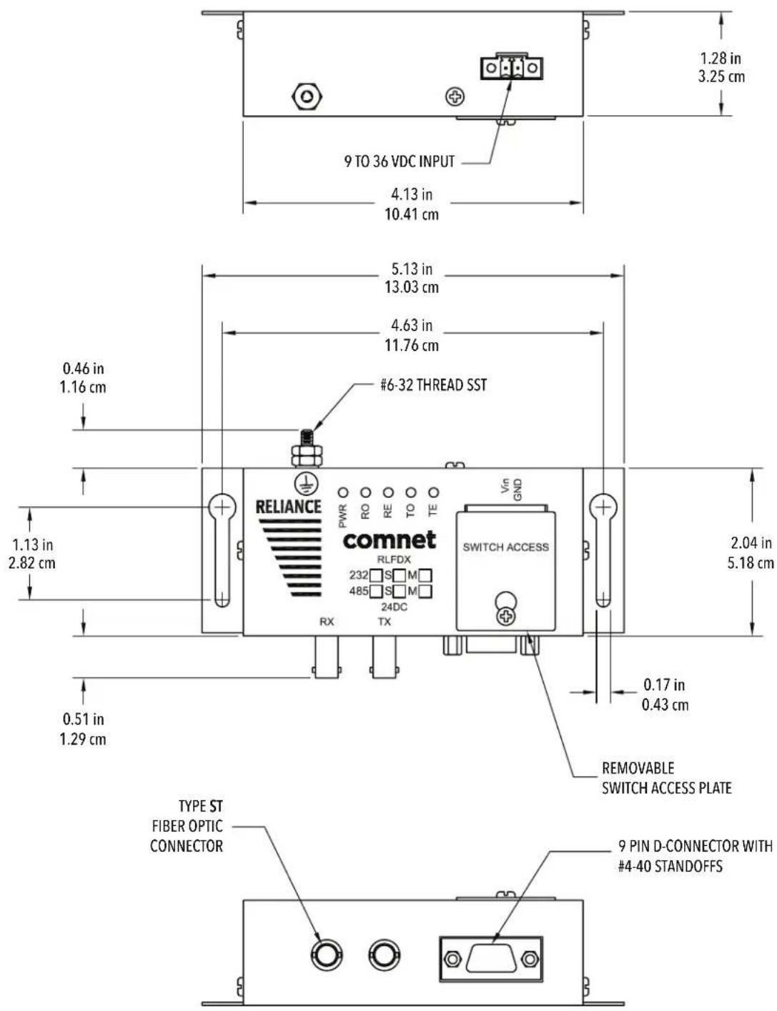
5.2 Outline Configuration & Mechanical Dimensions for Models RLFDX485M2/24DC and RLFDX485S2/24DC
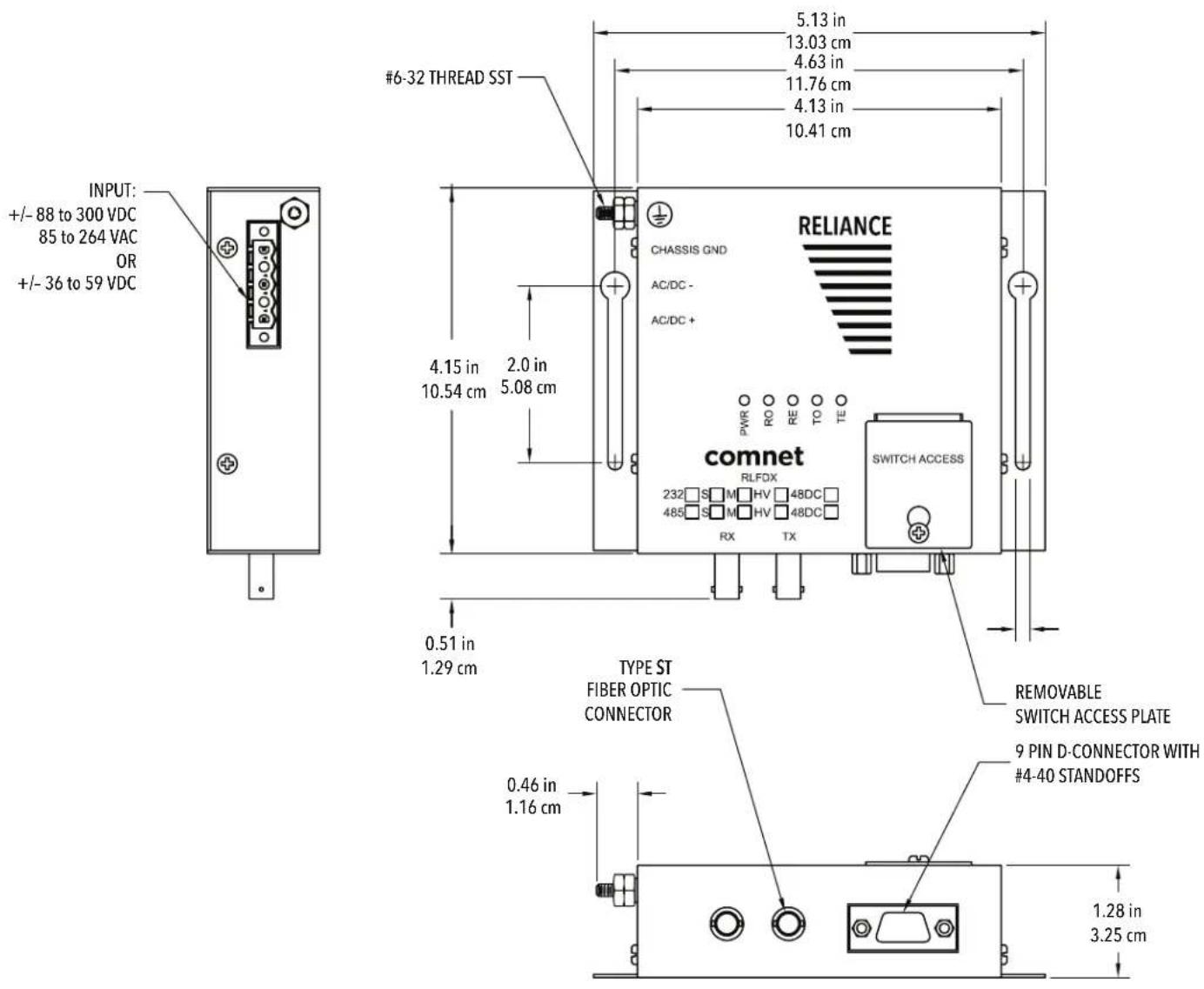
5.3 Outline Configuration & Mechanical Dimensions for Models RLFDX485M2/48DC, RLFDX485S2/48DC, RLFDX485M2/HV, and RLFDX485S2/HV
INSTALLATION AND OPERATION MANUAL RLFDX485 SERIES
ComNet Customer Service
Customer Care is ComNet Technology's global service center, where our professional staff is ready to answer your questions at any time.
Email ComNet Global Service Center: customercare@comnet.net
- INSTALLATION AND OPERATION MANUAL
- RELIANCE
- RLFDX485 Series
- This manual serves the following ComNet Model Numbers:
- Contents
- FCC/CE Regulation 4
- Safety Information 4
- Introduction 7
- Configurations, Operation, and Installation 20
- Applications 31
- Testing And Troubleshooting 38
- Specifications 40
- FCC/CE Regulation
- Warranty
- Disclaimer
- Safety Information
- Warnings, Cautions, and Notes Used in this Publication
- WARNING
- CAUTION
- NOTE / APPLICATION NOTE
- Introduction
- NOTE
- Definitions
- INSTALLATION AND OPERATION MANUAL RLFDX485 SERIES
- Model RLFDX485M2/24DC and RLFDX485S2/24DC Link/Repeaters
- 9 Pin Data Port D-connector
- HD MODE FD MODE
- Switch Settings
- HD / FD Switch
- Repeat Switch
- Logic Inversion Switch
- Input Bias Switch
- Input Data Coupling Switch
- Enable Holdover Switch
- Test Mode Option Switch
- Optical Ports
- Diagnostic LEDs
- Power Connections
- Powering Models RLFDX485M2/24DC & RLFDX485S2/24DC
- Powering Models RLFDX485M2/48DC & RLFDX485S2/48DC
- Powering Models RLFDX485M2/HV and RLFDX485S2/HV
- Peripheral Equipment
- IED
- Fiber Optic Cable (FOC)
- Configurations, Operation, and Installation
- APPLICATION NOTE:
- Point-To-Point Configuration
- Installation
- APPLICATION NOTE
- Installation
- Loop Operation - Peer-To-Peer Configuration
- Installation
- Applications
- Data Rate
- Optical Budget
- Cable Attenuation Factors
- Diameter
- Fittings
- Aging
- Extending the Distance
- Number Of Repeats
- Effects of Data Rate
- Pulse Width Distortion
- Temperature Effect
- Types Of Communication
- Logic Inversion Switch
- Echo Control For 2-Wire RS-485 Local Units In Loop Configurations
- Types Of Communication
- Selection of Fiber Optic Cables (FOC)
- Testing And Troubleshooting
- Testing
- Single-Mode Models RLFDX485S2/24DC, RLFDX485S2/48DC, and RLFDX485S2/HV Only:
- Troubleshooting
- Specifications
- Electrical and Optical Specifications
- Outputs
- Outline Configuration & Mechanical Dimensions for Models RLFDX485M2/48DC, RLFDX485S2/48DC, RLFDX485M2/HV, and RLFDX485S2/HV
- ComNet Customer Service
Brand : ComNet
Model : RLFDX485S2/24DC
Category : Wi-Fi Router