Fusion FCA803 - Wall mount Chief - Free user manual and instructions
Find the device manual for free Fusion FCA803 Chief in PDF.


| Product Type | Accessory Shelf for Flat Panel Mounts |
| Brand | Chief |
| Model | Fusion FCA803 |
| Weight Capacity | 2 lbs (0.9 kg) |
| Extension Range (Below Wall Mount) | 12.0 - 18.3 in (30.5 - 46.5 cm) |
| Extension Range (Above Wall Mount) | 13.0 - 19.0 in (33.0 - 48.3 cm) |
| Mount Compatibility | Chief wall mounts, carts, and ceiling mounts |
| Installation Positions | Above or below display |
| Camera Mount Thread | 1/4-20 |
| Color | Black |
| Material | Steel |
| Included Hardware | Brackets, screws, washers, spacers, hex wrench (1/8") |
| Tools Required (Not Included) | Phillips screwdriver, open-ended wrench |
| Safety | Weight limit must not be exceeded; reduces mount capacity |
| Use | Indoor only |
| Warranty | Standard Chief warranty |
| Part Numbers | FCA803 (small), FCA813 (large) |
| Weight (approx) | 1 lb (0.45 kg) |
| Compliance | Safety warnings per manual |
Frequently Asked Questions - Fusion FCA803 Chief
User questions about Fusion FCA803 Chief
0 question about this device. Answer the ones you know or ask your own.
Ask a new question about this device
Download the instructions for your Wall mount in PDF format for free! Find your manual Fusion FCA803 - Chief and take your electronic device back in hand. On this page are published all the documents necessary for the use of your device. Fusion FCA803 by Chief.
USER MANUAL Fusion FCA803 Chief
INSTALLATION INSTRUCTIONS
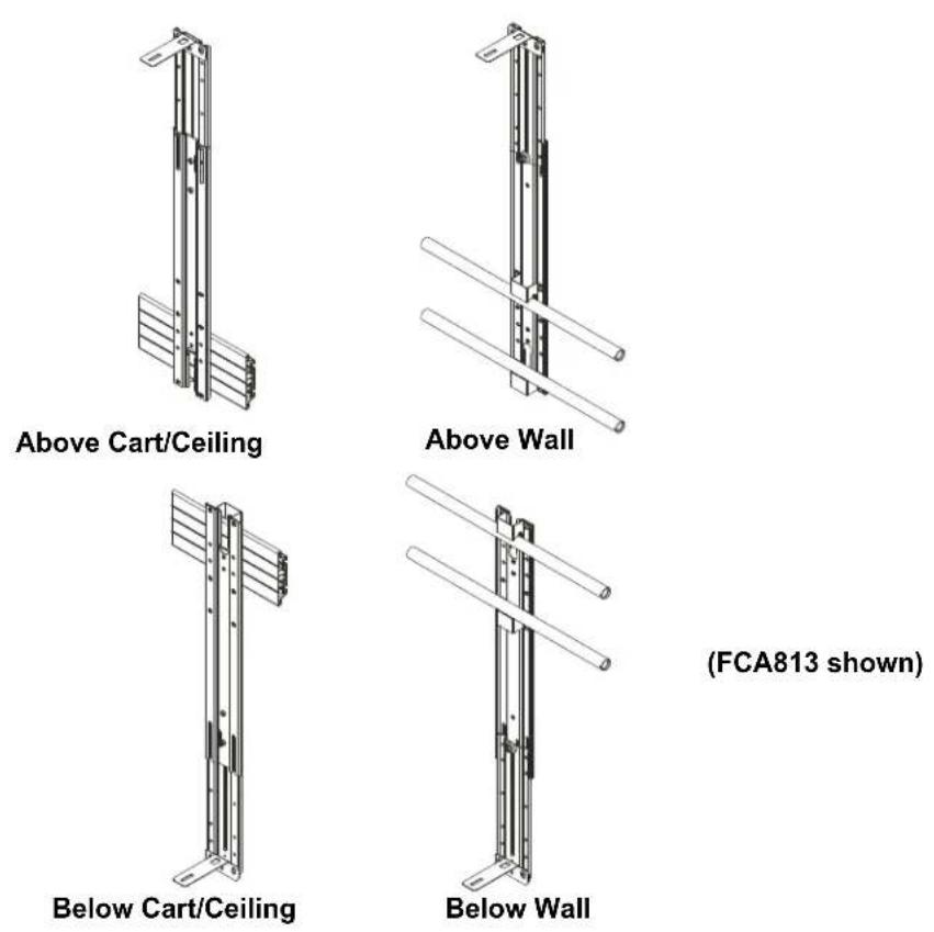
Fusion™ Small Above/Below Accessory Shelf
DISCLAIMER
Milestone AV Technologies and its affiliated corporations and subsidiaries (collectively "Milestone"), intend to make this manual accurate and complete. However, Milestone makes no claim that the information contained herein covers all details, conditions or variations, nor does it provide for every possible contingency in connection with the installation or use of this product. The information contained in this document is subject to change without notice or obligation of any kind. Milestone makes no representation of warranty, expressed or implied, regarding the information contained herein. Milestone assumes no responsibility for accuracy, completeness or sufficiency of the information contained in this document.
Chief® is a registered trademark of Milestone AV Technologies. All rights reserved.
DEFINITIONS
MOUNTING SYSTEM: A MOUNTING SYSTEM is the primary Chief product to which an accessory and/or component is attached.
ACCESSORY: AN ACCESSORY is the secondary Chief product which is attached to a primary Chief product, and may have a component attached or setting on it.
COMPONENT: A COMPONENT is an audiovisual item designed to be attached or resting on an accessory or mounting system such as a video camera, CPU, screen, display, projector, etc.

WARNING: A WARNING alerts you to the possibility of serious injury or death if you do not follow the instructions.

CAUTION: A CAUTION alerts you to the possibility of damage or destruction of equipment if you do not follow the corresponding instructions.

IMPORTANT SAFETY INSTRUCTIONS

WARNING: Failure to read, thoroughly understand, and follow all instructions can result in serious personal injury, damage to equipment, or voiding of factory warranty! It is the installer's responsibility to make sure all accessories are properly assembled and installed using the instructions provided.

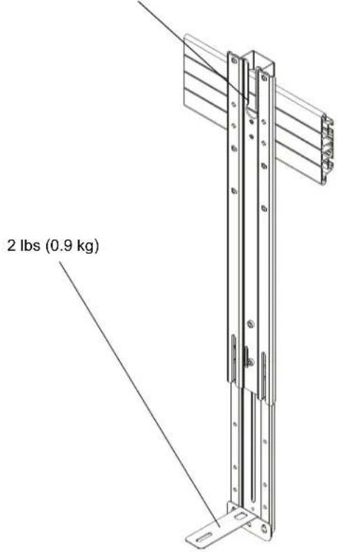
WARNING: Exceeding the weight capacity can result in serious personal injury or damage to equipment! It is the installer's responsibility to make sure the weight mounted to the FCA803/813 shelf does not exceed 2 lbs (0.9 kg).

WARNING: Use of this accessory will decrease the weight capacity of the mounting system to which it is attached by the combined weight of the accessory and all components supported by this accessory! See Figure below for reference.
standard weight limit of mounting system - (weight of FCA803/813 shelf + shelf components)

WARNING: Use this accessory only for its intended use as described in these instructions. Do not use attachments not recommended by the manufacturer.

WARNING: Never operate this accessory if it is damaged. Return the accessory to a service center for examination and repair.

WARNING: Do not use this product outdoors.

WARNING: RISK OF INJURY TO PERSONS! Do not use this accessory to support video equipment such as televisions or computer monitors.
--SAVE THESE INSTRUCTIONS--
DIMENSIONS - FCA803
![FUSION WALL BELOW MOUNT SETUP CENTER OF MOUNT [540.74] 21.29 [438.38] 17.26 12.0-14.3 [304.8-363.2] MIN RANGE 14.3-16.8 [304.8-426.7] INTERMEDIATE RANGE 16.8-18.3 [426.7-464.8] MAX RANGE [104.76] 4.12 FUSION WALL ABOVE MOUNT SETUP [95.25] 3.75 [578.84] 22.79 OVERALL MAX [424.67] 16.72 OVERALL MIN 13.0-15.0 [330.2-381.0] MIN RANGE 15.0-17.5 [381.0-444.5] INTERMEDIATE RANGE 17.5-19.0 [444.5-482.6] MAX RANGE [104.76] 4.12 FUSION CEILING/CART BELOW MOUNT SETUP CENTER OF MOUNT [592.56] 23.33 OVERALL MAX [415.42] 16.36 OVERALL MIN 11.2-13.7 [284.5-348.0] MIN RANGE 13.7-15.6 [348.0-396.2] INTERMEDIATE RANGE 15.6-18.2 [396.2-462.3] MAX RANGE [133.35] 5.25 FUSION CEILING/CART ABOVE MOUNT SETUP [95.25] 3.75 [578.84] 22.79 [403.25] 15.88 12.2-14.2 [309.9-360.7] MIN RANGE 14.2-16.7 [360.7-424.2] INTERMEDIATE RANGE 16.7-19.2 [424.2-487.7] MAX RANGE [133.35] 5.25 CENTER OF MOUNT](/content/2026/06/1203865/images/24daf447d9b8f51d6b574627462cb360f9da06b5742fd42c898f60472757266f.jpg)
DIMENSIONS - FCA813
![FUSION WALL BELOW MOUNT SETUP CENTER OF MOUNT [892.56] 35.14 [670.70] 26.41 19.0 - 21.7 [482.6-551.2] MIN RANGE 21.7 - 26.9 [551.2 - 683.3] INTERMEDIATE RANGE 28.41 26.9 - 28.4 [683.3 - 721.4] MAX RANGE [104.76] 4.12 FUSION WALL ABOVE MOUNT SETUP [878.85] 34.60 [656.99] 25.87 20.6 - 22.3 [523.2 - 566.4] MIN RANGE 22.3 - 27.9 [566.4 - 708.7] INTERMEDIATE RANGE 27.9 - 29.4 [708.7 - 746.8] MAX RANGE [106.17] 4.18 FUSION CEILING/CART BELOW MOUNT SETUP [593.71] 23.37 [464.8 - 508.0] MIN RANGE 18.3 - 20.0 [508.0 - 678.2] INTERMEDIATE RANGE 26.7 - 30.0 [678.2 - 762.0] MAX RANGE [127] 5.00 FUSION CEILING/CART ABOVE MOUNT SETUP [878.85] 34.60 [667.88] 26.29 22.7 - 24.2 [576.6 - 614.7] MIN RANGE 24.2 - 28.0 [614.7 - 711.2] INTERMEDIATE RANGE 28.0 - 31.0 [711.2 - 787.4] MAX RANGE [127] 5.00](/content/2026/06/1203865/images/8cf9e344b722b7f4fa6d717a7c1f51c12ff5e050610ff5e04ff1f65f4c499a44.jpg)
LEGEND
 | Tighten Fastener |  | Phillips Screwdriver |
| Apretar elemento de fijación | Destornillador Phillips | ||
| Befestigungsteil festziehen | Kreuzschlitzschraubendreher | ||
| Apertar fixador | Chave de fendas Phillips | ||
| Serrare il fissaggio | Cacciavite a stella | ||
| Bevestiging vastdraaien | Kruiskopschroevendraaier | ||
| Serrez les fixations | Tournevis à pointe cruciforme | ||
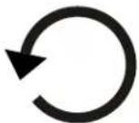 | Loosen Fastener | 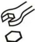 | Open-Ended Wrench |
| Aflojar elemento de fijación | Llave de boca | ||
| Befestigungsteil lösen | Gabelschlüssel | ||
| Desapertar fixador | Chave de bocas | ||
| Allentare il fissaggio | Chiave a punte aperte | ||
| Bevestiging losdraaien | Steeksleutel | ||
| Desserrez les fixations | Clé à fourche | ||
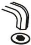 | Hex-Head Wrench | ||
| Llave de cabeza hexagonal | |||
| Sechskantschlüssel | |||
| Chave de cabeça sextavada | |||
| Chiave esagonale | |||
| Zeskantsleutel | |||
| Clé à tête hexagonale |
TOOLS REQUIRED FOR INSTALLATION
 | 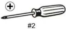 | 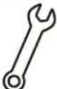 | 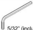 |
| 3/8" | 1/8" (included) |
PARTS
 | ||||||
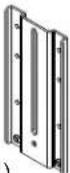 |  |  | E (1) [Center washer] |  | ||
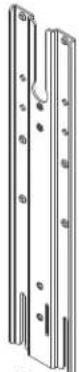
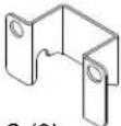
| A (1, [Upright bracket]) | C (2) [Shelf bracket] |  | H (5) 1/4-20 x 1/4" | |||
| F (4) [Large washer] |  | |||||
| J (3) 1/4-20 x 1/2" | M (4) 1/2" |  | ||||
 | ||||||
| K (1) 1/4-20 x 5/8" |  | |||||
| [L (1) 1/4-20 x 3/8" | N (4) 1/4-20 x 7/16" | 1/8" | ||||
| B (1) [Main bracket] * |
ASSEMBLY AND INSTALLATION
Below Installation
NOTE: FCA803 and FCA813 shelves may be installed above or below displays. To install above display, proceed to "Above Installation" Section.
Assembling Shelf to Upright Bracket
- Loosely install two 1/4-20 x 1/2" button head cap screws (J) into lowest holes on upright bracket (A). (See Figure 1) or (See Figure 2)
- Hang shelf support (D) onto two screws installed in Step 1. (See Figure 1) or (See Figure 2)
- Tighten two screws to ensure upright bracket (A) is securely attached to shelf support (D). (See Figure 1) or (See Figure 2)
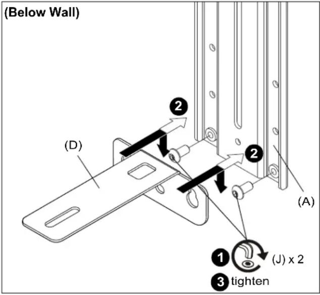
Figure 1
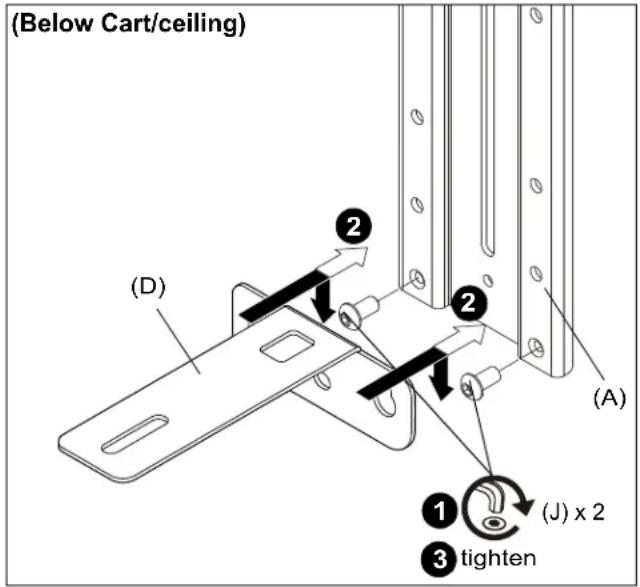
Figure 2
Attaching Shelf to Wall Mount
NOTE: If attaching to cart or ceiling mount, proceed to Attach Shelf to Cart/Ceiling Section.
- Use two 1/4-20 x 1/4" button head cap screws (H) and two large washers (F) to secure shelf bracket (C) to main bracket (B). (See Figure 3)

CAUTION: Slide bracket with caution so that the bracket does not scratch or damage the wall!
- Slide main bracket (B) behind wall mount rails until shelf bracket (C) rests on top of wall mount rail. (See Figure 3)
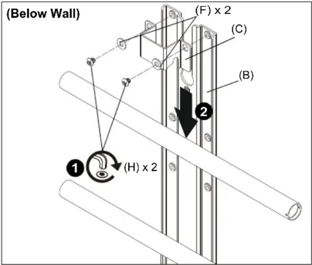
Figure 3
- Slide second shelf bracket (C) underneath lower rail on wall mount, lining up holes on shelf bracket (C) to main bracket (B). (See Figure 4)
- Use two 1/4-20 x 1/4" button head cap screws (H) and two large washers (F) to secure shelf bracket (C) to main bracket (B). (See Figure 4)
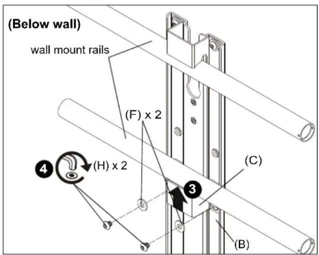
Figure 4
NOTE: Refer to Table 1 and dimension drawings on pages 3-4 to determine the extension level based on extension distance from mount center.
Table 1: Below Wall Mount
| Extension distance from center of mount (in.) | |
| 12.0-14.3 Minimum (FCA803) | |
| 14.3-16.8 Intermediate (FCA803) | |
| 16.8-18.3 Maximum (FCA803) | |
| 19.0-21.7 Minimum (FCA813) | |
| 21.7-26.9 Intermediate (FCA813) | |
| 26.9-28.4 Maximum (FCA813) |
NOTE: Minimum and maximum configurations are shown below. Intermediate configuration is the same.
- Use 1/4-20 x 5/8" hex head flange bolt (K) and center washer (E) to secure upright bracket (A) to main bracket (B). (See Figure 5)
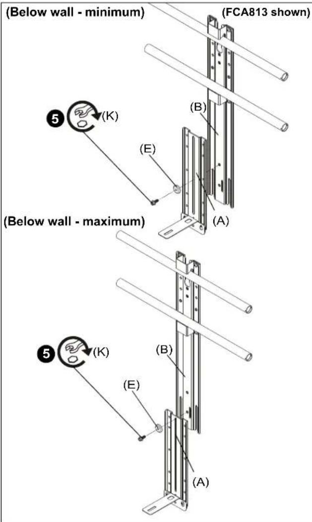
Figure 5
Attaching Shelf to Cart/Ceiling Mount
IMPORTANT ! : If installing to a 2x1 display cart using the FCA623 accessory, proceed to "Installing to FCA623 Accessory" Section (Step 6).
- Use two 1/4-20 x 1/4" button head cap screws (H) and two large washers (F) to secure shelf bracket (C) to main bracket (B). (See Figure 6)
- Slide main bracket (B) onto front of cart/ceiling mount head assembly until shelf bracket (C) rests on top of head assembly. (See Figure 6)
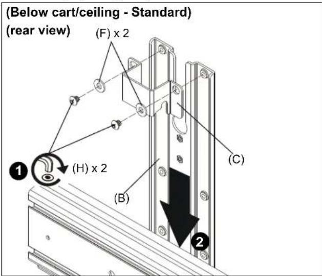
Figure 6
- Slide second shelf bracket (C) underneath head assembly, lining up holes on shelf bracket (C) to holes on main bracket (B). (See Figure 7)
- Use two 1/4-20 x 1/4" button head cap screws (H) and two large washers (F) to secure shelf bracket (C) to main bracket (B). (See Figure 7)
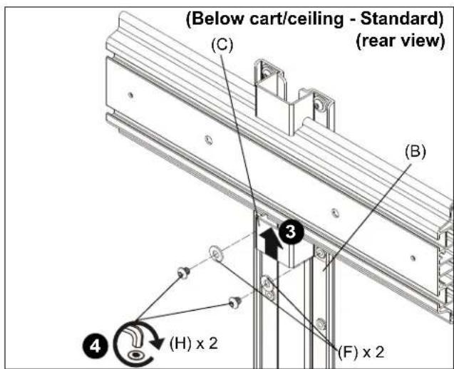
Figure 7
- Proceed to Step 11.
Installing to FCA623 Accessory
IMPORTANT ! : Steps 6-10 only apply if installing to FCA623 accessory.
- Use two 1/4-20 x 7/16" button head cap screws (N), two large washers (F) and two 1/2" spacers (M) to secure shelf bracket (C) to main bracket (B). (See Figure 8)
- Slide main bracket (B) onto front of cart/ceiling mount head assembly until shelf bracket (C) rests on top of head assembly. (See Figure 8)
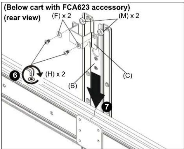
Figure 8
- Slide second shelf bracket (C) underneath head assembly, lining up holes on shelf bracket (C) to holes on main bracket (B). (See Figure 9)
- Slide two 1/2" spacers (M) in between shelf bracket (C) and main bracket (B). (See Figure 9)
- Use two 1/4-20 x 7/16" button head cap screws (N) and two large washers (F) to secure shelf bracket (C) to main bracket (B). (See Figure 9)
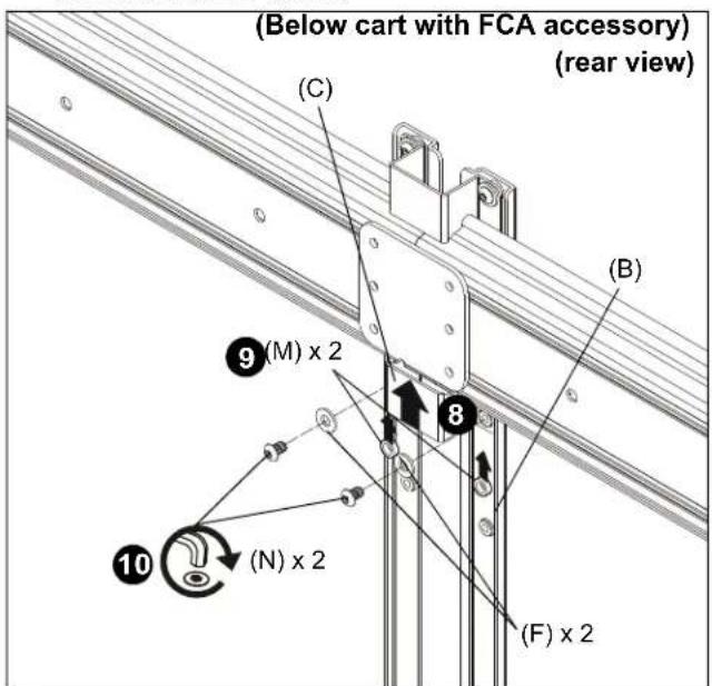
Figure 9
NOTE: Refer to Table 2 and dimension drawings on pages 3-4 to determine the extension level based on extension distance from mount center.
Table 2: Below Cart/Ceiling Mount
| Extension distance from center of mount (in.) | |
| 11.2-13.7 Minimum (FCA803) | |
| 13.7-15.6 Intermediate (FCA803) | |
| 15.6-18.2 Maximum (FCA803) | |
| 18.3-20.0 Minimum (FCA813) | |
| 20.0-26.7 Intermediate (FCA813) | |
| 26.7-30.0 Maximum (FCA813) |
- Use 1/4-20 x 5/8" hex head flange bolt (K) and center washer (E) to secure upright bracket (A) to main bracket (B). (See Figure 10)
NOTE: Maximum configuration is shown below. Several intermediate configurations are possible depending on which holes are used.
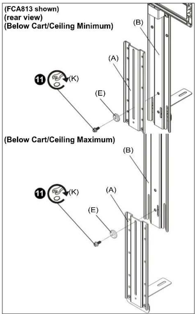
Figure 10
Above Installation
Assembling Shelf to Upright Bracket
-
Install two 1/4-20 x 1/2" button head cap screws (J) into lowest holes on upright bracket (A). (See Figure 11) or (See Figure 12)
-
Hang shelf (E) onto two screws installed in Step 1. (See Figure 11) or (See Figure 12)
-
Secure upright bracket (A) to shelf (E) using:
-
1/4-20 x 1/4" button head cap screw (H) if installing to wall mount. (See Figure 11)
-
1/4-20 x 1/2" button head cap screw (J) if installing to cart/ceiling mount. (See Figure 12)
-
Tighten all three screws to ensure shelf is secure.
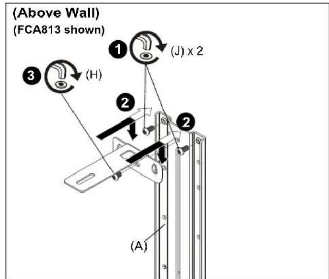
Figure 11
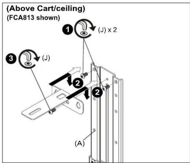
Figure 12
Attaching Shelf to Wall Mount
- Use two 1/4-20 x 1/4" button head cap screws (H) and two large washers (F) to secure shelf bracket (C) to main bracket (B). (See Figure 13)

CAUTION: Slide bracket with caution so that the bracket does not scratch or damage the wall!
- Slide main bracket (B) behind wall mount rails until shelf bracket (C) rests on top wall mount rail. (See Figure 13)
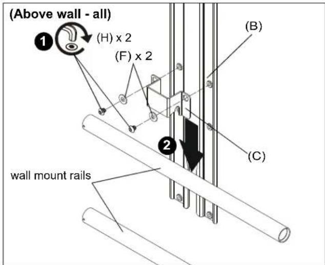
Figure 13
- Slide second shelf bracket (C) underneath lower rail on wall mount, lining up holes on shelf bracket (C) to holes on main bracket (B). (See Figure 14)
- Use two 1/4-20 x 1/4" button head cap screws (H) and two large washers (F) to secure shelf bracket (C) to main bracket (B). (See Figure 14)
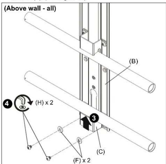
Figure 14
NOTE: Refer to Table 3 and dimension drawings on pages 3-4 to determine the extension level based on extension distance from mount center.
Table 3: Above Wall Mount
| Extension distance from center of mount (in.) | |
| 13.0-15.0 Minimum (FCA803) | |
| 15.0-17.5 Intermediate (FCA803) | |
| 17.5-19.0 Maximum (FCA803) | |
| 20.6-22.3 Minimum (FCA813) | |
| 22.3-27.9 Intermediate (FCA813) | |
| 27.9-29.4 Maximum (FCA813) |
NOTE: Minimum and maximum configurations are shown below. Intermediate configuration is the same.
- Use 1/4-20 x 5/8" hex head flange bolt (K) and center washer (E) to secure upright bracket (A) to main bracket (B). (See Figure 15)
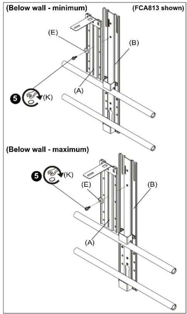
Figure 15
Attaching Shelf to Cart/Ceiling Mount
IMPORTANT ! : If installing to a 2x1 display cart using the FCA623 accessory, proceed to "Installing to FCA623 Accessory" Section (Step 6).
-
Use two 1/4-20 x 1/4" button head cap screws (H) and two large washers (F) to secure shelf bracket (C) to main bracket (B). (See Figure 16)
-
Slide main bracket (B) onto front of cart/ceiling mount head assembly until shelf bracket (C) rests on top of head assembly. (See Figure 16)
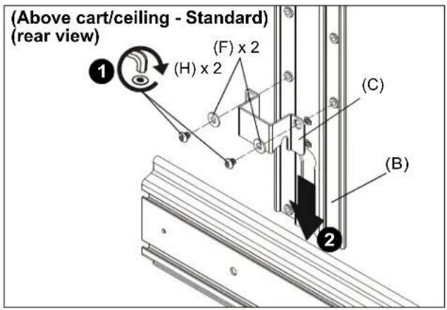
Figure 16
-
Slide second shelf bracket (C) underneath head assembly, lining up holes on shelf bracket (C) to holes on main bracket (B). (See Figure 17)
-
Use two 1/4-20 x 1/4" button head cap screws (H) and two large washers (F) to secure shelf bracket (C) to main bracket (B). (See Figure 17)
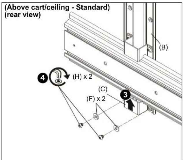
Figure 17
- Proceed to Step 11.
Installing to FCA623 Accessory
NOTE: Steps 6-10 only apply if installing to FCA623 accessory.
- Use two 1/4-20 x 7/16" button head cap screws (N), two large washers (F) and two 1/2" spacers (M) to secure shelf bracket (C) to main bracket (B). (See Figure 18)
- Slide main bracket (B) onto front of cart mount head assembly until shelf bracket (C) rests on top of head assembly. (See Figure 18)
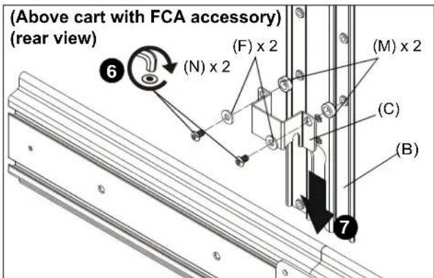
Figure 18
- Slide second shelf bracket (C) underneath head assembly, lining up holes on shelf bracket (C) to holes on main bracket (B). (See Figure 19)
- Slide two 1/2" spacers (M) in between shelf bracket (C) and main bracket (B). (See Figure 19)
- Use two 1/4-20 x 1/2" button head cap screws (J) and two large washers (F) to secure shelf bracket (C) to main bracket (B). (See Figure 19)
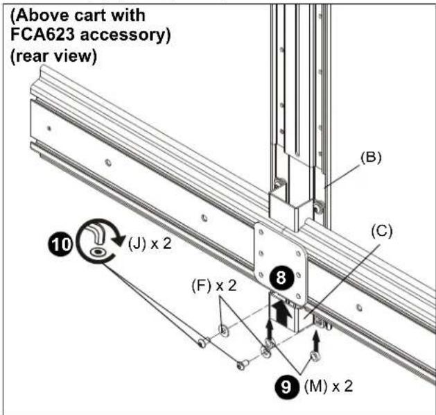
Figure 19
NOTE: Refer to Table 4 and dimension drawings on pages 3-4 to determine the extension level based on extension distance from mount center.
Table 4: Above Cart/Ceiling
| Extension distance from center of mount (in.) | |
| 12.2-14.2 Minimum (FCA803) | |
| 14.2-16.7 Intermediate (FCA803) | |
| 16.7-19.2 Maximum (FCA803) | |
| 22.7-24.2 Minimum (FCA813) | |
| 24.2-28.0 Intermediate (FCA813) | |
| 28.0-31.0 Maximum (FCA813) |
NOTE: Maximum and minimum configurations are shown below. Several intermediate configurations are possible depending on which holes are used.
- Use 1/4-20 x 5/8" hex head flange bolt (K) and center washer (E) to secure upright bracket (A) to main bracket (B). (See Figure 20) or (See Figure 21)
- (For maximum/intermediate extension ONLY) Use two 1/4-20 x 1/2" button head cap screws (J) to secure upright bracket (A) to main bracket (B). (See Figure 20)
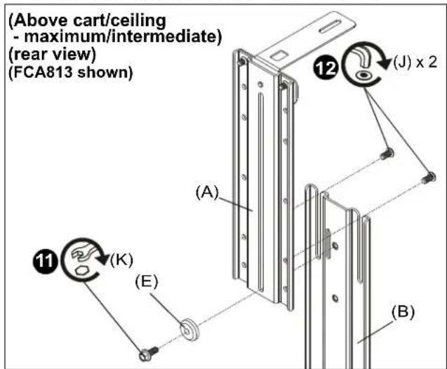
Figure 20
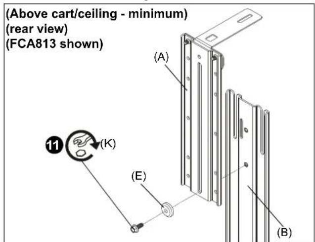
Figure 21
Height Adjustment
- Loosen hardware used to attach main bracket (B) to upright bracket (A). (See Figure 22)
- Adjust shelf height as desired. (See Figure 22)
NOTE: For all above display installations, it is recommended that the shelf be positioned so that it rests on top of display to help ensure an even mount.
- Tighten hardware used to attached main bracket (B) to upright bracket (A). (See Figure 22)
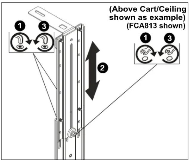
Figure 22
Installing Camera (not included)

WARNING: Exceeding the weight capacity can result in serious personal injury or damage to equipment! It is the installer's responsibility to make sure the combined weight mounted on the FCA803/813 does not exceed 2 lbs (0.9 kg).
NOTE: Screw mounting options will vary based upon camera model.
- Install 1/4-20 x 3/8" Phillips pan machine screw (L) through mounting slot on shelf and into hole on bottom of camera. (See Figure 23)
- Route cable from camera towards back of shelf and down behind the FCA803/813. (See Figure 23)
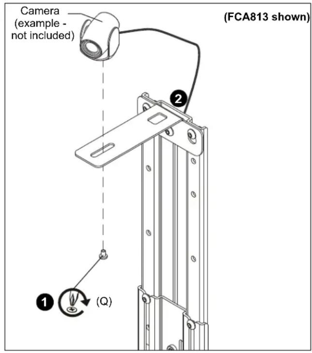
Figure 23

CHIEF®
Our Mounts. Your Vision.
Chief, a products division of Milestone AV Technologies
8800-003090 Rev00
©2018 Milestone AV Technologies
www.milestone.com
10/18
USA/International A 6436 City West Parkway, Eden Prairie, MN 55344
P 800.582.6480 / 952.225.6000
F 877.894.6918 / 952.894.6918
Europe A Franklinstraat 14, 6003 DK Weert, Netherlands
P +31 (0) 495 580 852
F +31 (0) 495 580 845
Asia Pacific A Office No. 918 on 9/F, Shatin Galleria
18-24 Shan Mei Street
Fotan, Shatin, Hong Kong
P 852 2145 4099
F 852 2145 4477

- INSTALLATION INSTRUCTIONS
- Fusion™ Small Above/Below Accessory Shelf
- DISCLAIMER
- DEFINITIONS
- IMPORTANT SAFETY INSTRUCTIONS
- ASSEMBLY AND INSTALLATION
- Below Installation
- Assembling Shelf to Upright Bracket
- Attaching Shelf to Wall Mount
- Attaching Shelf to Cart/Ceiling Mount
- Installing to FCA623 Accessory
- Above Installation
- Height Adjustment
- Installing Camera (not included)
- CHIEF®
Brand : Chief
Model : Fusion FCA803
Category : Wall mount