Pinnacle DPD34D - Security Camera Digimerge - Free user manual and instructions
Find the device manual for free Pinnacle DPD34D Digimerge in PDF.


| Product Type | Security Camera (Indoor Dome Model DPD34D / Vandal Dome Model DPV34D) |
| Brand | Digimerge |
| Image Sensor | 1/3" Sony Ex-View II 960H |
| Total Pixels | 976 (H) x 494 (V) |
| Resolution | 700+ TV Lines |
| Minimum Illumination | 0.00002 Lux (F1.2) with Slow Shutter (x512) |
| Lens | 2.8 - 10.5mm Varifocal F1.4 DC Auto Iris |
| Video Output | 1.0 Vp-p (75 ohm, composite) via BNC and RCA test jack |
| S/N Ratio | More than 50dB (AGC OFF) |
| Power Source | DC 12V or AC 24V ±10% |
| Power Consumption | 2.5W Max |
| Operating Temperature | -10 to 50°C |
| Operating Humidity | 0-90% RH |
| Mounting Options | Surface, Semi-Flush (Indoor only), Junction Box, Wall, Pendant, Corner, Pole (with optional accessories) |
| Weatherproof Rating | IP66 (Vandal Dome DPV34D only) |
| OSD Control | Joystick for menu navigation; includes Exposure, Picture Adjust, White Balance, WDR, DNR, Day/Night, Privacy Masking, Motion Detection |
| Special Features | 3D Digital Noise Reduction (DNR), Advanced Shadow Reduction (D-WDR), Sense-Up, Digital Image Stabilization |
| Package Contents (Indoor Dome) | Camera, locking screws (PA3 type), instruction guide, surface & flush mounting templates, RCA-BNC test cable, junction box plate, mounting screw pack |
| Cleaning Instructions | Use slightly damp soft cloth with mild household detergent. Avoid strong solvents like thinner or benzine. |
| Safety Warnings | Do not expose to rain or moisture; unplug if not in use; use only recommended attachments; refer servicing to qualified personnel. |
Frequently Asked Questions - Pinnacle DPD34D Digimerge
User questions about Pinnacle DPD34D Digimerge
0 question about this device. Answer the ones you know or ask your own.
Ask a new question about this device
Download the instructions for your Security Camera in PDF format for free! Find your manual Pinnacle DPD34D - Digimerge and take your electronic device back in hand. On this page are published all the documents necessary for the use of your device. Pinnacle DPD34D by Digimerge.
USER MANUAL Pinnacle DPD34D Digimerge
natural_image
Technical line drawing of a mechanical component with concentric rings and a central hole (no text or symbols)
natural_image
Technical line drawing of a mechanical component with concentric rings and mounting features (no text or symbols)Vandal Model: DPV34D
Indoor Model: DPD34D
WARNINGS AND CAUTIONS:
TO REDUCE THE RISK OF FIRE OR ELECTRIC SHOCK, DO NOT EXPOSE THIS PRODUCT TO RAIN OR MOISTURE. DO NOT INSERT ANY METALLIC OBJECTS THROUGH THE VENTILATION GRILLS OR OTHER OPENINGS ON THE EQUIPMENT.
CAUTION:

CAUTION
RISK OF ELECTRIC SHOCK DO NOT OPEN

CAUTION: TO REDUCE THE RISK OF ELECTRIC SHOCK, DO NOT REMOVE COVER(OR BACK). NO USER-SERVICEABLE PARTS INSIDE. REFER SERVICING TO QUALIFIED SERVICE PERSONNEL.
EXPLANATION OF GRAPHICAL SYMBOLS

The lightning flash with arrowhead symbol, within an equilateral triangle, is intended to alert the user to the presence of uninsulated "dangerous voltage" within the product's enclosure that may be of sufficient magnitude to constitute a risk of electric shock to persons.

The exclamation point within an equilateral triangle is intended to alert the user to the presence of important operating and maintenance (servicing) instructions in the literature accompanying the product.
PRECAUTIONS
Safety
Should any liquid or solid object fall into the cabinet, unplug the unit and have it checked by the qualified personnel before operating it any further.
Unplug the unit from the wall outlet if it is not going to be used for several days or more. To disconnect the cord, pull it out by the plug. Never pull the cord itself.
Allow adequate air circulation to prevent internal heat build-up. Do not place the unit on surfaces (rugs, blankets, etc.) or near materials(curtains, draperies) that may block the ventilation holes.
Installation
Do not install the unit in an extremely hot or humid place or in a place subject to excessive dust, mechanical vibration.
The unit is not designed for submersion in water.
Cleaning
Clean the unit with a slightly damp soft cloth. Use a mild household detergent. Never use strong solvents such as thinner or benzine as they might damage the finish of the unit.
Retain the original carton and packing materials for safe transport of this unit in the future.
FCC COMPLIANCE STATEMENT
FCC INFORMATION : THIS EQUIPMENT HAS BEEN TESTED AND FOUND TO COMPLY WITH THE LIMITS FOR A CLASS A DIGITAL DEVICE, PURSUANT TO PART 15 OF THE FCC RULES. THESE LIMITS ARE DESIGNED TO PROVIDE REASONABLE PROTECTION AGAINST HARMFUL INTERFERENCE WHEN THE EQUIPMENT IS OPERATED IN A COMMERCIAL ENVIRONMENT. THIS EQUIPMENT GENERATES, USES, AND CAN RADIATE RADIO FREQUENCY ENERGY AND IF NOT INSTALLED AND USED IN ACCORDANCE WITH THE INSTRUCTION MANUAL, MAY CAUSE HARMFUL INTERFERENCE TO RADIO COMMUNICATIONS. OPERATION OF THIS EQUIPMENT IN A RESIDENTIAL AREA IS LIKELY TO CAUSE HARMFUL INTERFERENCE IN WHICH CASE THE USER WILL BE REQUIRED TO CORRECT THE INTERFERENCE AT HIS OWN EXPENSE.
CAUTION : CHANGES OR MODIFICATIONS NOT EXPRESSLY APPROVED BY THE PARTY RESPONSIBLE FOR COMPLIANCE COULD VOID THE USER'S AUTHORITY TO OPERATE THE EQUIPMENT.
THIS CLASS A DIGITAL APPARATUS COMPLIES WITH CANADIAN ICES-003. CET APPAREIL NUMÉRIQUE DE LA CLASSE A EST CONFORME À LA NORME NMB-003 DU CANADA.
CE COMPLIANCE STATEMENT
WARNING
This is a Class A product. In a domestic environment this product may cause radio interference in which case the user may be required to take adequate measures.
1. READ AND RETAIN INSTRUCTIONS
Read the instruction manual before operating the equipment. Retain the manual for future reference.
2. CLEANING
Turn the unit off and unplug from the power outlet before cleaning. Use a damp cloth for cleaning. Do not use harsh cleansers or aerosol cleaners.
3. ATTACHMENTS
Do not use attachments unless recommended by the manufacturer as they may affect the functionality of the unit and result in the risk of fire, electric shock or injury.
4. MOISTURE
Do not use equipment near water or other liquids.
5. ACCESSORIES
Equipment should be installed in a safe, stable location. Any wall or shelf mounting accessory equipment should be installed using the manufacturer's Instructions. Care should be used when moving heavy equipment. Quick stops, excessive force, and uneven surfaces may cause the equipment to fall causing serious injury to persons and objects.
6. VENTILATION
Openings in the equipment, if any, are provided for ventilation to ensure reliable operation of the unit and to protect if from overheating. These openings must not be blocked or covered
7. POWER SOURCES
The equipment should be operated only from the type of power source indicated on the marking label. If you are not sure of the type of power supplied at the installation location, contact your dealer. For equipment designed to operate from battery power, refer to the operating instructions.
8. GROUNDING OR POLARIZATION
Equipment that is powered through a polarized plug (a plug with one blade wider than the other) will fit into the power outlet only one way. This is a safety feature. If you are unable to insert the plug fully into the outlet, try reversing the plug. Do not defeat the safety purpose of the polarized plug.
Alternate Warning: If the equipment is powered through a three-way grounding-type plug, a plug having a third (grounding) pin, the plug will only fit into a grounding-type power outlet. This is a safety feature. Do not defeat the safety purpose of the grounding-type plug. If your outlet does not have the grounding plug receptacle, contact your local electrician.
9. CORD AND CABLE PROTECTION
Route power cords and cables in a manner to protect them from damage by being walked on or pinched by items places upon or against them.
10. LIGHTNING
For protection of the equipment during a lightning storm or when it is left unattended and unused for long periods of time, unplug the unit from the wall outlet. Disconnect any antennas or cable systems
that may be connected to the equipment.
This will prevent damage to the equipment due to Lightning or power-line surges.
11. OVERLOADING
Do not overload wall outlets and extension cords as this can result in a risk of fire or electric shock.
12. SERVICING
Do not attempt to service the video monitor or equipment yourself as opening or removing covers may expose you to dangerous voltage or other hazards. Refer all servicing to qualified service personnel.
13. DAMAGE REQUIRING SERVICE
Unplug the equipment from the wall outlet and refer servicing to qualified service personnel under the Following conditions:
A. When the power supply cord or the plug has been damaged.
B. If liquid has spilled or objects have fallen into the Unit.
C. If the equipment has been exposed to water or other liquids.
D. If the equipment does not operate normally by following the operating instructions, adjust only those controls that are covered by the operating instructions. Improper adjustment of other controls may result in damage to the unit.
E. If the equipment has been dropped or the casing Damaged.
F. When the equipment exhibits a distinct change in performance.
14. REPLACEMENT PARTS
When replacement parts are required, be sure the service technician uses replacement parts specified by the manufacturer or that have the same characteristics as the original part.
Unauthorized substitutions may result in fire, electric shock, or other hazards.
15. SAFETY CHECK
Upon completion of any service or repairs to the equipment, ask the service technician to perform safety checks to verify that the equipment is in proper operating condition.
16. FIELD INSTALLATION
The installation of equipment should be made by a qualified service person and should conform to all local codes.
- CAUTION-these servicing instructions are for use by qualified service personnel only. to reduce the risk of electric shock do not perform any servicing other than that contained in the operating instructions unless you are qualified to do so.
17-1 Regulated Class 2 power source only.
17-2 Do NOT use power source other than that specified.
All Models Feature:
• 1/3" Sony Ex-View™ II 960H
• 2.8-10.5mm Varifocal Day/Night Lens F1.4 DC Iris
• Excellent low light performance using Polaris Vision3
• 0.03Lux/F1.2 (Color)
• 0.00002Lux w/Sense-Up at x512
• 700+ TV lines of resolution
• 3D Digital Noise Reduction (3D-DNR)
• Advanced Shadow Reduction (D-WDR)
- OSD menu control
• Privacy Masking / Motion Detection
• VIDEO OUT(BNC)
• Operates in 12VDC or 24VAC
• Test Monitor Output (RCA)
DPD34D
- Indoor Dome Model
• Camera Mounting: Surface / Semi-Flush mounting
DPV34D
• Vandal Dome Model
• Camera Mounting: Surface Mounting
• Weatherproof Rated (IP66)
SPECIFICATIONS
| GeneralDPD34DDPV34D | |
| Power source DC 12V / AC 24V +10% | |
| Power consumption 2.5Watt Max | |
| Minimum Power Requirement | 191mA DC / 150mA AC |
| Image sensor 1/3" Sony Ex-ViewTM II 960H | |
| Total pixels 976 (H) x 494 (V) | |
| Scanning system 2:1 interlace | |
| Scanning frequency 15.734KHz(H), 59.95Hz(V) | |
| Sync.system Internal / Line Lock | |
| Resolution 700+ TV Lines | |
| Min.illumination 0.00002 LUX (F1.2) Slow Shutter (x512) | |
| Video output 1.0 Vp-p (75 ohm, composite) | |
| S/N Ratio more than 50dB (AGC OFF) | |
| Power input | 2-Pin terminal block (Detachable) |
| Video output | BNC Connector (2nd video RCA) |
| Lens mount Fixed mount | |
| Lens | 2.8 - 10.5mm F1.4 Varifocal DC Auto iris |
| Operating temperature | -10~50°C |
| Operating humidity | 0-90% RH |

Vandal Dome Dimensions

Indoor Dome Dimensions

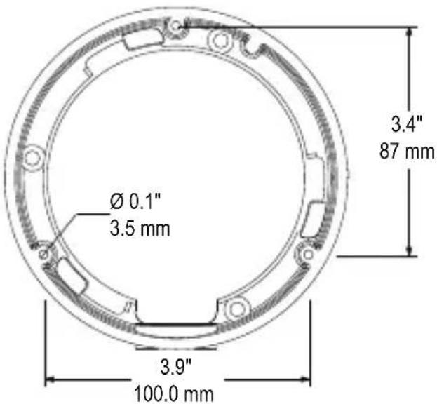
Base hole positions
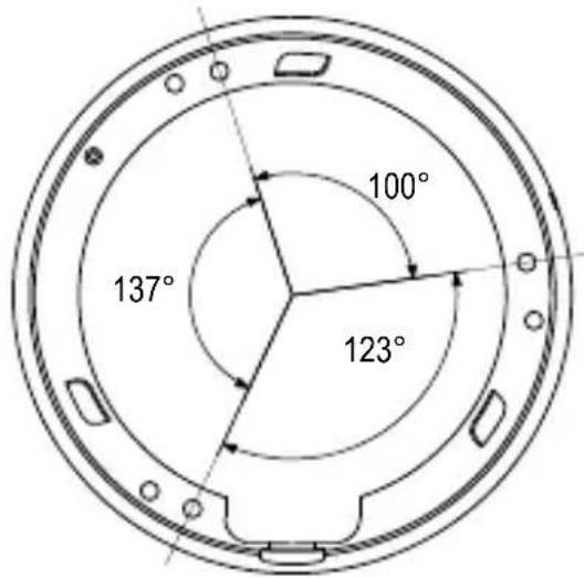
Underside Base hole positions

Recess cutout and fitting clearance. Recess Mount Fittin
Indoor Dome package contains the following:
Camera in housing ----1
Camera Locking screws (PA3 Type)----2
Instruction guide (This Document)----1
Surface & Flush Mounting Templates----2
RCA - BNC test cable----1
Junction Box Plate----1
Mounting screw pack ----1
Vandal Dome package contains the following:
Camera in housing ----1
Camera Locking screws (PM4 Type) ----3
Instruction guide (This Document)----1
Surface Mounting Template ----1
RCA - BNC test cable----1
Junction Box Plate----1
Mounting screw pack ----1
Tamper allen key----1
Conduit Key 1
JUNCTION BOX PLATE
Junction box plate allows fitting of either Vandal dome or Indoor dome to standard 2S, 4S and Octagon junction boxes.
Junction Box fitting plate accessories:
Junction Box Fiting plate ----1
2S / 4S plate screws (KM3.5 Type) ----4
Octagon fitting screws (KM4 Type)----2
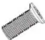
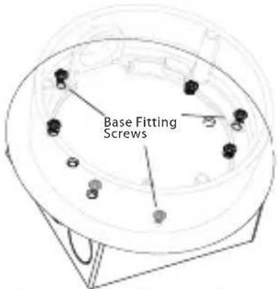
Base Fitting Screws PWM3 ----3

Locking Screw
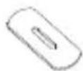
Conduit Key

Allen Key

natural_image
Illustration of multiple screw fasteners with different end caps (no text or symbols)Mounting Screws Pack.
3pc 70mm / 2.8in Screws
3pc 30mm / 1.2in Screws
3pc 40mm 1.6in plugs
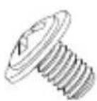
Base Fitting Screw.

Octagon Screw
2S / 4S
Screw

natural_image
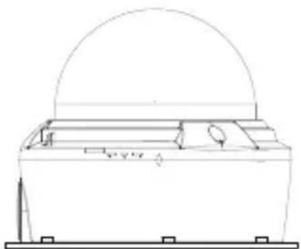
Technical line drawing of a mechanical assembly with a dome-shaped top and internal components (no text or symbols)Screw hole overview Camera base fitting illustration Junction box fitting plate attached to camera

2S FITTING
a. 2S Fitting requires only 2pcs of 2S/4S screws.
Note: You have a reduced space in which to hide cables using this type of installation. Recommended for indoor dome only.

4S FITTING
a. 4S Fitting requires 2pcs of 2S/4S screws.
Note: Suitable for both indoor and vandal domes.

flowchart
graph TD
    A["Screws"] --> B["Cable Entry"]
    A --> C["Node 1"]
    A --> D["Node 2"]
    A --> E["Node 3"]
    A --> F["Node 4"]
    A --> G["Node 5"]
    A --> H["Node 6"]
    A --> I["Node 7"]
    A --> J["Node 8"]
TWO GANG FITTING
a. Two gang fitting (switch box) requires 4pcs of 2S/4S screws.
Note: A two gang provides the most robust fitting. Suitable for both indoor and vandal domes.

flowchart
graph TD
    A["Screws"] --> B["Cable Entry"]
    style A fill:#f9f,stroke:#333
    style B fill:#ccf,stroke:#333
OCTAGON FITTING
a. 4" Octagon fitting requires only 2pcs of Octagon screws.
Note: Screws used for the octagon fitting are larger compared to those used for the 2S/4S (M4 type). Suitable for both indoor and vandal domes

natural_image
Simple line drawing of a lamp with a handle and base (no text or symbols)Wall Mount - model # MNTV2XW

natural_image
Technical line drawing of a mechanical component with a flanged base and circular housing (no text or symbols)Pendant Mount - model # MNTV2XC

natural_image
Technical line drawing of a square mechanical component with mounting holes and internal slots (no text or symbols)Junction Box Mount - model # MNTV2XB

natural_image
Technical line drawing of two mechanical components, one cylindrical and one flanged, with no visible text or symbols.Pendant Cap - model # MNTV2XPC
Replaces the need for the camera base. Compatible with ceiling conduit installations.
Mount for either Vandal or Indoor Dome. Can also mount MNTV2XC or MNTV2XW.

natural_image
Technical line drawing of a mechanical bracket with mounting holes and a central circular cutout (no text or symbols)Corner Mount bracket - model # MNTV2XR

natural_image
Technical line drawing of a mechanical assembly with circular components and a rectangular base (no text or symbols)Pole Mount - model # MNTV2XP
Can fit either MNTV2XW or MNTV2XJ.
Can fit either MNTV2XW or MNTV2XJ.

natural_image
Technical line drawing of a mechanical housing or enclosure with mounting flanges and internal components (no text or symbols)Junction Box Attachment for
MNTV2XW & MNTV2XC - model # MNTV2XJ
Fits either wall mount and ceiling mount.
Symmetrical design - reversible for top or bottom conduit.
INSTALLATION. VANDAL DOME
3

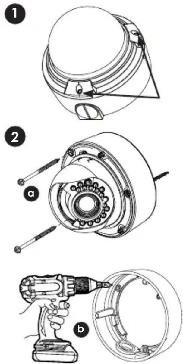
1) Loosen the three tamper screws using the provided allen key. Lift the dome cover.
Note: If you plan to use conduit fitting, remove conduit cap using the provided conduit key.

natural_image
Three simple line drawings of mechanical parts or tools, no text or symbols presentMounting Template Conduit Key Allen Key
Method 1 - Direct Attach Install
2a) Use the included mounting template (Installation Option 2) to mark and pre-drill the required holes. Remove 2 of the 3 base locking screws. Use 2pc of the 2.8" screws to mount the camera directly to the mounting surface.
Remove the 3rd base locking screw and install the 3rd 2.8" screw.
Go to step 4
OR
Method 2 - Camera Base Install
2b) Use the included mounting template (Installation Option 1) to mark and pre-drill the required holes. Remove the camera base by unscrewing the 3 base locking screws, and turn camera module approx. 5 degrees counter-clockwise to detach camera base from the camera module. Install the base to the correct holes as indicated on the mount template using the 1.2" screws. Go to step 3a.
Method 3 - Junction Box Install
2c) Attach provided fitting plate to junction box (see page 4 for details). Remove the camera base by unscrewing the 3 base locking screws, and turn the camera module approx. 5 degrees counterclockwise to detach camera base from camera module. Install the base to the junction box using the base attachment screws. Go to step 3a.
3a) Reinsert camera module into camera base by aligning the arrow notches on the edge of the camera module and the camera base (label on edge of camera module indicates the location of the arrow notch), and turning camera module clockwise to lock into place.
3b) Use the 3 base locking screws to secure camera base to camera module.
Go to step 4 on page 7 to complete installation.
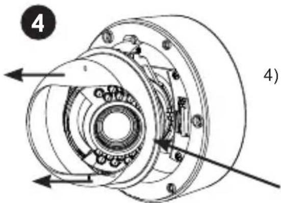
4) Remove camera cover by squeezing the back and front of the cover (as indicated by the arrow indicators) at the same time and lifting it up and away from the lens.
Arrow

5) Insert the included video test cable into the RCA jack and connect to a test monitor to set up camera.
Video test cable
RCA Jack


6a) Adjust camera viewing angle and secure into place by tightening thumb screw using a flat head screwdriver.
Note: Lens adjustment levers are by default in the locked position. Turn counter clockwise to unlock. Tighten levers to secure lens setting.
6b) Adjust lens and OSD as required.
6c) Re-attach the camera cover, using the thumb screw as a guide, until it snaps into place.
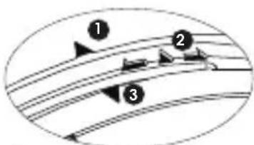
7a) Re-attach the dome cover. Align arrows according to the diagram below to ensure a weatherproof seal.

flowchart
graph TD
    A["1"] --> B["2"]
    B --> C["3"]
1 Arrow on camera base
2 Arrow on camera module (inside camera)
3 Arrow on dome cover.
Correct arrow alignment
7b) Use the allen key to tighten the tamper screws.
Note: Make sure dome cover cord does not get caught in the rubber seal.
INSTALLATION. INDOOR DOME (Surface Fitting)


natural_image
Illustration of a hand using a drill pen to adjust a circular mechanical component (no text or symbols present)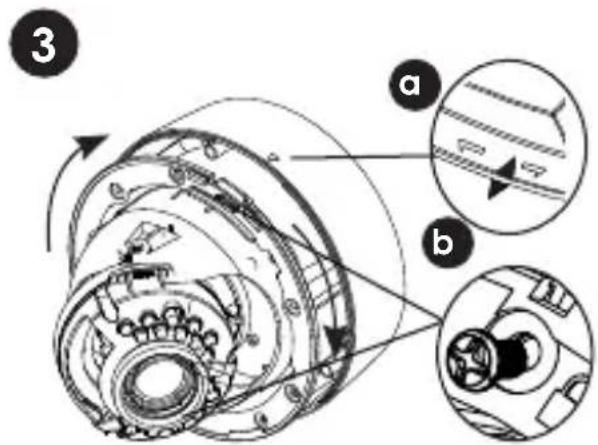
1a) Press down on the tab marked with an arrow to lift up the dome cover slightly
1b) While pressing on tab, twist the dome cover counter clockwise just a few degrees to release dome cover from back clips.
Lift off the cover.
Method 1 - Direct Attach Install
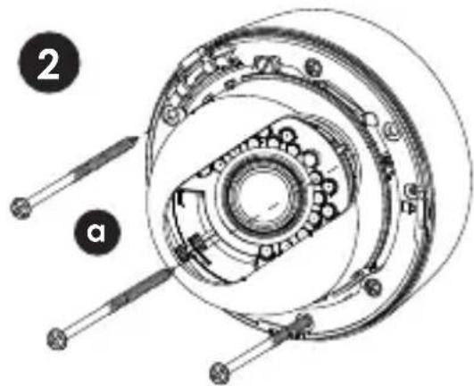
2a) Use included mounting template to mark and pre-drill the required holes. Use included 2.8" screws to mount the camera directly to the mounting surface.
Go to step 3 on page 9 to complete installation.
OR
Method 2 - Camera Base Install
2b) Use the included mounting template (Installation Option 1) to mark and pre-drill the required holes. Remove the camera base by unscrewing the base locking screws (indicated by padlock markings) and turn camera module approx. 5 degrees counterclockwise to detach camera base from the camera module. Install the base as indicated using the 1.2" screws. Go to step 3a.
Method 3 - Junction Box Install
2c) Attach provided fitting plate to junction box (see page 4 for details). Remove the camera base by unscrewing the 3 base locking screws, and turn the camera module approx. 5 degrees counterclockwise to detach camera base from camera module. Install the base to the junction box using the base attachment screws. Go to step 3a.
3a) Reinsert camera module into camera base by aligning the arrow notches, and turning camera module clockwise to lock into place.
3b) Reinstall the base locking screws. (indicated by padlock markings)
Go to step 3 on page 9 to complete installation.
INSTALLATION. INDOOR DOME (Semi-Flush Fitting)
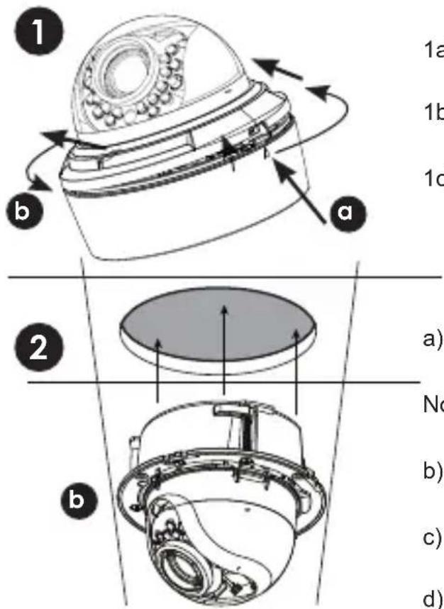
1a) Press down on the tab marked with an arrow to lift up the dome cover slightly
1b) While pressing on tab, twist the dome cover counterclockwise to release dome cover
1c) Remove the camera base by unscrewing the base locking screws (indicated by a padlock markings) and turn camera module approx. 5 degrees counterclockwise to detach camera base from the camera module.
a) Cut semi flush mounting hole into surface using provided Semi-flush Mount Cut-out Template.
Note: Always cut using the inside line of the cutout template
b) Insert camera into cutout. Make sure that the mounting arms are not extended.
c) Turn screwdriver clockwise to unlock all of the 3 mounting arms.
d) Continue turning clockwise to move mounting arms down until they make contact with inner mounting surface.
Note: Once mounting arms have made contact with the inner mounting surface, do not apply too much pressure to avoid damaging surface.

natural_image
Two circular diagrams labeled c and d showing mechanical components with arrows indicating motion or movement (no text or symbols present)
Thumb Screw
a) Remove camera cover by squeezing the back and front of the cover as indicated by the arrow indicators at the same time and lifting it up and away from the lens.
b) Insert the included video test cable into the RCA jack and connect to a test monitor to set up camera. (see page 10).
c) Adjust camera viewing angle and secure into place by tightening thumb screw using a flat head screwdriver. Adjust lens and OSD as required.
Note: Lens adjustment levers are by default in the locked position. Turn counter clockwise to unlock. Tighten levers to secure lens setting.
4
a) Re-attach the camera cover, using the thumb screw as a guide, until it snaps into place.
b) Reattach dome cover.
natural_image
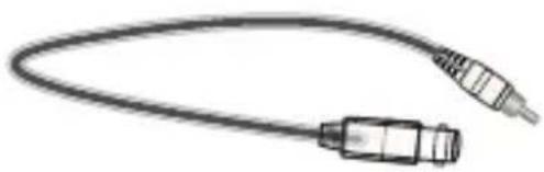
Illustration of a coaxial cable with two connectors (no text or symbols)RCA Service Connector Use supplied RCA - BNC cable If you require BNC output.
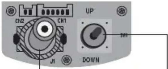
OSD function joystick. Pressing down on joystick acts as ENTER function.
MENU TREE SUMMARY
EXPOSURE · AUTO←
• HIGHLUMINANCE • MODE • BRIGHTNESS • LOWLUMINANCE • MODE
- DSSMAX .AGC MAX
- MANUAL
• MODE • SHUT • AGC
PIC ADJUST • MIRROR • DIS • EZOOM ← • LEVEL • SHARPNESS • HUE • B-GAIN • R-GAIN
• ZOOM • PAN • TILT
WHITE BAL •ATW←
- SPEED • DELAY CNT • ATW FRAME • ENVIRONMENT
- PUSH • USER1/USER2
←·ANTICR · PUSHLOCK
• B-GAIN • R-GAIN
WDR MODE • LEVEL • HLC • CLIPLEVEL • SCALE • BLC
DNR DNR MODE • LEVEL
DAYAUNIGHT
*LL (Line Lock) sub-menu is only shown when the camera is connected to AC power.
OSD MENU control
Press down on the function joystick to access the setup menu. Joystick has 4 directional buttons. Press down on the middle of the joystick to select menu options.
- Main setup menu is displayed on the monitor screen.
SETUP MENU

Select functions by moving the joystick up and down. Move the joystick left and right to change setting values. Press on joystick to confirm selection. If a menu option features a ←, a sub menu is available which can be accessed by pressing down on the joystick.
Once you have finished updating settings, highlight SAVE ALL and press down on the joystick. Then, highlight EXIT and press down on the joystick. If you do not select SAVE ALL, settings changes will be lost when the camera is rebooted.
EXPOSURE

Changes the output exposure settings a choice of AUTO(default) or MANUAL.
AUTO
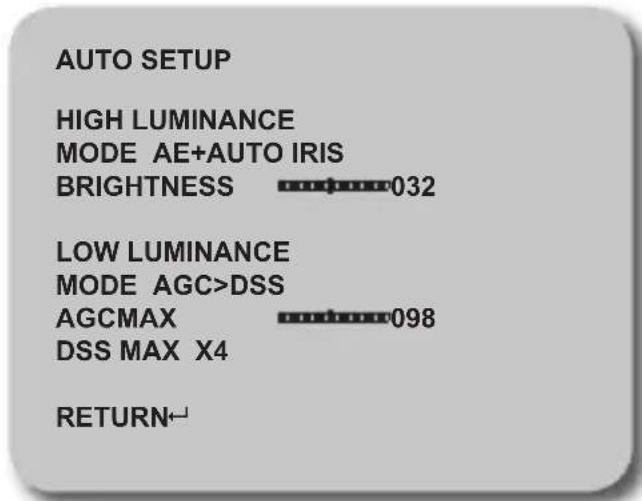
HIGH LUMINANCE
MODE: AE+AUTO IRIS / ME+AUTO IRIS
BRIGHTNESS: 000-255
Brightness level of operating mode as set above.
Default setting is 128
LOW LUMINANCE
MODE: AGC/ SLOW / AGC-DSS / AGC-DSS-AGC / OFF
Settings available only when using DC lens.
AGCMAX: 000-255
Brightness level of operating mode as set above.
Default setting is 098
DSS MAX: X1-512
MANUAL SETUP
MODE SHUT
SHUT 1/60 (S)
AGC 6 (DB)
RETURN←
- MANUAL
MODE: SHUT / SLOW
Lets you select combination of exposure modes.
SHUT: When MODE is set to SHUT, select shutter speed in x / second
1/60, 1/100, 1/250, 1/500, 1/1000, 1/2000,
1/4000,1/10000
Default setting is 1/60
SHUT: When MODE is set to DSS
The shut speed can be 2,4,8,16,32,64,128,256
Default setting is 2
AGC: Set a fixed gain value for the AGC db
6,12,18,24,30,36,42,44.8
PICT ADJUST

Picture and display control settings

• MIRROR: OFF/V-FLIP/H-FLIP/HV-FLIP
Horizontally and vertically flip the display output.
• DIS: ON / OFF Enable/Disable Digital Image Stabilization.
- EZOOM

ZOOM: 000-255 Default 0
PAN: 000-1023 Default 512
TILT: 000-512 Default 256
Note: Zoom must be higher than 0 to use Pan and Tilt settings.
• LEVEL: 000-063 Screen brightness.
• SHARPNESS: 000-015 Screen sharpness.
• HUE: 000-100 Adjust the HUE value
• R-GAIN: 000-255 Adjust the RED gain.
• B-GAIN: 000-255 Adjust the BLUE gain.
WHITE BAL

White Balance can be set to following: ATW / PUSH / USER1 / USER2 / ANTI CR / PUSH LOCK
• ATW (Auto Trace White Balance)

SPEED: 000-255 Specifies the AE control for ATW Default setting is 239
DELAY CNT: 000-255 Sets the time based of ATW change. Default setting is 16
ATW FRAME: x0.50 / x1.00 / x1.50 / x2.00
Sets pull in frame for magnification
Default setting is X0.50
ENVIRONMENT: INDOOR / OUTDOOR
Set the pull in frame of ATW
Default setting is OUTDOOR
- PUSH Use white balance regardless of the subject conditions.
• USER1/2 User defined Blue and Red gain adjustment

other
| User | Value | | :--- | :--- | | USER1 WB | 029 | | B-GAIN | 034 | | R-GAIN | 045 | | RETURN | RETURN |B-GAIN: 000-255 B Gain adjustment for WB
R-GAIN: 000-255 R Gain adjustment for WB
• ANTI CR Activates color rolling suppression.
- PUSH LOCK Press down on joystick to set current scene as the white balance level. Place a 18% gray card in front of the lens and select PUSH LOCK for a natural white level.
WDR
SETUP MENU
EXPOSURE AUTO
PICT ADJUST
WHITE BAL ATW
WDR
DNR
DAY/NIGHT AUTO
Wide Dynamic Range.
WDR SETUP
MODE OFF
LEVEL -
HLC OFF
CLIP LEVEL
SCALE
BLC OFF


RETURN←
• MODE: OFF / D-WDR
E: OFF / D-WDR
D-WDR: Gamma curve, high & low luminance adjusted Default is Off
HLC: OFF / ON / AUTO Highlight compensation.
CLIP LEVEL: 000-255 Clipping level. Default setting is 0
SCALE: 000-015
BLC: OFF / ON BLC can be enabled with WDR OFF only
DNR
SETUP MENU
EXPOSURE AUTO
PICT ADJUST
WHITE BAL ATW
WDR
UNR
DAY/NIGHT AUTO
Digital Noise Reduction.
This function reduces the background noise in a low luminance environment.

• DNR MODE: 2D+3D / 3D / 2D / OFF
Noise reduction Filter mode.
Adjustment of the filter strength.
Default setting is LOW
Day/Night mode can be set to the following options: COLOR/AUTO/EXT/BW. Select COLOR for a color image or BW for black and white. EXT allows the use of an external trigger to activate day/night operation. Use AUTO to have the camera automatically adjust for Day/Night mode.
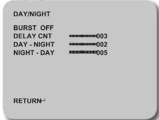
Selects whether to output the burst signal when night mode has been identified.
DELAY CNT: 000-255
Night/Day identification transfer time.
Threshold for Night status from day status.
Threshold for the Day status from night status.
- BW SETUP: Allows additional Smart IR settings to be enabled.
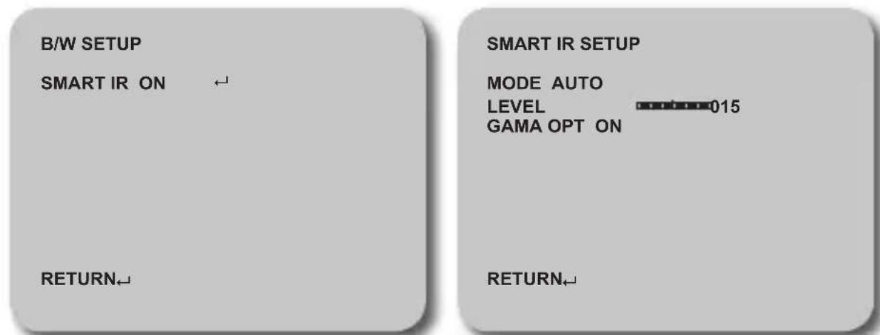
MODE: AUTO / CENTER

Center option under mode allows the user to define a rectangular area for the Front Light Compensation.
PRIVACY OFF / ON←

Hide an area so that it is not displayed on the monitor.
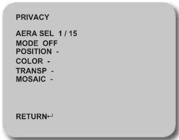
AREA SEL: Select the privacy area to be adjusted.
MODE: OFF / ON
When ON the settings below can be changed
Default OFF for all Areas

POSITION: When selected area selection screen appears:

Move the joystick to move the corners (you can create any 4-sided shape). The selected side is highlighted by a small box. To select the next corner, press ENTER. To return to privacy menu, press enter repeatedly.
COLOR: BLACK, RED, GEEEN, BLUE, YELLOW, CYAN, MAGENTA, WHITE. Sets the colors of the mask frames.
TRANSP: 1.00 / 0.75 / 0.50 / 0.00 Sets the privacy area transparency.
MOSAIC: ON/OFF Sets the privacy mask as mosaic. MOSAIC is not available if TRANSP is 1.00
MOTION DET

The motion detection areas of the screen are broken into 24 x 16 rectangular blocks. Use MONITOR AREA to configure always-on motion alert areas on the screen.
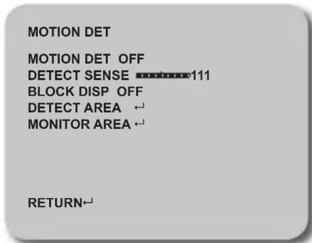
MOTION DET: OFF / ON. Turn on or off the motion detection. Default is OFF
DETECT SENSE: 0-127 Sets the motion detection sensitivity level.
BLOCK DISP: ON/OFF: Displays blocks in areas where motion is detected.
DETECT AREA: Select area of the screen to enable / disable motion detection.

Grid areas: Motion detection enabled Transparent: Motion detection disabled
By default the entire area is enabled for detection. Using the movement arrows you move the 2x2 size block positions around the screen. Press the enter button to toggle this area to enable/diable motion detection. Hold down the enter button to return to the motion detection menu.
MONITOR AREA :
Allows you to configure up to 4 motion detection areas. Areas will be highlighted on the screen and flash when motion is detected within them. Areas will not flash if motion is detected in areas that have been disabled using DETECT AREA.

AREA SEL: 1/4, 2/4, 3/4, 4/4 Select area to adjust.
When enabled, the box colors are:
1 Pink, 2 Green, 3 Blue, 4 Yellow
When areas overlap, the area with the lowest number takes priority
MODE: OFF / ON. Disable / Enable area
TOP: 000-015 Position of the top of the area
BOTTOM: 000-015 Position of the bottom of the area
LEFT: 000-023 Position of the left side of the area
RIGHT: 000-023 Position of the right side of the area
Note: TOP value cannot be greater than BOTTOM, and LEFT cannot be greater than RIGHT. Numbers automatically update to prevent invalid positions.
OTHERS

Miscellaneous camera functions.

• LENS MANUAL/AUTO ←

MODE: AUTO, OPEN, CLOSE
Sets the mechanical iris control mode.
SPEED: 000-255
Sets the convergence speed of the mechanical iris.
• CAM TITLE OFF / ON←
Select a camera title to be shown on the screen.
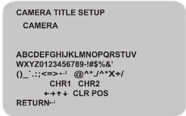
Use Up/Down/Left/Right to move around. CLR will clear info. POS allows you to change the title position.
• SYNC
Camera uses internal sync (INT) when camera is connected to DC power. Line Lock (LL) is used when camera is connected to AC power. If you notice color rolling when the camera is connected to AC power, select LL then select PHASE UP or PHASE DOWN and press ENTER to adjust the phase.

• WPC (Advanced function; not for normal use)

The WPC (White Pixel Compensation) features is used to correct the CCD if dead pixels are visible. You must cover the lens completely so no light can enter the camera sensor for WPC to work. Press the up, down, left, right, middle button to start the highlight of compensation. When prompts finish, press middle button to exit.
- VERSION
Gives version information regarding current camera software.
VERSION INFO
MCU VER V1.0.0 NORMAL
ROM VER V1.0.0
RETURN←
- CAMERA RESET
This will reset all settings for all menus to manufacturer defaults.
EXIT / SAVE ALL

- EXIT Exit OSD menu.
Exit will keep any changes only until camera is powered off.
• SAVE ALL Saves the settings to camera
Settings are retained after camera power loss.
Follow the steps below if you are experiencing trouble with your camera. Contact Digimerge Technical Support if the issue persists.
• Nothing appears on the screen.
☐ Check that the power cable is connected properly and that the voltage is correct.
☐ Check that you have properly connected VIDEO cable to the camera VIDEO output jack and to the monitor/DVR.
• The image on the screen is unclear.
☐ Is the lens or dome cover stained with dirt? Clean lens or dome cover with soft, clean cloth.
☐ Re-position the camera if necessary.
☐ Adjust the Zoom and Focus screws as needed.
• The image on the screen is dark.
☐ If you have an intermediate device, set the impedance to 75 / Hi-z .
- Adjust the monitor contrast & brightness controls.
• Image quality is poor.
☐ Return the camera OSD to factory default settings (OSD Menu>OTHERS>CAMERA RESET).
☐ Verify that the camera is receiving sufficient power.
• There is interference in the image.
☐ The camera or the cables may be close to a source of high voltage, such as a generator. Reposition the camera if necessary.
When the resistance value of copper wire is at [20^(68^)]
| Copper wire size (AWG) #24(0.22mm ^2 ) #22(0.33mm ^2 ) #20(0.52mm ^2 ) #18(0.83mm ^2 ) | ||
| Resistance (Ω/m) 0.078 0.050 0.030 0.018 | ||
| Voltage Drop (V/m) 0.028 0.018 0.011 0.006 |
As shown in the table above, voltage decreases as the wire gets longer. Therefore use of an excessively long adapter output line for connection to the camera may affect the performance of the camera.
*Standard voltage for camera operation : DC12V ±10% or AC24V ±10%
*There may be some deviation in voltage drop depending on the type of wire and the manufacturer.
- Be sure to connect power only after all the installation is complete.
• Use the UL listed, CLASS 2 power transformer for 12v DC or 24v AC adapter.
- WARNINGS AND CAUTIONS:
- CAUTION:
- CAUTION
- EXPLANATION OF GRAPHICAL SYMBOLS
- PRECAUTIONS
- Safety
- Installation
- Cleaning
- FCC COMPLIANCE STATEMENT
- CE COMPLIANCE STATEMENT
- WARNING
- READ AND RETAIN INSTRUCTIONS
- CLEANING
- ATTACHMENTS
- MOISTURE
- ACCESSORIES
- VENTILATION
- POWER SOURCES
- GROUNDING OR POLARIZATION
- CORD AND CABLE PROTECTION
- LIGHTNING
- OVERLOADING
- SERVICING
- DAMAGE REQUIRING SERVICE
- REPLACEMENT PARTS
- SAFETY CHECK
- FIELD INSTALLATION
- All Models Feature:
- DPD34D
- DPV34D
- SPECIFICATIONS
- JUNCTION BOX PLATE
- 2S FITTING
- 4S FITTING
- TWO GANG FITTING
- OCTAGON FITTING
- INSTALLATION. VANDAL DOME
- Method 1 - Direct Attach Install
- OR
- Method 2 - Camera Base Install
- Method 3 - Junction Box Install
- INSTALLATION. INDOOR DOME (Surface Fitting)
- INSTALLATION. INDOOR DOME (Semi-Flush Fitting)
- Thumb Screw
- 4
- MENU TREE SUMMARY
- OSD MENU control
- SETUP MENU
- EXPOSURE
- AUTO
- - MANUAL
- MODE: SHUT / SLOW
- PICT ADJUST
- Picture and display control settings
- Note: Zoom must be higher than 0 to use Pan and Tilt settings.
- WHITE BAL
- WDR
- • MODE: OFF / D-WDR
- DNR
- PRIVACY OFF / ON←
- MOTION DET
- MONITOR AREA :
- OTHERS
- • SYNC
- - VERSION
- - CAMERA RESET
- EXIT / SAVE ALL
Brand : Digimerge
Model : Pinnacle DPD34D
Category : Security Camera