Pinnacle DPB14TLX - Security Camera Digimerge - Free user manual and instructions
Find the device manual for free Pinnacle DPB14TLX Digimerge in PDF.


| Product Type | Ultra Resolution Day & Night Bullet Camera |
| Model | DPB14TLX |
| Image Sensor | 1/3" Sony Super HAD II CCD |
| Effective Pixels | H: 768, V: 494 (NTSC) |
| Scan System | 2:1 Interlace NTSC |
| Minimum Illumination | 0.15 Lux / F1.2 (Color); 0.001 Lux (Sense-Up x256); 0 Lux with IR LED |
| Resolution | 600 TV Lines (Color) |
| Lens | 2.8-10.5mm Varifocal, F1.4, DC Auto Iris |
| Viewing Angle (Horizontal / Vertical / Diagonal) | 96.7°~24.1° / 71.2°~18.2° / 124.3°~30.2° |
| Day/Night | True Day/Night with ICR (Infrared Cut Filter Removal) |
| IR Technology | Smart IR (0 Lux with IR LED) |
| Video Output | 1.0Vpp @ 75 Ohm, BNC Female |
| Power Source | 12V DC / 24V AC, Class 2 |
| Power Consumption | Max 8.4W |
| Operating Temperature | -40°C ~ 50°C |
| Dimensions (LxWxH) | 298 x 101 x 88 mm |
| Weight (approx.) | 0.6 kg (estimated) |
| Mounting | Wall mount, Octagon junction box compatible |
| Cleaning | Turn off and unplug; use damp cloth; avoid harsh cleansers |
| OSD Control | Yes, via service port with 5-button joystick |
| Special Features | 3D-DNR, Privacy Masking, Motion Detection, Digital Zoom (1x~32x), D-Effects |
| Warranty | Refer to manufacturer; service by qualified personnel |
Frequently Asked Questions - Pinnacle DPB14TLX Digimerge
User questions about Pinnacle DPB14TLX Digimerge
0 question about this device. Answer the ones you know or ask your own.
Ask a new question about this device
Download the instructions for your Security Camera in PDF format for free! Find your manual Pinnacle DPB14TLX - Digimerge and take your electronic device back in hand. On this page are published all the documents necessary for the use of your device. Pinnacle DPB14TLX by Digimerge.
USER MANUAL Pinnacle DPB14TLX Digimerge
natural_image
Technical line drawing of a mechanical assembly with gears and housing (no text or symbols)Ultra Resolution
Day & Night Bullet Camera
www.diglmerge.com
V3.0
Models: DPB14TLX
Please read this manual thoroughly before use and keep it handy for future reference.
IMPORTANT SAFEGUARDS
1. READ AND RETAIN INSTRUCTIONS
Read the instruction manual before operating the equipment. Retain the manual for future reference.
2. CLEANING
Turn the unit off and unplug from the power outlet before cleaning. Use a damp cloth for cleaning. Do not use harsh cleansers or aerosol cleaners.
3. ATTACHMENTS
Do not use attachments unless recommended by the manufacturer as they may affect the functionality of the unit and result in the risk of fire, electric shock or injury.
4. MOISTURE
Do not use equipment near water or other liquids.
5. ACCESSORIES
Equipment should be installed in a safe, stable location. Any wall or shelf mounting accessory equipment should be installed using the manufacturer's instructions. Care should be used when moving heavy equipment. Quick stops, excessive force, and uneven surfaces may cause the equipment to fall causing serious injury to persons and objects.
6. VENTILATION
Openings in the equipment, if any, are provided for ventilation to ensure reliable operation of the unit and to protect if from overheating. These openings must not be blocked or covered
7. POWER SOURCES
The equipment should be operated only from the type of power source indicated on the marking label. If you are not sure of the type of power supplied at the installation location, contact your dealer. For equipment designed to operate from battery power, refer to the operating instructions.
8. GROUNDING OR POLARIZATION
Equipment that is powered through a polarized plug (a plug with one blade wider than the other) will fit into the power outlet only one way. This is a safety feature. If you are unable to insert the plug fully into the outlet, try reversing the plug. Do not defeat the safety purpose of the polarized plug.
Alternate Warning: If the equipment is powered through a three-way grounding-type plug, a plug having a third (grounding) pin, the plug will only fit into a grounding-type power outlet. This is a safety feature. Do not defeat the safety purpose of the grounding-type plug. If your outlet does not have the grounding plug receptacle, contact your local electrician.
9. CORD AND CABLE PROTECTION
Route power cords and cables in a manner to protect them from damage by being walked on or pinched by items places upon or against them.
10. LIGHTNING
For protection of the equipment during a lightning storm or when it is left unattended and unused for long periods of time, unplug the unit from the wall outlet. Disconnect any antennas or cable systems
that may be connected to the equipment. This will prevent damage to the equipment due to Lightning or power-line surges.
11. OVERLOADING
Do not overload wall outlets and extension cords as this can result in a risk of fire or electric shock.
12. SERVICING
Do not attempt to service the video monitor or equipment yourself as opening or removing covers may expose you to dangerous voltage or other hazards. Refer all servicing to qualified service personnel.
13. DAMAGE REQUIRING SERVICE
Unplug the equipment from the wall outlet and refer servicing to qualified service personnel under the Following conditions:
A. When the power supply cord or the plug has been damaged.
B. If liquid has spilled or objects have fallen into the Unit
C. If the equipment has been exposed to water or other liquids.
D. If the equipment does not operate normally by following the operating instructions, adjust only those controls that are covered by the operating instructions. Improper adjustment of other controls may result in damage to the unit.
E. If the equipment has been dropped or the casing Damaged.
F. When the equipment exhibits a distinct change in performance.
14. REPLACEMENT PARTS
When replacement parts are required, be sure the service technician uses replacement parts specified by the manufacturer or that have the same characteristics as the original part. Unauthorized substitutions may result in fire, electric shock, or other hazards.
15. SAFETY CHECK
Upon completion of any service or repairs to the equipment, ask the service technician to perform safety checks to verify that the equipment is in proper operating condition.
16. FIELD INSTALLATION
The installation of equipment should be made by a qualified service person and should conform to all local codes.
- CAUTION-these servicing instructions are for use by qualified service personnel only, to reduce the risk of electric shock do not perform any servicing other than that contained in the operating instructions unless you are qualified to do so.
17-1 Regulated Class 2 power source only.
17-2 Do NOT use power source other than that specified.
INTRODUCTION
Features
• 1/3" Sony Super HAD™ II CCD
• Excellent low light performance using
Polaris Vision 2 technology
• Smart IR technology
- 0.15 Lux / F1.2 (Color) 0.001 Lux w/Sense-Up at x256 0.0 w/IR LED
• 600 TV lines(Color) of resolution
• 3D Digital Noise Reduction (3D-DNR)
- OSD menu control
• True Day/Night with ICR
• Privacy Masking / Motion Detection
• VIDEO OUT(BNC)
• Test Monitor Output
• 2.8-10.5mm Varifocal Day/Night Lens F1.4 DC Iris
- Octagon junction box compatible
SPECIFICATIONS
| GeneralDPB14TLX | |
| Image Sensor | 1/3" Sony Super HADTM II CCD |
| Effective Pixel | H: 768 V: 494 |
| Effective Pixel Area | H: 5.59mm V: 4.68mm |
| Scan System | 2:1 Interlace NTSC |
| Scan Frequency | H: 15.734KHz, V: 59.94Hz |
| Synchronization | Internal |
| Minimum Illumination | 0 Lux IR LED On |
| S/N Ratio | 50dB @ AGC Off |
| Resolution | 600 TV Line |
| White Balance | Auto 1800°K ~ 10500°K |
| AES Speed | 1/60~1/100000 Sec |
| Gain Control | Auto |
| BLC | Manual |
| Video Output | 1.0Vpp @ 75 ohm |
| Termination | BNC Female |
| Lens/ Lens Mount | 2.8-10.5mm F 1.4 Varifocal DC Auto Iris |
| Viewing Angle | H: 96.7° ~ 24.1°, V: 71.2° ~ 18.2°, D: 124.3° ~ 30.2° |
| Power Source | 12V DC / 24V AC |
| Power Consumption | Max 8.4W |
| Minimum Power Requirement | 700mA |
| Operating Temp Range | -40°C ~ 50°C |
| Operating Range | Within 90% RH |
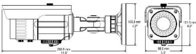
| Dimensions (LxHxW) | 298x101x88 mm |
| Gamma | 0.45 |
MEASUREMENTSINSTALLATION
PACKAGING CONTENT
Bullet package contains the following:
Camera in housing 1
Instruction guide (This Document)----1
Mounting screw pack 1
Service Video Cable 1
Sunshield Screw (fitted to camera)----1
Allen Key----1

(A) Wall Plugs
58 x 30mm 4pcs

(8) Fitting Screws
PA4 x 35mm 4pcs

(C) Sunshield Screw
M5 Thread

(D) Allen Key
47×17mm
PARTS DESCRIPTION

natural_image
Technical line drawing of a mechanical assembly with no visible text or symbolsZoom Adjust ServiBnAocAdjRien / Tilt Adjustment 380 Rubale Rubale Lcn
Thread Nur
1

natural_image
Line drawing of a handheld electric drill with a circular head and base (no text or symbols)2
C
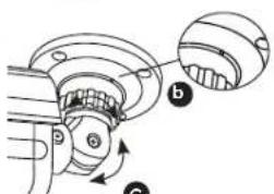
1a) Loosen the thread nut with the included allen key and turn the camera base counter clockwise to remove it from the camera mount.
1b) Mount the camera base to the surface.
NOTE: The camera base is compatible with an Octagon junction box
2a) Attach camera back onto the camera base by turning it counter clockwise.
2b) Tighten the thread nut to secure the camera's horizontal angle.
2c) Use a Phillips head screwdriver to adjust the vertical viewing angle of the camera.
3) Adjust lens zoom and focus turning the two external adjustment screws located on the underside of the camera. Adjustment can be made using fingers, or with use of a flat head screwdriver.
3

4

4) OSD Settings and video test port are accessed via the service access port on the underside of the camera. Turn counter-clockwise to remove the cap.
Note: Apply considerable pressure when replacing the cap to keep camera weather proof.
CAMERA ADJUSTMENT CAMERA ADJUSTMENT
Menu Setup

Service Connector output.
Use supplied cable to connect to this
output

natural_image
Circular diagram with six connected components and a label 'GSD function controls' at the bottom (no readable text or symbols beyond basic labels)OSD function controls.
Pressing down on middle button
acts as ENTER function.
MENU TREE SUMMARY
LENS • DC
EXPOSURE • SHUTTER • AGC • SENS-UP • BLC • D-WDR • RETURN
WHITE BAL • AWB • ATW • AWC SET • OUTDOOR • INDOOR • MANUAL
3DNR • OFF • ON
SPECIAL • CAM TITLE • D-EFFECT • MOTION • PRIVACY
- SYNC • LANGUAGE
ADJUST • SHARPNESS • MONITOR • OSD COLOR
RESET • FACTORY • RETURN
- Press ENTER on the function buttons to access the setup menu.
- Main setup menu is displayed on the monitor screen.

- Select a function by pressing up and down and move left or right buttons to change setting value and press ENTER to confirm selection.
- If a menu option features a ☑, a sub menu is available which can be accessed by pressing the ENTER button
- Once finished updating settings, highlight 'EXIT' and press ENTER to exit setup menu
LENS
- Highlight 'LENS' in the main setup menu.
- Press ENTER to access the LENS setting menu.

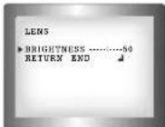
DC : Select Auto Iris Lens
- When DC is selected, you can control screen brightness. The range of brightness control is between 1 and 100. Adjust the brightness appropriately for optimal screen brightness. Default value is 50
EXPOSURE
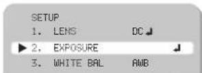
The EXPOSURE menu is used to set the automatic light control method for the camera.
- Highlight 'EXPOSURE' in the main setup menu
- Press ENTER to access the exposure setup menu.

SHUTTER : Select the shutter mode. (1/60, FLK - 1/100,000 sec, x2 - 256) Default setting is 1/60
BRIGHTNESS: The brightness level can be adjusted within the range of 0 - 100. Default setting - 50
AGC: Auto gain control (LOW / MIDDLE / HIGH) Default setting is MIDDLE
CAMERA ADJUSTMENT CAMERA ADJUSTMENT
SENSE-UP
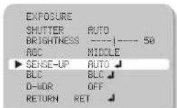
Select digital slow shutter speed setting in order to allow extra light into the camera thereby providing higher sensitivity in low light conditions. NOTE only adjustable if SHUTTER setting is set to 'AUTO' or '1/60'
- OFF: Deactivates the SENS-UP function.
- AUTO : Activates SENS-UP function. Enter submenu to select maximum low shutter value
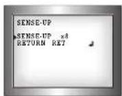
Selectable low shutter values are as follows:
x2 x4 x8 x16 x32 x64 x128 x 256 (default - x8)
For proper setup, check setting during low light / night time conditions.
Notes
- It's recommended to keep the value in the x2 to x64 range to limit ghosting effect.
BACKLIGHT (BLC)
The BLC menu is used to adjust backlight compensation function to sharpen subjects in backlight situations
- Highlight 'BLC' in the exposure setup menu.
- Press the ENTER to access the BLC setup menu.
BLC (Backlight Compensation):
Enter the BLC submenu to select an area in the scene which requires enhancing. Change the GAIN value (LOW/MIDDLE/HIGH) to set level of enhancement.
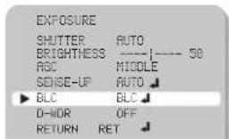


HSBLC (Highlight Compensation):
If a scene contains very bright light sources (e.g. car headlights), they will be masked to provide greater detail in the rest of the scene. Enter the HSBLC submenu to select an area in the scene which requires masking. Change the LEVEL value to set level of masking and change MODE to set whether to mask all day long or during low light conditions only.
Default setting is OFF
CAMERA ADJUSTMENT CAMERA ADJUSTMENT
Wide Dynamic Range (E-WDR)
D-WDR: The D-WDR menu is used to adjust dynamic range of the camera electronically. This is especially useful in high contrast scenes in order to brighten up darker parts of the scene.
- Highlight 'D-WDR' in the exposure setup menu.
- Move buttons left and right to change setting to OFF/INDOOR/OUTDOOR. Default setting is OFF

INDOOR : Preferred setting when camera is installed indoors. Default settings are LOW-6 and HIGH-9
OUTDOOR:: Preferred setting when camera is installed outdoors. Default settings are LOW-11 and HIGH-11

White Balance (White Bal.)
White balance function adjusts displayed colors to account for different lighting temperatures.
- Highlight 'WHITE BAL' in the main setup menu.
- Press the left/right buttons to change setting to: AWB/AWC->SET/MANUAL/INDOOR/OUTDOOR/ATW Default setting is AWB (Auto White Balance)

AWB(Automatic White Balance) : This mode automatically adjusts white balance
AWC-SET: To obtain the optimum state under the current lumin levels, direct the camera to point toward a sheet of white paper and press the SET button. If the environment changes, including the light source, the white balance will require re-adjustment.
MANUAL: The manual adjustment setting enables detailed color adjustment. Select 'ATW' or 'AWB' first then change to 'MANUAL' adjustment setting and press ENTER. Set the appropriate color temperature by increasing / decreasing the red and blue color values and monitor the color changes of the object. Default settings are BLUE-41, RED-45
INDOOR : Select this when the color temperature is between 4,500°K and 8,500°K.
OUTDOOR : Select this when the color temperature is between 1,800°K and 10,500°K. (sodium light)
ATW(Auto Tracking White Balance): This mode can be used within the color temperature range 1,800°K \~ 10,500°K

Notes
- White Balance may not work properly under the following conditions. In this case select the AWC mode.
1 When the color temperature of the environment surrounding the subject is outside of the supported temperature range (e.g. clear sky or sunset).
2 When the ambient illumination of the subject is dim.
3 If the camera is directed towards a fluorescent light or is installed in a place where illumination changes dramatically, the White Balance function may become unstable.
CAMERA ADJUSTMENT CAMERA ADJUSTMENT
Digital Noise Reduction (3D DNR)
This function reduces the background noise in a low luminance environment.
- Highlight '3DNR' in the main setup menu.

- Press the left/right buttons to change setting to OFF/ON
OFF - Noise is not reduced
ON - Noise is reduced
- Press ENTER to access the submenu for ON setting.
In the 3DNR submenu you can adjust the noise reduction level values range from 0 to 100. Default setting is 60.
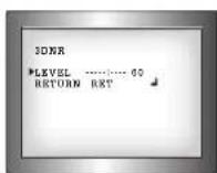
Notes
- Noise levels can be very subtle, and may not be always noticeable on adjusting
- When adjusting the noise reduction level in 3DNR submenu, remember that the higher the level set, the more the noise level will be reduced, however this can have a softening effect on the image.
SPECIAL.
- Highlight 'SPECIAL' in the main setup menu.

- Press ENTER to access the submenu for SPECIAL settings.

○ CAM TITLE: If you enter a title, the title will appear on the monitor.
- Press left/right buttons to change setting to OFF/ON OFF - No camera title is displayed ON - Camera title is displayed
CAMERA ADJUSTMENT CAMERA ADJUSTMENT
Notes
*When the CAM TITLE is OFF no title will be displayed on the monitor even if you had previously setup a name. This is the master display setting.
- Only English is available in this mode for camera title.
- Only max 15 characters for the title allowed.
- Press ENTER to access the submenu for ON setting. Here you will be able to enter the camera title.
CAN TITLE
0123455789
PRODEFINIC
LMNOPORSTUU
HXYZ→+↑↓()
- ■ = & : √
← → CLR POS END
- - - - - - - - - -
- Press left/right/up/down buttons to select a letter/number/symbol and press ENTER to confirm selection. Repeat steps until camera title is completed and select 'POS' to select on-screen location for title and 'END' to save title. You can enter up to a maximum of 15 characters.
Notes
- If you move the cursor to CLR and press the ENTER, all the letters are deleted. To edit a letter, change the cursor to the bottom left arrow and press ENTER. Move the cursor over the letter to be edited, move the cursor to the letter to be inserted and then press the ENTER.
D-EFFECT: Applies digital effects to camera image. 1. Highlight 'D-EFFECT' in the SPECIAL setup menu.
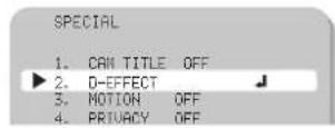
- Press ENTER to access the submenu.
Notes

-
FREEZE: Freezes current image displayed
-
MIRROR: MIRROR will mirror the image. V-FLIP, will flip the image vertically. ROTATE, will vertically flip and also mirror. OFF, no image effect applied.
-
D-ZOOM: Allows digital zoom and position to be set.

Digital Zoom can range from 1x to 32x. Too much digital zoom will result in blocky image Pan / Tilt range is -100 to 100.
CAMERA ADJUSTMENT CAMERA ADJUSTMENT
MOTION:
You can monitor activity more efficiently, because a signal is generated by the camera whenever motion is detected. Visual notification is also available.
- Highlight 'MOTION' in the SPECIAL setup menu

-
Press left/right buttons to change setting to OFF/ON
-
Press ENTER to access the submenu for ON setting


- AREA SELECT: Select motion detection area number. AREA 1-4 With the area selected will be shown flashing on and off visually.
- AREA DISPLAY: Turns selected motion detection area ON or OFF. Pressing ENTER when ON will change display to set the position and the size of the area. Pressing the direction buttons will change the setting, and press ENTER to accept. After you have set both position, size you can RET or AGAIN
- SENSITIVITY: Adjust sensitivity for selected motion detection area (0-40).
- MOTION VIEW: Turn motion detection view ON or OFF. When turned on, upon detection of motion, motion is shown as green dots to indicate area in which motion is taking place.

- Motion detection is normally part of a DVR which would provide more flexible customization options.
PRIVACY:
Hide an area so that it is not displayed on the monitor.
- Highlight 'PRIVACY' in the SPECIAL setup menu.
- Press left/right buttons to change setting to OFF/ON
-
Press ENTER to access the submenu for ON setting
-
AREA SELECT: Select privacy area number, AREA 1-8
With the area slected will be shown flashing on and off visually. - AREA DISPLAY: Turns selected privacy area ON or OFF.
Pressing ENTER when ON will change display to set
the position and the size of the area. Press direction buttons
will change the setting, and press ENTER to accept.
After you have set both position, size you can RET or AGAIN - COLOR: Range 0-15. Sets the color of the selected privacy area.
SYNC:
With 24V AC power source, select INT / EXT for Sync, use left/right to select.
LANGUAGE:
The OSD supports English, Korean, Japanese, Chinese, Simplified Chinese, Russian
DEFECT:
For Service use only!
ADJUST
ADJUST:
SHARPNESS: Image edge sharpness 0 (soft image) to 31 oversharp (default is 12)
MONITOR: CRT/LCD/USER setting for monitor type Note: For direct monitor connection only. (default is CRT)
OSD COLOR: 0-15 color for OSD menu text (default is 3)
RESET
RESET:
This will reset all settings for all menus to manufacturer defaults. This allows you to return to shipped settings from the manufacturer.


TROUBLESHOOTING
Refer to the following table if you are experiencing trouble with your camera. Contact an authorized technician if the table does not provide you with a solution to the trouble.
● Nothing appears on the screen.
K Check that the power cord and line connection between the camera and monitor are connected properly.
K Check that you have properly connected VIDEO cable to the camera VIDEO output jack.
● The image on the screen is dim.
K Is lens stained with dirt? Clean lens with soft, clean cloth.
8 Adjust the monitor contrast & brightness controls
g. Re-position the camera if necessary.
● The image on the screen is dark.
- Adjust the contrast feature of the monitor.
g. If you have an intermediate device set the 75Ω / H-z properly.
● The camera is not working properly, and the surface of the camera is hot.
E Check that you have properly connected the camera to an appropriate power source.
● The Motion Detection function does not work.
- Check that MOTION DEF of SPECIAL SETUP menu is 'ON' for the selected area.
● Color is not correct.
R Check the setting of WHITE BAL SETUP menu.
- When the resistance value of copper wire is at [20°C(68°F)]
| Copper wire size (AWG) | \#24(0.22mm^2) | \#22(0.33mm^2) | \#20(0.52mm^2) | \#18(0.83mm^2) |
| Resistance ( /m ) | 0.078 | 0.050 | 0.030 | 0.018 |
| Voltage Drop (V/m) | 0.028 | 0.018 | 0.011 | 0.006 |
As shown in the table above, voltage decreases as the wire gets longer. Therefore use of
an excessively long adaptor output line for connection to the camera may affect the
performance of the camera.
*Standard voltage for camera operation: AC 24V +10% or DC 12V +10%
*There may be some deviation in voltage drop depending on the type of wire and the manufacturer.
Notes
- Be sure to connect power only after all the installation is complete.
- Use the UL listed, class 2power transformer of AC24V adaptor.
- IMPORTANT SAFEGUARDS
- READ AND RETAIN INSTRUCTIONS
- CLEANING
- ATTACHMENTS
- MOISTURE
- ACCESSORIES
- VENTILATION
- POWER SOURCES
- GROUNDING OR POLARIZATION
- CORD AND CABLE PROTECTION
- LIGHTNING
- OVERLOADING
- SERVICING
- DAMAGE REQUIRING SERVICE
- REPLACEMENT PARTS
- SAFETY CHECK
- FIELD INSTALLATION
- INTRODUCTION
- Features
- CAMERA ADJUSTMENT CAMERA ADJUSTMENT
- LENS
- SENSE-UP
- Notes
- BACKLIGHT (BLC)
- Wide Dynamic Range (E-WDR)
- White Balance (White Bal.)
- Digital Noise Reduction (3D DNR)
- SPECIAL.
- MOTION:
- PRIVACY:
- SYNC:
- LANGUAGE:
- DEFECT:
- ADJUST
- ADJUST:
- RESET
- RESET:
- TROUBLESHOOTING
Brand : Digimerge
Model : Pinnacle DPB14TLX
Category : Security Camera