
T040-001-HDMI - Computer Accessories Tripp Lite - Free user manual and instructions
Find the device manual for free T040-001-HDMI Tripp Lite in PDF.


| Product Type | HDMI Cable Tester |
| Brand | Tripp Lite |
| Model | T040-001-HDMI |
| Compatibility | HDMI versions 1.0 through 2.1 |
| Connector Types | HDMI Type A-A, A-C, C-C |
| Test Modes | Continuity (sync) and Sweep (step-by-step) |
| Cable Length Support | Up to 164 ft (50 m) |
| Power Source | 9V battery (not included) |
| Package Contents | Main Tester, Remote Identifier, Carrying Case, Owner's Manual |
| Dimensions (Main Tester) | Approx. 5.7 x 3.0 x 1.2 in (145 x 76 x 30 mm) |
| Weight (Main Tester) | Approx. 0.5 lb (227 g) |
| Display | 19 LED indicators for pins + shield |
| Wire Map Verification | Pin-to-pin continuity and shield status |
| Fault Detection | Open circuit, short circuit, crossed connections |
| Warranty | 1-Year Limited |
| FCC Compliance | Class B |
| Maintenance | Replace 9V battery as needed; clean with dry cloth |
| Safety | Not for use in life support applications; avoid moisture |
| Spare Parts | 9V battery (user-replaceable) |
| General Information | All-in-one tester with removable remote identifier; includes carrying case |
Frequently Asked Questions - T040-001-HDMI Tripp Lite
User questions about T040-001-HDMI Tripp Lite
0 question about this device. Answer the ones you know or ask your own.
Ask a new question about this device
Download the instructions for your Computer Accessories in PDF format for free! Find your manual T040-001-HDMI - Tripp Lite and take your electronic device back in hand. On this page are published all the documents necessary for the use of your device. T040-001-HDMI by Tripp Lite.
USER MANUAL T040-001-HDMI Tripp Lite
Register your product for quicker service and ultimate peace of mind. You could also win an ISOBAR6ULTRA surge protector—a \$100 value! www.tripplite.com/warranty


1111 W. 35th Street, Chicago, IL 60609 USA • www.tripplite.com/support
Copyright © 2017 Tripp Lite. All rights reserved.
Package Contents
- Master Unit
- Carrying Case
- Remote Unit
- Owner's Manual
Product Features
- All-in-one unit combines a Main Tester with a removable Remote Identifier
- Compatible with HDMI versions 1.0 through 2.1
- Fast and accurate verification of HDMI cables with Type A-A, A-C or C-C connectors
- Displays 19 pin-to-pin wire map and shield connection status to ensure mapping continuity and proper configuration
- Two adjustable test modes available: Continuity and Sweep
Operation
Note: Before testing, insert a 9V battery (not included) and ensure the cable being tested is not yet connected to the tester.
Testing
Simply connect the desired cable to the unit, then switch the Sweep/OFF/Continuity button to “Continuity” for sync testing, or “Sweep” for step-by-step testing.
Note: During sync testing, all LEDs illuminate on the wire map at once. During step-by-step testing, the LEDs will illuminate one at a time.
When testing uninstalled patch cable, you can leave the Main Tester and Remote Identifier connected.
When testing installed cable, you will need to remove the Remote Identifier from the Main Tester. Connect one end of the cable to the appropriate connector on the Main Tester, and the other end of the cable to the appropriate connector on the Remote Identifier.
Note: Upon switching to the desired testing mode, the LEDs on the Main Tester and Remote Identifier will illuminate to indicate the results.
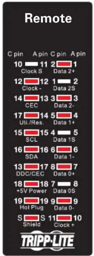
If testing HDMI A-to-A cables, use “A pin” side numbers found on both the Main Tester and Remote Identifier. For HDMI A-to-C and C-to-C cables, use “C pin” side numbers found on both the Main Tester and Remote Identifier.
Detecting Connections
Note: This product is designed to test cable lengths up to 164 ft. (50 m).
When a cable connection from both ends is detected, the LEDs will illuminate. Listed below are detected connection examples with diagrams showing which pins should illuminate for each connection type.
Note: When no connection is detected between the connectors of the cable being tested, the LEDs will not illuminate
Straight (Proper) Connection
When all LEDs illuminate on both the Master and Remote units, the cable is properly wired and ready to install/use.


Detecting Connections
Crossed Connection
If the wires inside the cable are out of order or crossed, the LEDs on the Remote Identifier will illuminate to show in what order they are wired. For example, in the diagram below, when the Master unit shows pin 14 illuminated, pin 19 on the Remote unit will illuminate, indicating those connections are crossed.
Note: Crossed connections cannot be tested in "Continuity" mode.

Detecting Connections
Open Circuit
If the same LEDs on both the Master and Remote units remain off, the corresponding wire is an open circuit.

Detecting Connections
Short Circuit
If a short circuit is detected, the Remote unit's LEDs will not illuminate, but the Master units LEDs will illuminate brighter.


Warranty and Product Registration
1-YEAR LIMITED WARRANTY
TRIPP LITE warrants its products to be free from defects in materials and workmanship for a period of one (1) year from the date of initial purchase. TRIPP LITE's obligation under this warranty is limited to repairing or replacing (at its sole option) any such defective products. To obtain service under this warranty, you must obtain a Returned Material Authorization (RMA) number from TRIPP LITE or an authorized TRIPP LITE service center. Products must be returned to TRIPP LITE or an authorized TRIPP LITE service center with transportation charges prepaid and must be accompanied by a brief description of the problem encountered and proof of date and place of purchase. This warranty does not apply to equipment, which has been damaged by accident, negligence or misapplication or has been altered or modified in any way. EXCEPT AS PROVIDED HEREIN, TRIPP LITE MAKES NO WARRANTIES, EXPRESS OR IMPLIED, INCLUDING WARRANTIES OF MERCHANTABILITY AND FITNESS FOR A PARTICULAR PURPOSE.
Some states do not permit limitation or exclusion of implied warranties; therefore, the aforesaid limitation(s) or exclusion(s) may not apply to the purchaser.
EXCEPT AS PROVIDED ABOVE, IN NO EVENT WILL TRIPP LITE BE LIABLE FOR DIRECT, INDIRECT, SPECIAL, INCIDENTAL OR CONSEQUENTIAL DAMAGES ARISING OUT OF THE USE OF THIS PRODUCT, EVEN IF ADVISED OF THE POSSIBILITY OF SUCH DAMAGE. Specifically, TRIPP LITE is not liable for any costs, such as lost profits or revenue, loss of equipment, loss of use of equipment, loss of software, loss of data, costs of substitutes, claims by third parties, or otherwise.
Product Registration
Visit www.triplite.com/warranty today to register your new Tripp Lite product. You'll be automatically entered into a drawing for a chance to win a FREE Tripp Lite product!*
* No purchase necessary. Void where prohibited. Some restrictions apply. See website for details.
FCC Notice, Class B
This device complies with part 15 of the FCC Rules. Operation is subject to the following two conditions: (1) This device may not cause harmful interference, and (2) this device must accept any interference received, including interference that may cause undesired operation.
Note: This equipment has been tested and found to comply with the limits for a Class B digital device, pursuant to part 15 of the FCC Rules. These limits are designed to provide reasonable protection against harmful interference in a residential installation. This equipment generates, uses and can radiate radio frequency energy and, if not installed and used in accordance with the instructions, may cause harmful interference to radio communications. However, there is no guarantee that interference will not occur in a particular installation. If this equipment does cause harmful interference to radio or television reception, which can be determined by turning the equipment off and on, the user is encouraged to try to correct the interference by one or more of the following measures:
- Reorient or relocate the receiving antenna.
- Increase the separation between the equipment and receiver.
- Connect the equipment into an outlet on a circuit different from that to which the receiver is connected.
- Consult the dealer or an experienced radio/TV technician for help.
Any changes or modifications to this equipment not expressly approved by Tripp Lite could void the user's authority to operate this equipment.
WEEE Compliance Information for Tripp Lite Customers and Recyclers (European Union)

Under the Waste Electrical and Electronic Equipment (WEEE) Directive and implementing regulations, when customers buy new electrical and electronic equipment from Tripp Lite they are entitled to:
- Send old equipment for recycling on a one-for-one, like-for-like basis (this varies depending on the country)
- Send the new equipment back for recycling when this ultimately becomes waste
Use of this equipment in life support applications where failure of this equipment can reasonably be expected to cause the failure of the life support equipment or to significantly affect its safety or effectiveness is not recommended.
Tripp Lite has a policy of continuous improvement. Specifications are subject to change without notice.


Manufacturing Excellence.
1111 W. 35th Street, Chicago, IL 60609 USA • www.tripplite.com/support
17-10-413 93-3794_RevA
- PACKAGE CONTENTS
- PRODUCT FEATURES
- OPERATION
- TESTING
- DETECTING CONNECTIONS
- STRAIGHT (PROPER) CONNECTION
- CROSSED CONNECTION
- OPEN CIRCUIT
- SHORT CIRCUIT
- WARRANTY AND PRODUCT REGISTRATION
- 1-YEAR LIMITED WARRANTY
- PRODUCT REGISTRATION
- FCC NOTICE, CLASS B
- WEEE COMPLIANCE INFORMATION FOR TRIPP LITE CUSTOMERS AND RECYCLERS (EUROPEAN UNION)
Brand : Tripp Lite
Model : T040-001-HDMI
Category : Computer Accessories