TER-F01 - Répéteur Ethernet Hanwha - Free user manual and instructions
Find the device manual for free TER-F01 Hanwha in PDF.

User questions about TER-F01 Hanwha
0 question about this device. Answer the ones you know or ask your own.
Ask a new question about this device
Download the instructions for your Répéteur Ethernet in PDF format for free! Find your manual TER-F01 - Hanwha and take your electronic device back in hand. On this page are published all the documents necessary for the use of your device. TER-F01 by Hanwha.
USER MANUAL TER-F01 Hanwha
text_image
WISENET TER-F01 IN OUTTER-F01 Series
10/100 MBPS ETHERNET REPEATER WITH 60 W PASS-THROUGH POE
This manual serves the following Model Names:
TER-F01
TER-F01PD
The TER-F01 series is an Ethernet repeater supporting up to 60 watts of Pass-through PoE, providing a simple and cost-effective way to extend Ethernet signals beyond the standard Ethernet 328 foot (100 meter) limit. The TER-F01 can be used to double the distance to 656 feet (200 meters) or multiple units can be combined in series with each unit providing an additional 328 feet (100 meters). The TER-F01 is powered by pass-through PoE from a PoE switch or midspan injector, requiring no local power. Low power consumption ensures that maximum power is made available to the remote PD device.
The standard configuration passes through the PoE to the next device, or as a PD model, which acts as the final PoE unit in the chain and does not pass through the PoE.
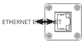
FIGURE 1 - TER-F01[PD] EXTENDER
text_image
ETHERNET ET NET
text_image
Wisenet TER-F01 IN OUT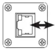
Note: Ports are universal, and either can be used as in or out.
Power: Supplied by PSE
Power Consumption: <1 W
FIGURE 3 – INDICATING LEDS
| COPPER | |
| GREEN | Solid - No ActivityBlinking - Activity |
| YELLOW | Highest Data Rate(100Mb) |
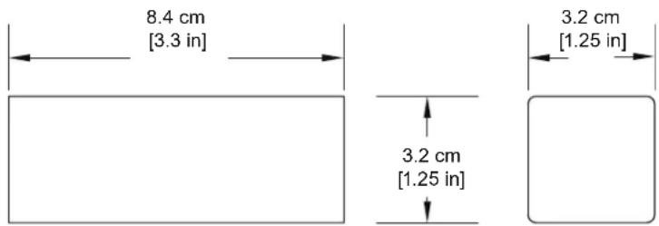
FIGURE 4 - DIMENSIONS
Dimensions are for a tube module
text_image
8.4 cm [3.3 in] 3.2 cm [1.25 in] 3.2 cm [1.25 in]INSTALLATION CONSIDERATIONS
The TER-F01[PD] is supplied as a 3.3 × 1.25 × 1.25 in (8.4 × 3.2 × 3.2 cm) tube module.
Units should be installed in dry locations protected from extremes of temperature and humidity.
WARNING: Unit is to be used with a Listed Class 2 power supply.
IMPORTANT SAFEGUARDS:
A) Elevated Operating Ambient - If installed in a closed or multi-unit rack assembly, the operating ambient temperature of the rack environment may be greater than room ambient. Therefore, consideration should be given to installing the equipment in an environment compatible with the maximum ambient temperature ( T_ma ) specified by the manufacturer.
B) Reduced Air Flow - Installation of the equipment in a rack should be such that the amount of air flow required for safe operation of the equipment is not compromised.
SPECIFICATIONS
Ethernet
Data Interface 10/100BaseT(X) Ethernet
IEEE 802.3 Compliant
Full Duplex or Half Duplex Electrical Ports
Standards IEEE: 802.3af PoE, 802.3at PoE+
RFC: 768 UDP, 2068 HTTP, 793 TCP, 791 IP, 1783
TFTP, 894 IP over Ethernet, 2544 TCP/IP Packet
Transmission
Transmission Distances ^1 See chart below
Connectors
Ethernet 2 × RJ-45
Power
Pass-Through Mode Operates on PoE Power
Power Consumption < 1 W
Protection High Impedance PoE Pass-Through with Start-up
Voltage Detection and Current Limiting
Mechanical
Indicating LEDs Ethernet Link and Activity
Circuit Board Meets IPC Standard
TER-F01[/PD] Size 3.3 × 1.25 × 1.25 in (8.4 × 3.2 × 3.2 cm)
Shipping Weight <1 lbs./0.5 kg
Environmental
MTBF >100,000 hours
Operating Temp - 40°C to +75°C
Storage Temp - 40°C to +80°C
Relative Humidity 0% to 95% (non-condensing) ^2
AGENCY COMPLIANCE


MAXIMUM TRANSMISSION DISTANCES ^1
| Maximum Range & Repeaters for PoE Power (Watts) | ||||||
| PoE Source | No PoE^3 | 5 W | 10 W | 15W | 20 W | 25 W |
| 15 W PoE Switch | 2,625 ft800 m(Using 7 TER-F01) | 1,476 ft450 m(Using 4 TER-F01) | 984 ft300 m(Using 2 TER-F01) | 328 ft^4 100 m^2 (No TER-F01) | N/A^4 | N/A^4 |
| 30 W PoE+ Switch | 2,625 ft800 m(Using 7 TER-F01) | 1,969 ft600 m(Using 5 TER-F01) | 1,316 ft400 m(Using 3 TER-F01) | 984 ft300 m(Using 2 TER-F01) | 656 ft200 m(Using 1 TER-F01) | 328 ft^4 100 m^2 (No TER-F01) |
| 35 W PoE+ Injector | 3,773 ft1,150 m(Using 11 TER-F01) | 2,625 ft800 m(Using 7 TER-F01) | 1,804 ft550 m(Using 5 TER-F01) | 1,316 ft400 m(Using 3 TER-F01) | 984 ft300 m(Using 2 TER-F01) | 656 ft200 m(Using 1 TER-F01) |
[1] Distance figures are based on 48V PSE PoE power source for PoE switches, 50V PSE PoE power source for PoE+ switches and 56V PSE PoE power source for the injector as detailed in the table. Distance figures are obtained using in-house testing mirroring installations. Factors such as cable quality, the number of connectors and splices in the cable run, the use of PoE, and environmental conditions encountered within the installation might affect the actual transmission distance and should be taken into consideration.
[3] Non-PoE applications; using a TER-F01PD model at the end of the chain
[4] Extension is not needed/possible at this PoE power level with this particular PoE power source at the distance listed
FIGURE 2 - TER-F01[PD] Typical Applications
Please see the Maximum Transmission Distances Table.
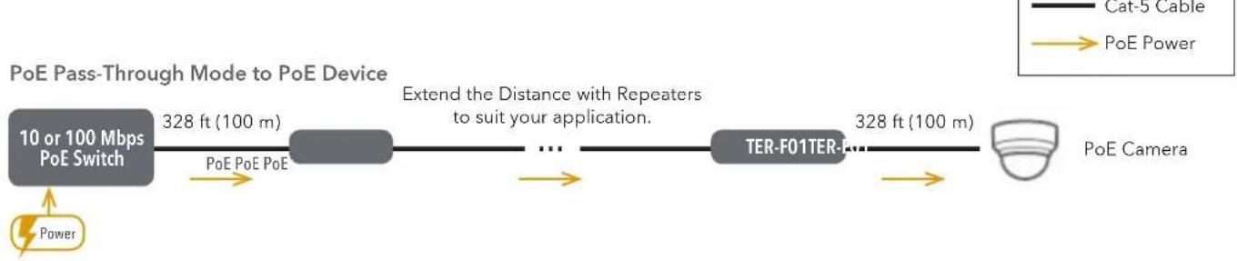
flowchart
graph LR
    A["10 or 100 Mbps PoE Switch"] -->|328 ft (100 m)| B["..."]
    B --> C["Extend the Distance with Repeaters to suit your application."]
    C --> D["TER-F01TER-F01"]
    D --> E["328 ft (100 m)"]
    E --> F["PoE Camera"]
    G["Power"] --> A
    H["Cat-5 Cable"] --> I["PoE Power"]
PoE Pass-Through Mode to Non-PoE Device
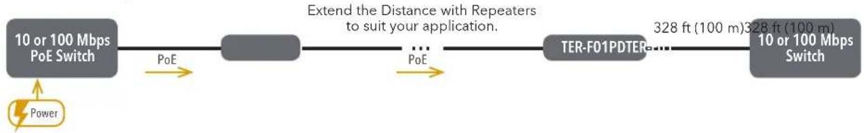
flowchart
graph LR
    A["10 or 100 Mbps PoE Switch"] -->|PoE| B["..."]
    B -->|PoE| C["TER-F01PDTER to 10 or 100 Mbps Switch"]
    C -->|328 ft (100 m) 328 ft (100 m)| D["End"]
    E["Power"] --> A
    F["Extend the Distance with Repeaters to suit your application."] --> B
High-Power PoE Pass-Through Mode to PoE+ Device
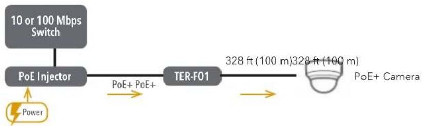
flowchart
graph LR
    A["10 or 100 Mbps Switch"] --> B["PoE Injector"]
    B --> C["TER-F01"]
    C --> D["328 ft (100 m)"]
    D --> E["PoE+ Camera"]
    F["Power"] --> B
    B -->|PoE+ PoE+| C

Low Power Consumption