SyncroIP DNB14TL2 - Security Camera Digimerge - Free user manual and instructions
Find the device manual for free SyncroIP DNB14TL2 Digimerge in PDF.


| Product Type | IR Vandal Dome IP Camera |
| Model | SyncroIP DNB14TL2 (also known as DNV14TL2) |
| Image Sensor | 1/2.5" CMOS Progressive Scan |
| Effective Pixels | 2.1 MP (1920 x 1080) |
| Minimum Illumination | Color: 0.1 lux @ F1.2; 0 lux with IR on |
| Lens | 2.8–12 mm Varifocal Megapixel lens |
| Horizontal Field of View | 79.3° – 29.8° |
| IR Night Vision Distance | 65 ft (20 m) |
| Day/Night | True Day/Night with ICR filter |
| Video Compression | H.264 High Profile, Main Profile, Baseline Profile; MJPEG |
| Maximum Resolution & Frame Rate | 1920x1080 @ 30 fps (stream1) |
| Triple Streaming | Yes: Stream1 (H.264), Stream2 (H.264), Stream3 (MJPEG) |
| Audio | Two-way audio (line in/out), G.711 A-Law/U-Law, RAW PCM |
| Network Interface | RJ45 10/100 Base-T with PoE (Class 3) |
| Power Supply | 12 V DC, 550 mA / 6.6 W; PoE 13 W max |
| Operating Temperature | -4°F to 122°F (-20°C to 50°C) |
| Ingress Protection | IP66 |
| Vandal Resistance | IK10 |
| Dimensions (Camera) | 5.1 x 4.4 in (130 x 112 mm) |
| Weight (Camera) | 1.87 lb (0.85 kg) |
| Mounting | 3-axis design for wall or ceiling; junction box compatible |
| Included Software | Milestone XProtect Go (8ch), Digimerge Syncro-V, CMS-DH PRO |
| ONVIF Compliance | ONVIF 2.1 (backward compatible to 1.02) |
| Mobile Apps | iPhone, iPad, Android |
| Storage Options | microSD (up to 64 GB), FTP, NAS |
| Certifications | CE, FCC, RoHS |
Frequently Asked Questions - SyncroIP DNB14TL2 Digimerge
User questions about SyncroIP DNB14TL2 Digimerge
0 question about this device. Answer the ones you know or ask your own.
Ask a new question about this device
Download the instructions for your Security Camera in PDF format for free! Find your manual SyncroIP DNB14TL2 - Digimerge and take your electronic device back in hand. On this page are published all the documents necessary for the use of your device. SyncroIP DNB14TL2 by Digimerge.
USER MANUAL SyncroIP DNB14TL2 Digimerge
DIG!MERGE | Right for Business
DNV14TL2
IR Vandal Dome IP Camera
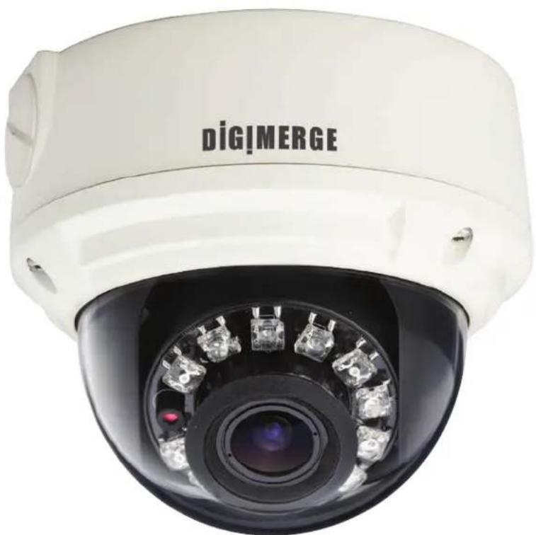
natural_image
Close-up of a white DigiMERGE security camera with visible lens and control buttons (no text beyond branding)Instruction Manual
English Version 1.0
www.digimerge.com
Copyright © 2012 Digimerge Technologies Inc.
Thank you for purchasing this product. Digimerge is committed to providing our customers with a high quality, reliable security solution.
This manual refers to the following models:
- DNV14TL2
For more information on this product, firmware updates, and accessory products, please visit us at:
www.digimerge.com

CAUTION
RISK OF ELECTRIC SHOCK DO NOT OPEN

CAUTION: TO REDUCE THE RISK OF ELECTRIC SHOCK DO NOT REMOVE COVER. NO USER SERVICABLE PARTS INSIDE.
REFER SERVICING TO QUALIFIED SERVICE PERSONNEL.

The lightning flash with arrowhead symbol, within an equilateral triangle, is intended to alert the user to the presence of uninsulated "dangerous voltage" within the product's enclosure that may be of sufficient magnitude to constitute a risk of electric shock.

The exclamation point within an equilateral triangle is intended to alert the user to the presence of important operating and maintenance (servicing) instructions in the literature accompanying the appliance.
WARNING: TO PREVENT FIRE OR SHOCK HAZARD, DO NOT EXPOSE THIS UNIT TO RAIN OR MOISTURE.
CAUTION: TO PREVENT ELECTRIC SHOCK, MATCH WIDE BLADE OF THE PLUG TO THE WIDE SLOT AND FULLY INSERT.
Important Safeguards
In addition to the careful attention devoted to quality standards in the manufacturing process of your video product, safety is a major factor in the design of every instrument. However, safety is your responsibility too. This sheet lists important information that will help to assure your enjoyment and proper use of the video product and accessory equipment. Please read them carefully before operating and using your video product.
Installation
- Read and Follow Instructions - All the safety and operating instructions should be read before the video product is operated. Follow all operating instructions.
- Retain Instructions - The safety and operating instructions should be retained for future reference.
- Heed Warnings - Comply with all warnings on the video product and in the operating instructions.
- Polarization - Do not defeat the safety purpose of the polarized or grounding-type plug.
A polarized plug has two blades with one wider than the other.
A grounding type plug has two blades and a third grounding prong.
The wide blade or the third prong are provided for your safety.

If the provided plug does not fit into your outlet, consult an electrician for replacement of the obsolete outlet.
- Power Sources - This video product should be operated only from the type of power source indicated on the marking label. If you are not sure of the type of power supply to your location, consult your video dealer or local power company. For video products intended to operate from battery power, or other sources, refer to the operating instructions.
- Overloading - Do not overload wall outlets of extension cords as this can result in the risk of fire or electric shock. Overloaded AC outlets, extension cords, frayed power cords, damaged or cracked wire insulation, and broken plugs are dangerous. They may result in a shock or fire hazard. Periodically examine the cord, and if its appearance indicates damage or deteriorated insulation, have it replaced by your service technician.
-
Power Cord Protection - Power supply cords should be routed so that they are not likely to be walked on or pinched by items placed upon or against them, paying particular attention to cords at plugs, convenience receptacles, and the point where they exit from the video product.
-
Ventilation - Slots and openings in the case are provided for ventilation to ensure reliable operation of the video product and to protect it from overheating. These openings must not be blocked or covered. The openings should never be blocked by placing the video equipment on a bed, sofa, rug, or other similar surface. This video product should never be placed near or over a radiator or heat register. This video product should not be placed in a built-in installation such as a bookcase or rack unless proper ventilation is provided or the video product manufacturer's instructions have been followed.
- Attachments - Do not use attachments unless recommended by the video product manufacturer as they may cause a hazard.
- Camera Extension Cables – Check the rating of your extension cable(s) to verify compliance with your local authority regulations prior to installation.
- Water and Moisture - Do not use this video product near water. For example, near a bath tub, wash bowl, kitchen sink or laundry tub, in a wet basement, near a swimming pool and the like. Caution: Maintain electrical safety. Powerline operated equipment or accessories connected to this unit should bear the UL listing mark of CSA certification mark on the accessory itself and should not be modified so as to defeat the safety features. This will help avoid any potential hazard from electrical shock or fire. If in doubt, contact qualified service personnel.
- Accessories - Do not place this video equipment on an unstable cart, stand, tripod, or table. The video equipment may fall, causing serious damage to the video product. Use this video product only with a cart, stand, tripod,
bracket, or table recommended by the manufacturer or sold with the video product. Any mounting of the product should follow the manufacturer's instructions and use a mounting accessory recommended by the manufacturer.

Service
- Servicing - Do not attempt to service this video equipment yourself as opening or removing covers may expose you to dangerous voltage or other hazards. Refer all servicing to qualified service personnel.
-
Conditions Requiring Service - Unplug this video product from the wall outlet and refer servicing to qualified service personnel under the following conditions:
-
When the power supply cord or plug is damaged.
- If liquid has been spilled or objects have fallen into the video product.
- If the video product has been exposed to rain or water.
- If the video product does not operate normally by following the operating instructions. Adjust only those controls that are covered by the operating instructions. Improper adjustment of other controls may result in damage and will often require extensive work by a qualified technician to restore the video product to its normal operation.
- If the video product has been dropped or the cabinet has been damaged.
-
When the video product exhibits a distinct change in performance. This indicates a need for service.
-
Replacement Parts - When replacement parts are required, have the service technician verify that the replacements used have the same safety characteristics as the original parts. Use of replacements specified by the video product manufacturer can prevent fire, electric shock or other hazards.
- Safety Check - Upon completion of any service or repairs to this video product, ask the service technician to perform safety checks recommended by the manufacturer to determine that the video product is in safe operating condition.
- Wall or Ceiling Mounting - The cameras provided should be mounted to a wall or ceiling only as instructed in this guide, using the provided mounting brackets.
- Heat - The product should be situated away from heat sources such as radiators, heat registers, stoves, or other products (including amplifiers) that produce heat.
G
Use
- Cleaning - Unplug the video product from the wall outlet before cleaning. Do not use liquid cleaners or aerosol cleaners. Use a damp cloth for cleaning.
- Product and Cart Combination - Video and cart combination should be moved with care. Quick stops, excessive force, and uneven surfaces may cause the video product and car combination to overturn.
- Object and Liquid Entry - Never push objects for any kind into this video product through openings as they may touch dangerous voltage points or "short-out" parts that could result in a fire or electric shock. Never spill liquid of any kind on the video product.
- Lightning - For added protection for this video product during a lightning storm, or when it is left unattended and unused for long periods of time, unplug it from the wall outlet and disconnect the antenna or cable system. This will prevent damage to the video product due to lightning and power line surges.
General Precautions
- All warnings and instructions in this manual should be followed.
- Remove the plug from the outlet before cleaning. Do not use liquid aerosol detergents. Use a water dampened cloth for cleaning.
- Keep enough space around the unit for ventilation. Slots and openings in the storage cabinet should not be blocked.
- During lightning storms, or when the unit is not used for a long time, disconnect the power supply, antenna, and cables to protect the unit from electrical surge.
FCC CLASS A NOTICE
NOTE
This equipment has been tested and found to comply with the limits for a Class A digital device pursuant to Part 15 of the FCC Rules. These limits are designed to provide reasonable protection against harmful interference when the equipment is operated in a commercial environment. This equipment generates, uses, and can radiate radio frequency energy and, if not installed and used in accordance with the manufacturer's instruction manual, may cause harmful interference with radio communications. Operation of this equipment in a residential area is likely to cause harmful interference, in which case you will be required to correct the interference at your own expense.
This equipment has been certified and found to comply with the limits regulated by FCC, EMC, and LVD. Therefore, it is designated to provide reasonable protection against interference and will not cause interference with other appliance usage.
However, it is imperative that the user follows the guidelines in this manual to avoid improper usage which may result in damage to the unit, electrical shock and fire hazard injury.
In order to improve the feature functions and quality of this product, the specifications are subject to change without notice from time to time.
DIGIMERGE
www.digimerge.com
Features

natural_image
Close-up of a white DIGMERGE surveillance camera with visible lens and control buttons (no text beyond branding)• 2.1 MP HD, 1/2.5" CMOS Progressive Scan
• 1080p picture quality at real-time (30 fps)
- Triple-streaming (H.264/MJPEG)
- Futureproof ONVIF 2.1 compliance (1.02 backwards compatible)
- Compatible with popular third party VMS software*
- Milestone XProtect® GO (8 Channel) VMS included plus Digimerge
• CMS-DH PRO and Syncro-V
• Power-over-Ethernet (PoE) operation, 14Watt max/12V operation
- Backup options: microSD card, FTP, NAS, local
- Mobile Apps: iPhone®, iPad®, Android™
• Supports two-way audio
• 2.8-12mm Varifocal MegaPixel lens
• 65ft (20m) IR Night Vision, True Day/Night (TDN)
• IP66 Weatherproof and IK10 Vandal Resistant
- Multi-browser support: IE, Firefox, Safari®, Chrome
• Free Digimerge DDNS service
• 3 Axis Design for wall/ceiling mount
* See www.digimerge.com for the most updated list of third party VMS compatibility
TABLE OF CONTENTS
1. Getting Started .... 1
1.1 Default Camera Username, Password, and Ports ..... 1
1.2 Camera Interior Overview 2
1.3 Mounting Accessories 3
1.4 ONVIF Compatibility and Included Software Overview 4
1.4.1 Milestone XProtect Go® 4
1.4.2 Syncro-V 5
1.4.3 CMS-DH PRO 5
2. Connection 6
3. Camera Installation.... 7
4. Junction Box Plate 12
4.1 Junction Box Plate Dimensions and Fitting 12
5. Junction Box Installation Types 13
5.1 Two Gang Fitting (Recommended) 13
5.2 4S Fitting 13
5.3 Octagon Fitting 13
6. Finding the Camera's IP Address 14
6.1 Finding the Camera's IP Address Using Syncro-V 14
6.2 Finding the Camera's IP Address using UPnP in Windows® 7 . . . . 15
6.3 Finding the Camera's IP Address using Bonjour® in Mac OS® . . . 16
6.4 Finding the Camera IP using the BNC Test Cable 17
7. Configuring Remote Connection 18
7.1 Connecting to a DDNS address using Syncro-V 22
8. Web Configuration 24
8.1 Supported Browsers 24
8.2 Chrome, Firefox, and Safari Setup 24
8.3 Internet Explorer® Setup 25
8.4 Web Interface/Live Video Overview 28
8.4.1 Live Video Menu 28
8.4.2 Configuring Camera Settings 29
8.5 Device Info 30
8.6 Stream Configuration 31
8.7 Device Configuration 32
8.7.1 Local Network 33
8.7.2 Device Port 34
8.7.3 Camera 35
8.7.4 Date & Time 35
8.7.5 OSD 37
8.7.6 Microphone 38
8.7.7 BNC Video Output 39
8.7.8 Language 39
8.8 Alarm Configuration 40
8.8.1 Disk Alarm 40
8.8.2 Motion Alarm 41
8.9 Local Record 43
8.9.1 Record Directory 43
8.9.2 Record Policy 48
8.10 Privacy Masking 50
8.11 Network Service 50
8.11.1 DDNS 51
8.12 Service Center 51
8.12.1 SMTP (Email Alert Setup) 52
8.13 Privilege Manager 53
8.13.1 Group 53
8.13.2 User 55
8.13.3 Unlocking User Accounts 56
8.14 Protocol 56
8.14.1 Protocol 57
8.15 Device Restart 57
8.16 Default Settings 57
8.17 Sensor Configuration 58
8.17.1 Image Adjust 59
8.17.2 Shutter Control 59
8.17.3 Gain Mode 60
8.17.4 Day/Night Mode 60
8.17.5 Auto Iris 61
8.17.6 Gamma 61
8.17.7 AE Meter Mode 62
8.17.8 WDR 62
8.17.9 WB Setting 63
8.17.10 Mirror 64
8.17.11 Noise Filter 64
-
Resetting to Factory Defaults 65
-
Dimensions 67
- Technical Specifications.... 68
- Troubleshooting 69
1. GETTING STARTED
The system comes with the following components:
- 1 x Camera
- 6 x Camera locking screws (3x inside camera; 3x spare)
- 1 x Surface mounting template
- 1 x Junction box plate and screw kit
- 1 x Mounting screw kit
- 1 x Allen key
- 1 x Conduit key
- 1 x RJ45 coupler
- 1 x BNC test cable
- 1 x Instruction Manual
- 1 x Quick Start Guide
- 1 x Software/Documentation CD
1.1 Default Camera Username, Password, and Ports
Username: admin
Password: admin
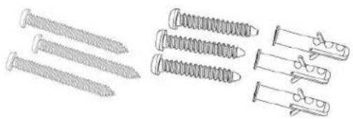
natural_image
Illustration of various screw and nut components (no text or symbols)Mounting Screw Kit:
- 3 x 2.8in / 70mm screws
- 3 x 1.2in / 30mm screws
- 3 x 1.6in / 40mm anchors
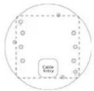
Junction Box Plate
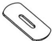
Conduit Key
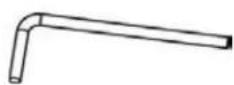
Allen Key

RJ45 Coupler
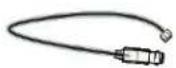
BNC Test Cable
Ports: 80 (HTTP), 30001 (Control/Streaming), 8080 (RTMP), 554 (RTSP)
IP Address: DHCP Enabled by Default (Router will automatically assign IP address)
NOTE: Once you have completed the basic setup of the camera, it is recommended to configure a static IP address. This will prevent the camera IP address changing in the event of a power failure. For details, see "8.7.1 Local Network" on page 33.
1.2 Camera Interior Overview
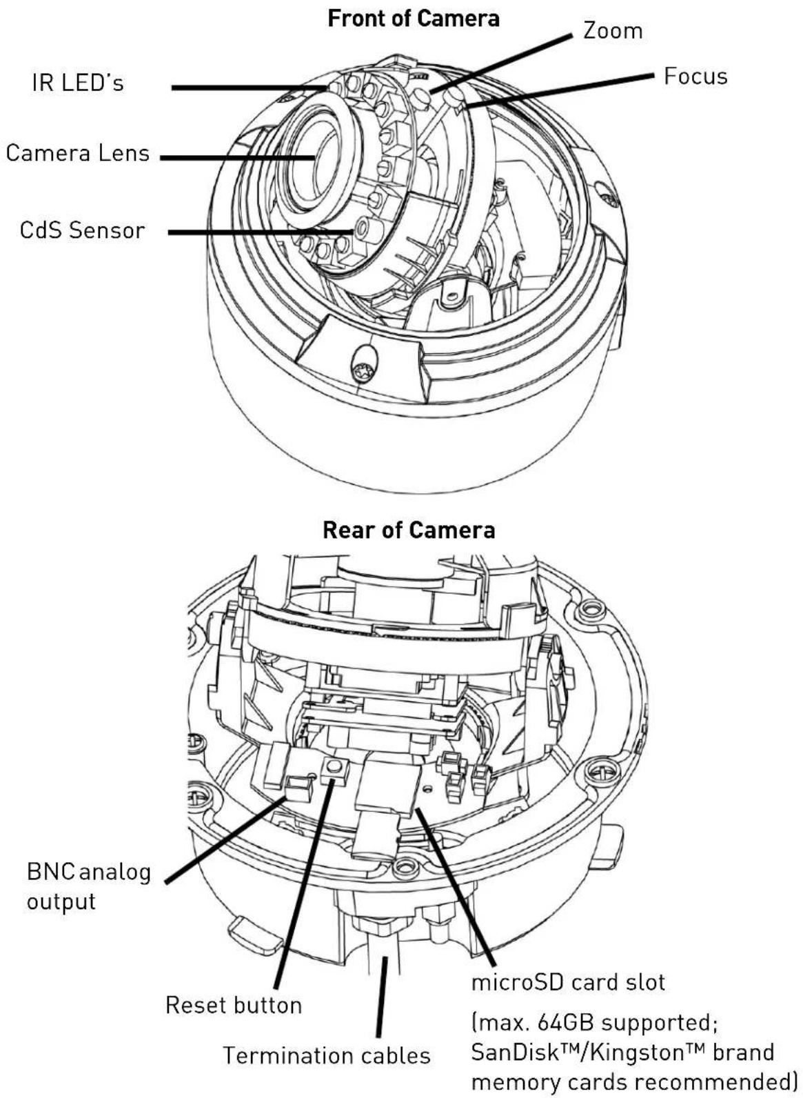
1.3 Mounting Accessories
For more information or accessory installation instructions, visit www.digimerge.com

natural_image
Line drawing of a mechanical device with a curved handle and circular base (no text or symbols)Wall Mount - model # MNTV2XW

natural_image
Technical line drawing of a mechanical component with a flanged base and circular housing (no text or symbols)Pendant Mount - model # MNTV2XC
natural_image
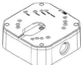
Technical line drawing of a square electronic device with mounting holes and a central port (no text or symbols)Junction Box Mount - model # MNTV2XB
Can also mount MNTV2XC or MNTV2XW.
natural_image
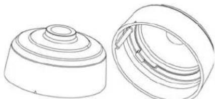
Technical line drawing of two views of a mechanical component (no text or symbols)Pendant Cap - model # MNTV2XPC
Replaces the need for the camera base. Compatible with ceiling conduit installations.

natural_image
Technical line drawing of a metal bracket with mounting holes and a central circular cutout (no text or symbols)Corner Mount bracket - model # MNTV2XR
Can fit either MNTV2XW or MNTV2XJ.

natural_image
Pure mechanical diagram showing a bracket with a circular hole and mounting holes, no text or symbols present.Pole Mount - model # MNTV2XP
Can fit either MNTV2XW or MNTV2XJ.

natural_image
Technical line drawing of a mechanical housing or enclosure with mounting flanges and central bore (no text or symbols)Junction Box Attachment for MNTV2XW & MNTV2XC-model # MNTV2XJ
Fits either wall mount and ceiling mount. Symmetrical design - reversible for top or bottom conduit.
1.4 ONVIF Compatibility and Included Software Overview
This camera is ONVIF v2.1 compliant. It is designed for interoperability with popular VMS's and NVR's*, with backwards compatibility to ONVIF v.1.02. For more information on ONVIF, visit www.onvif.org
Milestone XProtect Go®, Digimerge Syncro-V, and Digimerge CMS-DH PRO are provided. Milestone XProtect Go® provides a server solution that can host multiple cameras on a centralized location for access by remote clients. Syncro-V and CMS-DH PRO are client-only, meaning that each camera must be individually configured for remote access.
NOTE: Provided software is PC compatible only; Mac OS® access to the cameras is available via Safari® browser only.
Please see the Quick Start Guide or the documentation provided on the CD for detailed software instructions. This manual only covers hardware installation, network setup, and web browser configuration.
1.4.1 Milestone XProtect Go®
- Milestone XProtect® Go is a fully-featured client/server solution providing mobile applications and remote access capabilities.
- Milestone XProtect® Go is free and requires a one-time annual registration. Each year, you must renew your registration to continue using Milestone XProtect® Go. Re-registration is also free.
- To view your installation from a smartphone or tablet, you can install the free Milestone Mobile Server component and XProtect® Mobile (available as a free download on the App Store ^SM and Google Play).
- Milestone XProtect® Go supports up to eight IP cameras. Upgrade options are available from Milestone.
- To upgrade your Milestone XProtect® software version, visit: www.milestonesys.com/productoverview
- For Milestone XProtect® Go documentation and technical support, visit: www.milestonesys.com/go/support
1.4.2 Syncro-V
- Digimerge Syncro-V is a client-only solution that supports up to 36 IP cameras. Syncro-V is a free software provided on the CD.
- Syncro-V supports all the features of the camera. It can access microSD/SD card recordings and camera setup over a local network.
- Syncro-V manual is provided on the CD. For Syncro-V support, visit www.digimerge.com
1.4.3 CMS-DH PRO
- Digimerge CMS-DH PRO is a client-only solution that supports up to 16 IP cameras. CMS-DH PRO is a free software available on www.digimerge.com
- CMS-DH PRO allows you to view IP cameras and analog cameras from your Touch Series DVR's side-by-side via the virtual DVR feature. You can view up to 64 screens at a time, including up to 16 IP cameras.
- CMS-DHS PRO does not support all the features of the camera, such as microSD/SD card recording.
• CMS-DH PRO manual and support are available from www.digimerge.com
2. CONNECTION
The camera has the following termination cables:

- RJ45 Network Interface: Connect to a router or switch on your network using RJ45 Ethernet cable (Cat5e or better). 100Mhz connection. PoE supported (class 3 PoE switch required).
NOTE: Use the included RJ45 coupler to connect to male end of RJ45 Ethernet cable.

RJ45 Coupler
- Audio Input (RCA): Connect to a self-powered microphone for listen-in audio.
- Audio Output (RCA): Connect to an amplifier or self-powered speaker for intercom/2-way audio.
- DC12V (1A): 12V DC power input terminal. Make sure to follow correct polarity (+/-) marked on the power connector when connecting to power.
• Minimum Power Requirement: 550mA / 6.6W.
3. CAMERA INSTALLATION

Make sure to follow the correct polarity if connecting the camera to DC power. Polarity is marked on the power connector.

natural_image
Technical line drawing of a mechanical component with layered structure and mounting bracket (no text or symbols)All Installation Methods
- Loosen the three tamper screws using the provided allen key. Lift the dome cover.
NOTE: If you plan to use conduit fitting, remove conduit cap using the provided conduit key.


natural_image
Technical line drawing of a mechanical assembly with screws and bearing housing (no text or symbols)Method 1 - Direct Attach Install
2a. Use the included mounting template (Installation Option 2) to mark and pre-drill the required holes.
Remove 2 of the 3 base locking screws. Use 2pc of the 2.8" screws to mount the camera directly to the mounting surface.
Remove the 3rd base locking screw and install the 3rd 2.8" screw.
Go to step 4 to complete installation.
Method 2 - Camera Base Install
2b. Use the included mounting template (Installation Option 1) to mark and pre-drill the required holes.
natural_image
Line drawing of a hand using a drill pen to lift a circular mechanical component (no text or symbols)
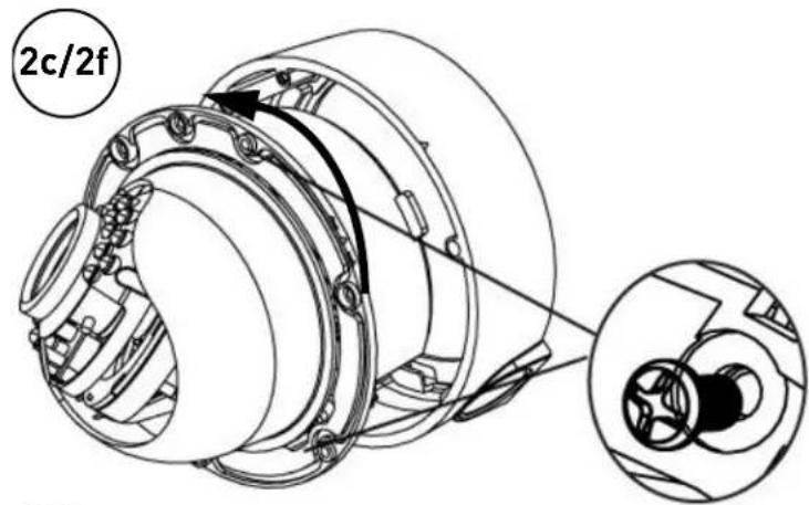
2c. Remove the camera base by unscrewing the 3 base locking screws, and turn camera module approx. 5 degrees counterclockwise to detach camera base from the camera module.
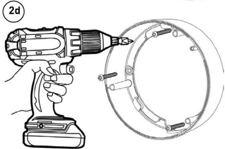
2d. Install the base to the correct holes as indicated on the mount template using the 1.2" screws.
Go to step 3a to complete installation.
Method 3 - Junction Box Install
2e. Attach provided fitting plate to junction box (see "5. Junction Box Installation Types" on page 13).
2f. Remove the camera base by unscrewing the 3 base locking screws, and turn the camera module approx. 5 degrees counterclockwise to detach camera base from camera module.
2g. Install the base to the junction box plate using the base fitting screws.
Go to step 3a to complete installation.
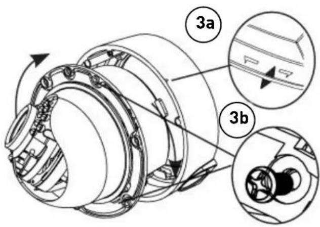
Reattaching the Camera Module
3a. Reinsert camera module into camera base by aligning the arrow notches on the edge of the camera module and the camera base (label on edge of camera module indicates the location of the arrow notch), and turning camera module clockwise to lock into place.
3b. Use the 3 base locking screws to secure camera base to camera module.
Go to step 4 to complete installation.

- Remove camera cover by squeezing the back and front of the cover (as indicated by the arrow indicators) at the same time and lifting it up and away from the lens.
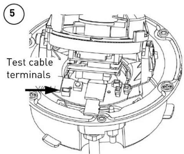
- Insert a video test cable into the video test cable terminals and connect to a test monitor to set up camera.

Video Test Cable

natural_image
Technical line drawing of a mechanical component with no visible text or symbolsThumb Screw
6a. Adjust camera viewing angle and secure into place by tightening thumb screw using a flat head screwdriver.

Avoid pointing the camera lens in angles where the IR LEDs are blocked by the camera cover or dome cover. If IR LEDs are blocked, it may result in an unclear nighttime image.


microSD card
6b. Adjust zoom and focus as required.
NOTE: Lens adjustment levers are by default in the locked position. Turn counterclockwise to unlock. Tighten levers to secure lens setting.
6c. (Optional) Insert a microSD card into the camera. To enable recording, you must format the microSD card and configure microSD recording (see "8.9.1 Record Directory" on page 43).
NOTE: The camera supports microSD cards up to a maximum size of 64GB. SanDisk™ or Kingston™ brand microSD cards are recommended.
6d. Re-attach the camera cover, using the thumb screw as a guide, until it snaps into place.


Arrow on camera base Arrow on camera module (inside camera)
Arrow on dome cover
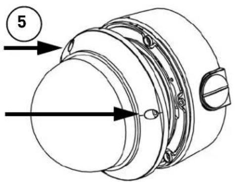
- Re-attach the dome cover. Align the arrows as shown in the diagram to ensure a waterproof seal. Use the allen key to tighten the tamper screws.
NOTE: Make sure dome cover cord does not get caught in the rubber seal.
Correct Arrow Alignment
4. JUNCTION BOX PLATE
Junction box plate is used to install camera into standard 4S and Octagon junction boxes. Junction box plate screw kit contains the following accessories:
- 3 x Base fitting screws (PWM3 Type)
- 4 x 2S / 4S plate screws (KM3.5 Type)
- 2 x Octagon fitting screws (KM4 Type)

Base Fitting Screw

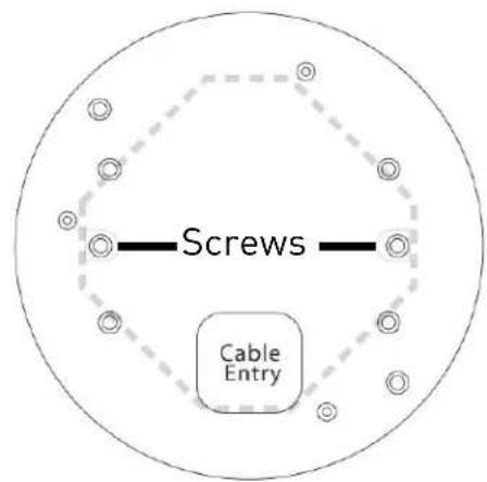
natural_image
Line drawing of a threaded screw with a flanged head (no text or symbols)Octagon Screw

natural_image
Line drawing of a threaded screw with no text or symbols2S / 4S Screw
4.1 Junction Box Plate Dimensions and Fitting
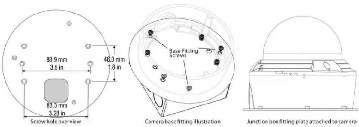
5. JUNCTION BOX INSTALLATION TYPES
5.1 Two Gang Fitting (Recommended)
Two gang fitting requires 4x 2S/4S screws.
NOTE: Two gang fitting provides the most robust installation.
5.2 4S Fitting
4S fitting requires 2x 2S/4S screws.
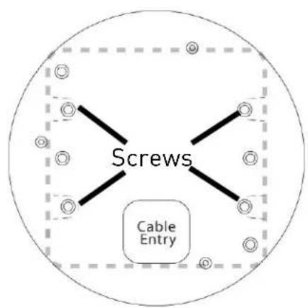

5.3 Octagon Fitting
A 4" Octagon fitting requires 2x Octagon screws.
NOTE: Screws used for the octagon fitting are larger compared to those used for the 2S/4S (M4 type).
6. FINDING THE CAMERA'S IP ADDRESS
Use the steps below to find the camera's IP address and connect to the camera over the local area network (LAN) using Syncro-V, UPnP on Windows® 7, or Bonjour® in Mac OS®.
6.1 Finding the Camera's IP Address Using Syncro-V
- Install Syncro-V from the CD or from www.digimerge.com. Double-click
the Syncro-V icon (V) on the Desktop. The log in screen appears.
- Under User Name and Password, enter the default Syncro-V user name (admin) and password (admin). Click Login.

- Syncr o-V opens and scans the local network for connected cameras. Detected camera IP addresses on the LAN appear in the Device List on the left side of the screen with a icon.

-
Click on a camera IP address in Device List to login.
-
Under User Name, enter the user name for the camera (default: admin). Under Password, enter the password for the camera (default: admin). Click Continue.

- The camera appears under the camera IP address. Click and drag the camera to the display grid to open it.

NOTE: For detailed instructions on using Syncro-V, see the Syncro-V manual on the CD.
6.2 Finding the Camera's IP Address using UPnP in Windows® 7
NOTE: To use this method, your router must support UPnP and the camera and computer must be on the same network. UPnP is enabled in the camera by default, and can be enabled/disabled using Syncro-V(check the Syncro-V manual for details).
- Click Start→Computer→Network. The camera's IP address appears under Network Infrastructure.
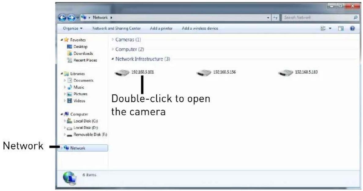
- Doubl e-click the camera to open it in your default browser.
- Under User Name and Password, enter the camera's User Name (default: admin) and Password (default: admin) and click Login.

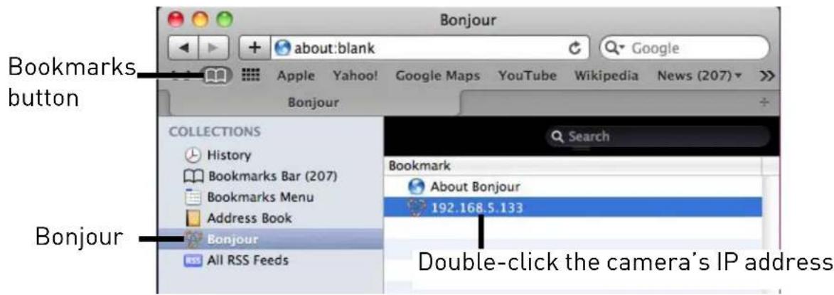
6.3 Finding the Camera's IP Address using Bonjour® in Mac OS®
NOTE: To use this method, the camera and computer must be on the same network. Bonjour® is enabled by default, and can be enabled/disabled using Syncro-V (check the Syncro-V manual for details).
-
Op en Safari® browser and click the Bookmarks button ( ).
-
Click Bonjour. The camera's IP address appears in the Bonjour Devices list.
- Doubl e-click the camera to open it in Safari®.
- Under User Name and Password, enter the camera's User Name (default: admin) and Password (default: admin) and click Login.

6.4 Finding the Camera IP using the BNC Test Cable
When the BNC test cable is connected to the camera, the IP address is shown on the test monitor. The camera must be connected to power to use the BNC test cable.
NOTE: The default IP address of 192.168.0.120 is shown if the camera cannot obtain an IP address from the router. Check the Ethernet/power connections and router configuration.
7. CONFIGURING REMOTE CONNECTION
Follow the steps below to configure your camera for connections over the Internet using a web browser, Syncro-V, or other VMS software.
Step 1 of 6: Locate the camera's local IP address:
- See "6. Finding the Camera's IP Address" on page 14.
Step 2 of 6: Port Forward your router:
You need to enable port forwarding for the following ports on your router to the camera's local IP address:
- HTTP Port (default: 80)
• Control Port (default: 30001)
NOTE: If you are configuring multiple IP cameras for individual remote access, you must change the ports for each camera. Two cameras cannot use the same port number.
NOTE: Port forwarding the RTSP and RTMP ports is not necessary unless your installation has special requirements.
There are two methods for port forwarding:
- You can manually port forward your router. See your router's user manual for details. An example of a port forwarding screen is shown below.
| Port Range | |||||
| Application | Start | End | Protocol | IP Address | Enable |
| HTTP | 80 to | 80 | Both | 192.168.1. 100 | |
| Control | 30001 to | 30001 | Both | 192.168.1. 100 | |
- Or, you can use the Digimerge Auto Port Forwarding Wizard provided on the CD to automatically configure the necessary ports. See the Auto Port Forwarding manual on the CD for details.
Step 3 of 6: Locate your camera's MAC address:
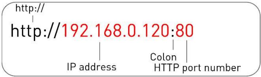
- Open a web browser and enter the camera's IP address in the address bar in the following format:
-
Under User Name and Password, enter the camera's User Name (default: admin) and Password (default: admin) and click Login.
-
Click Device Info and write down the MAC Address.

Note: The device ID is unique. Please don't change it unless special requirement.
Step 4 of 6: Register for Digimerge DDNS:
Digimerge offers a free DDNS service for use with your IP camera. A DDNS account allows you to set up a web site address that points back to your local network. The following outlines how to set up your free DDNS account.
NOTE: Your router must support UPnP to enable DDNS.
NOTE: You may use the same DDNS account for multiple IP cameras on the same LAN.
To setup your free Digimerge DDNS account:
- In your browser, go to http://ddns.digimerge.net and click Create Account.
- Complete the Account Information fields with your personal information.
Digimerge

Click Create Account

-
Complete the System Information fields:
-
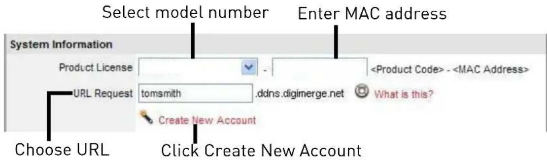
Product License: Select your product model from the Product License drop down menu.
- ←Product Code→ - ←MAC Address→: Enter the camera's MAC address you recorded earlier.
- URL Request: Choose a URL for your DDNS connection (i.e. your name, your company or business name, or anything of your choice).
-
Once the information has been entered, click Create New Account.
-
Your Account information will be sent to you at the email address you used in Step 2. Record your Account Information below.
Domain Name:
User Name:
Password:
Step 5 of 6: Enable DDNS on the camera:
- Enter the camera's IP address in your web browser. Log in and then click Network Service→DDNS.
- Check Enable DDNS.
-
Configure the following:
-
Provider: Select digimerge_ddns.
- Domain Name: Enter the Domain Name you received from the confirmation email you received after you created your DDNS account (e.g. tomsmith.digimerge.net).
- User Name: Enter the User Name you received in the confirmation email.
-
Password: Enter the Password you received in the confirmation email.
-
Click OK to save settings.
Step 6 of 6: Connect to the camera's DDNS address:
- Enter the camera's DDNS address in your web browser in the following format:

- Under User Name and Password, enter the camera's User Name (default: admin) and Password (default: admin) and click Login.
Once you have logged into your system using your DDNS address, you can connect to the IP camera from a remote location using a web browser, Syncro-V, or other VMS software.
7.1 Connecting to a DDNS address using Syncro-V
NOTE: Complete all the steps above before performing the following method.
- Open Syncro-V and click Device Manager→Video Device Manager.
- Click Manager. The Device Maintenance window opens.
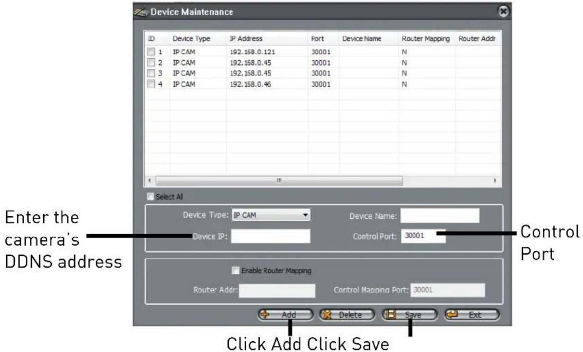
- Under De vice IP, enter the Domain Name from the confirmation email. For example, enter tomsmith.digimerge.net.
- Under Contr ol Port, enter the camera's control port (default: 30001).
- (Optional) Under Device Name, enter a name for the camera.
- Click Add to add the camera to the Device List.
-
Click Save to save changes. Click OK.
-
Close Device Maintenance and Device Manager, and return to the Live Video screen. The newly added camera will appear in Device List.

NOTE: A icon is shown for all cameras outside of the LAN. This does not affect your ability to connect to the camera remotely.
- Click on the camera in Device List to login. Enter the User Name (default: admin) and Password (default: admin) and then click Continue.

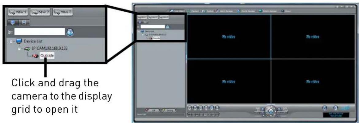
- Click and drag the camera to a display grid screen to open it.
NOTE: For detailed instructions on using Syncro-V, see the Syncro-V manual on the CD.
The camera includes a built-in web interface that can be accessed using a web browser.
8.1 Supported Browsers
- Google Chrome, Mozilla Firefox, and Apple Safari® (via Adobe Flash Player)
- Microsoft Internet Explorer® 7.0 or later, 32-bit version (via ActiveX®)
8.2 Chrome, Firefox, and Safari Setup
- Connect the camera to your local network and find the camera's IP address. See "6. Finding the Camera's IP Address" on page 14.
- Open your browser and enter the camera's IP address in the address bar in the following format:

NOTE: You can also connect to the camera using a DDNS address (DDNS setup and port forwarding required; see "7. Configuring Remote Connection" on page 18 for details).
- Under User Name and Password, enter the camera's User Name (default: admin) and Password (default: admin) and click Login.

- The main screen for the camera web interface opens. From here you can view and configure the camera.
NOTE: If you do not see video from the camera, make sure your computer has the latest version of Adobe Flash Player installed (visit http://www.adobe.com/ to download the latest version). After installing Flash Player, restart your browser and reconnect to the camera.
8.3 Internet Explorer® Setup
Step 1 of 2: Change Internet Explorer security settings for ActiveX®:
-
Open Internet Explorer and open the Security tab.
-
Internet Explorer 8: Click Tools → Internet Options and select the Security tab.
-
Internet Explorer 9: Click → Internet Options and select the Security tab.
-
Click Custom Level.

- Under Download unsigned ActiveX controls, click Prompt (recommended) or Enable.
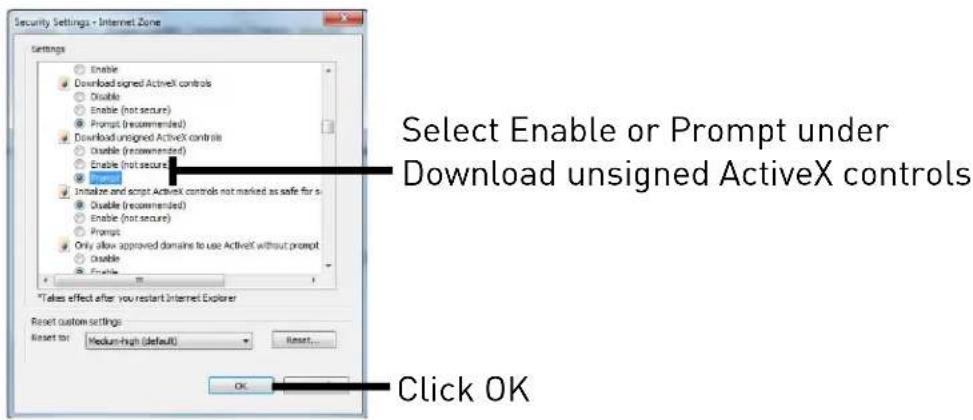
- Click OK. Click OK again to save changes.
Step 2 of 2: Log into camera:
- Connect the camera to your local network and find the camera's IP address. See "6. Finding the Camera's IP Address" on page 14.
- Enter the camera's IP address in the address bar in the following format:

NOTE: You can also connect to the camera using a DDNS address (DDNS setup and port forwarding required; see "7. Configuring Remote Connection" on page 18 for details).
- Under User Name and Password, enter the camera's User Name (default: admin) and Password (default: admin) and click Login.

- If your computer has Flash Player installed, the main screen for the camera web interface opens. From here you can view and configure the camera.
NOTE: The ActiveX plug-in may provide smoother video performance than Flash Player. To use ActiveX, click the message above the video window. Then click inside the video area, select Install this Add-on for all users on this computer, and follow the prompts.
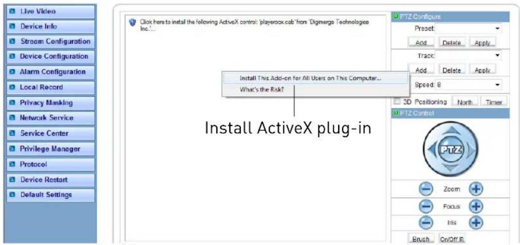
NOTE: If your computer does not have Flash Player installed, you will be prompted to select if you would like to use ActiveX or Flash Player to connect to the camera:
- Click to play live video with ActiveX control to reduce latency (recommended): Uses an ActiveX plug-in to connect to the camera. To install the plug-in, click on the video area, and select Install this Add-on for all users on this computer, and follow the prompts.
- Click to download the latest version of Flash Player to play live video: Opens a link to download Flash Player from Adobe's website. After completing the installation, restart your browser and reconnect to the camera.

8.4 Web Interface/Live Video Overview
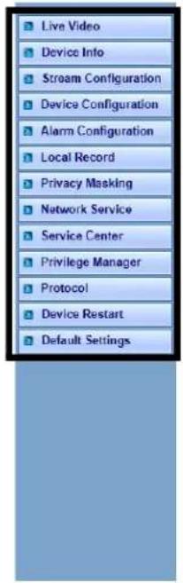
Camera configuration menus
Click and drag to zoom in. Right-click and select ZoomOut to zoom out.
Double-click inside window for full-screen

Select Stream
TIP: Select stream2 for better performance for remote connections. Stream2 has a lower resolution than stream1.
The Live video page appears when you log into the camera. Live video requires ActiveX® plugins or Adobe Flash Player.
8.4.1 Live Video Menu
You can right-click on the live video area to bring up the Live Video Menu.
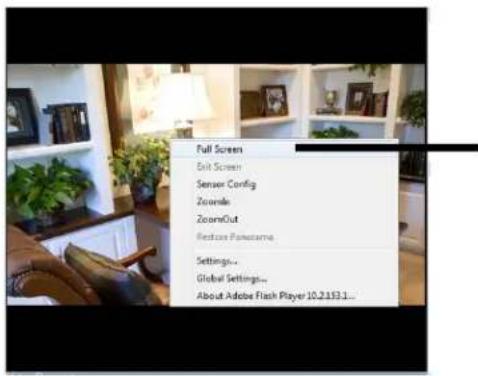
Right-click on the video area to open the Live Video Menu
The Live Video Menu contains the following options:
• Full Screen: Open the video in full screen. Press ESC to exit full screen.
- Sensor Config: Configure the camera sensor settings. See "8.17 Sensor Configuration" on page 58.
- ZoomIn: Zoom in one level.
- ZoomOut: Zoom out one level.
- Restore Panorama: Zoom out all the way.
8.4.2 Configuring Camera Settings
- Click the options on the left to configure camera settings. Setting options are detailed in the remainder of this section.
Click to select camera menus


natural_image
Interior view of a modern office with wooden furniture, framed pictures, and plants (no visible text or symbols)
TIP: Some sub-menus have a Reset button. This button will reset the sub-menu options to factory defaults. You then have to click OK to save changes.
8.5 Device Info

Note: The device ID is unique. Please don't change it unless special requirement.
The Device Info page shows information about your IP camera, such as the Device Name (which appears in the Device List in Syncro-V), firmware version, MAC address, and camera inputs and outputs. You can also configure the Device Name for your camera.
ATTENTION: The device ID is unique. Do not change it unless your installation has special requirements.
To configure the Device Name:
- Click Device Info.
- Under De vice Name, enter the desired device name and then click Set.
8.6 Stream Configuration

The Stream Configuration page allows you to configure the camera's video streams. The camera supports three different video streams. This allows you to have a high quality recording stream (stream1), a lower quality stream (stream2) to preserve bandwidth for remote connections, and an MJPEG stream for applications requiring MJPEG.
To configure video streaming settings:
- Click Stream Configuration. Under Stream ID, select the stream you would like to configure.
- Configure the following:
• Video Encode Type: Select the Video Encoding type for the stream. Stream1 and stream2 can be configured for H.264 High Profile, H.264 Main Profile, or H.264 Base Profile. Stream3 supports MJPEG only.
- Audio Encode Type: Select the Audio Encoding type for the stream: G711_ALAW, G711_ULAW, or RAW_PCM.
- Resolution: Select the resolution for the stream. Stream1 and stream3 can be set to 1920x1080 or 640x360. Stream2 can only be set to 640x360.
- Frame Rate: Select the frame rate for the stream up to maximum of 30FPS for stream1 or stream2 or 12FPS for stream3.
NOTE: Frame rate may be automatically adjusted to account for bandwidth limitations.
- I Frame interval: Select the interval for I frames: 1, 2, or 3. The default value of 2 should be used unless there are special requirements. The I Frame interval does not apply to stream3.
- Bit Rate: For stream1 or stream2, select CBR (Constant Bit Rate) or VBR (Variable Bit Rate). Enter the desired bit rate below in kbps. Stream3 only supports VBR.
• Quality: Select the video quality between 1 (lowest) and 9 (highest).
TIP: A quality of 7 provides a good picture. It is not recommended to set a high quality value with a small VBR bit rate.
- Click OK to apply changes.
8.7 Device Configuration
Device Configuration contains the following sub-menus:
- Local Network
- Device Port
- Camera
- Date and Time
- OSD
- Microphone
- BNC Video Output
- Language
- Multicast (Not supported)
• Dome PTZ (Not supported)
8.7.1 Local Network

The Local Network page shows the camera's current IP address and network parameters if DHCP is enabled. It also allows you to set a static IP address for the camera (see below), set the networking parameters, and to select IPv4 or IPv6.
NOTE: DHCP is enabled by default. When DHCP is enabled, the IP address is shown under DHCP IP. Once you have completed the basic setup of the camera, it is recommended to configure a static IP address. This will prevent the camera IP address changing in the event of a power failure.
To configure the camera's networking parameters:
- Click Device Configuration→Local Network.
- Under IP Protocol, select IPv4 or IPv6. If you would like to use IPv6, make sure it is supported on your network. You may need to contact your network administrator or ISP for details.
-
Select Device obtain an IP address automatically to use DHCP or Device use the following IP address to set a static IP address for the camera. If you are using a static IP address, configure the following:
-
IP Address: Enter the IP address you would like to assign to the camera. Make sure the IP address is available on your network.
- Subnet Mask: Enter the subnet mask.
-
Preferred DNS Server/Alternate DNS Server: Enter desired DNS servers.
-
Click OK to save changes. The camera will restart with the new IP address.
8.7.2 Device Port
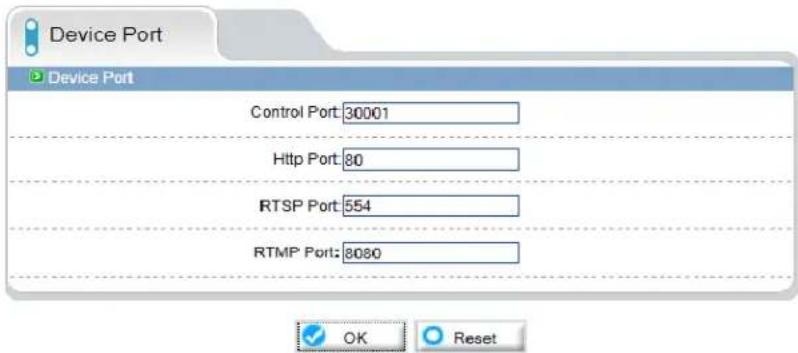
The Device Port page (Device Configuration→Device Port) allows you to configure the camera's port configuration. The camera has the following ports:
- Control port: The default is 30001. Enables video streaming.
- HTTP Port: The default is 80. Enables web access. Please note that if the HTTP is port is anything other than 80, you must enter http:// before the camera's IP address and colon (:) and the HTTP port after the IP address when connecting using an Internet browser (e.g. if the HTTP port is 85, enter http://192.168.x.x:85).
- RTSP Port: Default is 554. Only used for special applications requiring RTSP streaming.
- RTMP Port: Default is 8080. Only used for special applications.
NOTE: If you are configuring multiple IP cameras for individual remote access (without an NVR or server), you must change all the ports for each camera. Two cameras cannot use the same port number.
To change camera ports:
- Click Device Configuration→Device Port.
- Configure the camera ports as required and then click OK.
8.7.3 Camera
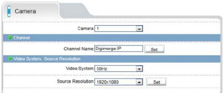
The Camera page (Device Configuration→Camera) allows you to configure the Channel Name, which appears on the camera OSD and the video system frequency.
To change the Channel Name:
- Configure the Channel Name as needed and then click the Set button next to Channel Name.
To change the video system frequency:
- Select the desired setting under Video System and then click the Set button next to Source Resolution.
8.7.4 Date & Time

The Date & Time page allows you to configure the camera's date and time.
You can set the camera's date and time the following ways:
• Using an NTP server (recommended)
- Using your computer's system time
- Manually

The camera is configured to use NTP by default, but you must set the time zone and Daylight Savings Time settings to ensure accurate time. After a power failure, the camera is configured to connect to an NTP server and automatically update the time when power is restored. If using another method to set the camera clock, time must be manually updated after a power failure.
To set the camera's date and time using an NTP server:
- Click Device Configuration→Date & Time.
- Under Time Zone, select your time zone.
- If y our region observes daylight savings time, check Adjust clock for daylight saving changes.
-
Under Start and End, select the start and end times for daylight savings.
-
Next to Current PC Time, click Apply.
To sync the camera's date and time to your computer's system time:
- Click Device Configuration→Date & Time.
- Un-check Enable NTP and click Apply at the bottom of the screen.
- Under Time Zone, select your time zone.
- If your region observes daylight savings time, check Adjust clock for daylight saving changes.
- Under Start and End, select the start and end times for daylight savings.
- Click Apply next to Current Computer Time. The Current Device Time updates.
To set the camera's date and time manually:
- Click Device Configuration→Date & Time.
-
Under Time Zone, select your time zone.
-
Un-check Enable NTP and click Apply at the bottom of the screen.
- If your region observes daylight savings time, check Adjust clock for daylight saving changes.
- Under Start and End, select the start and end times for daylight savings.
- Click Set Manually, and use the on-screen calendar to set the time and date.
- Click Apply. The camera updates to the newly entered time.
8.7.5 OSD
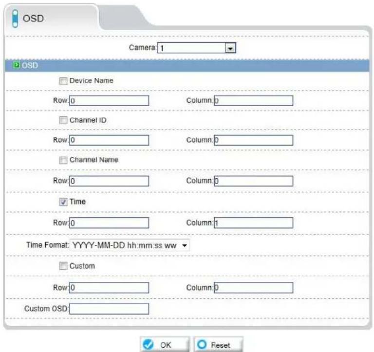
The OSD page allows you to configure the camera's on-screen display text.
To configure the camera OSD:
- Click Device Configuration→OSD.
- Check the following options to enable OSD text:
• Device Name: Display the Device Name.
- Channel ID: Show the channel ID number.
- Channel Name: Show the name of the channel set in the Camera menu.
- Time: Show the date and time on the OSD. Select the desired date and time format under Time Format.
- Custom: Create a custom OSD message. Enter the custom OSD text under Custom OSD.
Device Name —— Digimerge IP Camera
Channel ID —— ch1
Channel Name —— dome
Time —— 15:01:47 2012-05-28 Mon
Custom —— custom OSD message
- Enter the desired Row and Column for enabled OSD messages. Text on row 0 is shown at the top of the screen, and moves down as the row number increases. Text on column 0 is shown on the left side of the screen, and moves right as the column number increases.

- Click OK to update the camera OSD.
8.7.6 Microphone
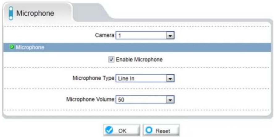
Configure microphone settings for listen-in audio. Self-powered microphone required (not included).
To configure microphone settings:
- Click Device Configuration→Microphone.
- Check Enabl e Microphone to enable listen-in audio or un-check to disable.
- Under Micr ophone Volume, select the volume for the microphone between 1\~100.
- Click OK to save changes.
8.7.7 BNC Video Output

Under BNC Output (Device Configuration→BNC Output), select On to enable analog output or Off to disable and click OK.
8.7.8 Language

Change the language for the camera OSD display (e.g. time and date display) and email alarms. Supported languages are English, Polish, Russian, and Chinese.
To change the language for the OSD and email alarms:
- Click Device Configuration→Language.
- Under Language, select the desired language then click OK to save changes.
8.8 Alarm Configuration
Alarm Configuration contains the following sub-menus:
- Disk Alarm
- Motion Alarm
- Alarm I/O (Not supported)
- I/O Alarm Linkage (Not supported)
- Alarm Setting (Not supported)
8.8.1 Disk Alarm
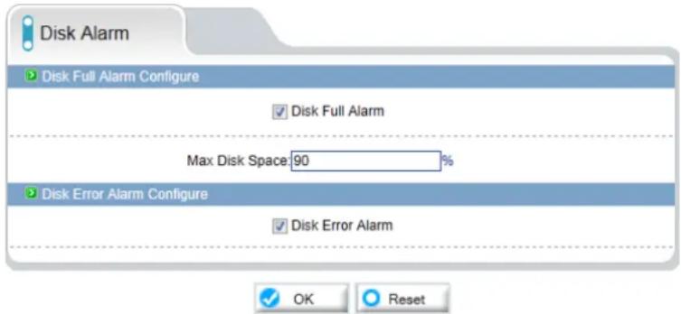
The Disk Alarm page allows you to configure alarms if there is an issue with the recording disk. You can configure a Disk Full Alarm or a Disk Error Alarm. A Disk Full Alarm triggers an alarm when the recording disk is full or exceeds a certain percentage. A Disk Error Alarm triggers an alarm if there is an error accessing or writing to the recording disk.
Alarms can be viewed using the Alarm Manager in Syncro-V (see the Syncro-V manual on the CD for details).
To configure Disk Alarms:
- Click Alarm Configuration→Disk Alarm.
-
Check Disk Full Alarm to enable Disk Full Alarms.
-
Under Max Disk Space, enter the disk full percentage that will trigger an alarm (e.g. a Disk Full Alarm will be triggered when the recording disk is 80% full).
- Check Disk Err or Alarm to enable Disk Error Alarms.
- Click OK.
8.8.2 Motion Alarm
The Motion alarm page allows you to configure camera motion detection alarm settings. You must enable motion detection to use local (e.g. microSD/SD card or FTP recording) motion detection recording. For instructions on setting up local recording, see "8.9 Local Record" on page 43. For details on motion recording using Syncro-V, see the Syncro-V manual on CD.

To configure motion detection:
- Click Alarm Configuration→Motion Alarm.
-
Check Enable under Motion Parameter.
-
Click Schedule to configure a motion detection schedule. The Schedule Time Setting menu opens.
NOTE: If the Schedule Time Setting menu does not open, disable any popup blockers.
- Configure the weekly schedule. The schedule is divided into 3 periods, and motion detection will be enabled in all times during all 3 periods.
-
Click Motion Area, and configure up to 8 motion detection areas:
-
Select Area Motion or Area Mask to configure motion detection areas.
- Area Motion allows you to select areas where motion detection is enabled.
- Area Mask enables the entire image for motion detection, and allows you to select areas to disable motion detection.
-
Right-click to delete the last created area.
-
Under Sensitivity, select the sensitivity for motion detection: Low, Medium, or High.

- Click OK to save your settings.
8.9 Local Record
Local Record contains the following sub-menus:
- Record Policy
- Record Directory
8.9.1 Record Directory

Record Directory allows you to configure the microSD/SD memory card, NAS, and FTP storage locations. It also allows you format the microSD/SD card.
IMPORTANT: You must format the microSD/SD card using the camera before you can record to it.
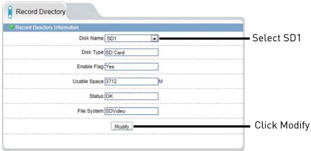
To format the microSD/SD card to enable recording:
NOTE: Formatting the microSD/SD card erases all data on the card.
- Click Local Record→Record Directory.
- Make sure to disable all recording types in Record Policy before formatting the microSD/SD card. See "8.9.2 Record Policy" on page 48.
-
Under Disk Name, select SD1.
-
Click Modify. The Record Disk Path menu opens.
- Check Enable.

- Under File System, select SDVideo (recommended) or Ext3.
- Click Format. A window will appear to show the status of the formatting. Wait for the formatting to complete and then click OK.
NOTE: If the Record Disk Path menu does not open or formatting does not occur, disable any popup blockers.
To configure FTP storage location:
- Click Local Record→Record Directory.
2. Under Disk Name, select ftp.
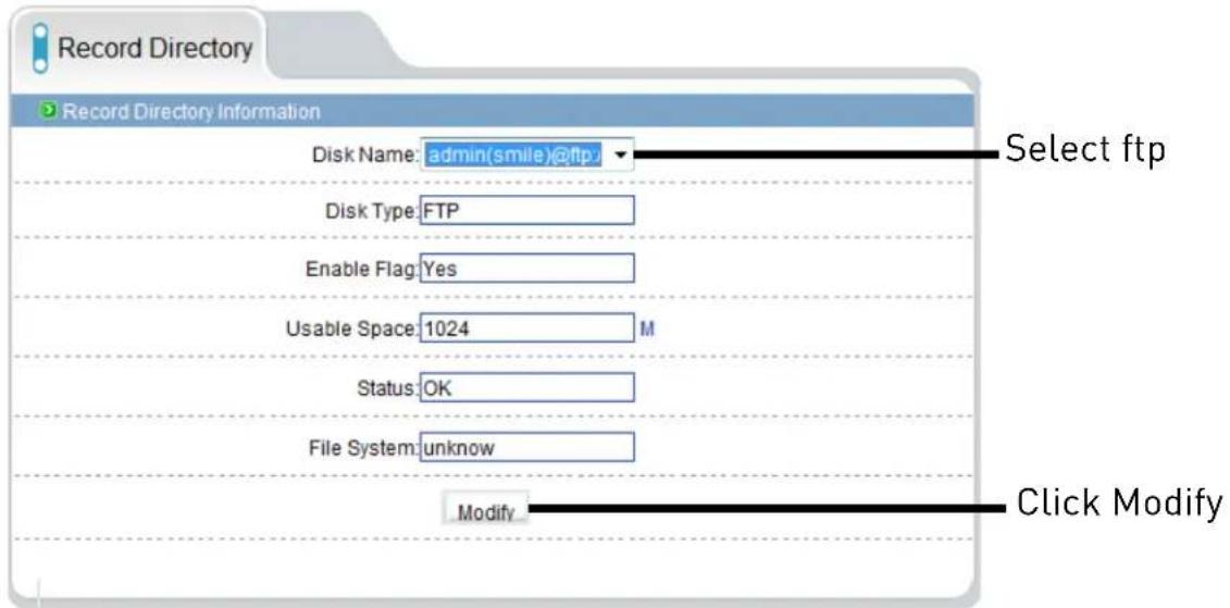
- Click Modify. The Record Disk Path opens.
- Check Enable.
- Configure the following:
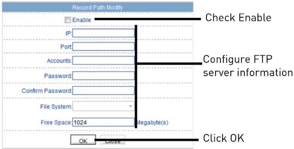
• IP: Enter the FTP server address.
- Port: Enter the FTP port number.
• Accounts: Enter the FTP account user name.
- Password/Confirm Password: Enter the FTP password.
- Free Space: Enter the amount of space (in MB) you would like to make available on the FTP server for recording.
- Click OK.
- Set up recording using the Record Policy sub-menu (see "8.9.1 Record Directory" on page 43). To access your recordings, use Syncro-V or manually access your FTP server.
NOTE: On the Record Directory page, Status will be OK when FTP is selected if FTP is accessible and all settings have been entered correctly.

To configure a NAS storage location:
- Click Local Record→Record Directory.
- Under Disk Name, select //.
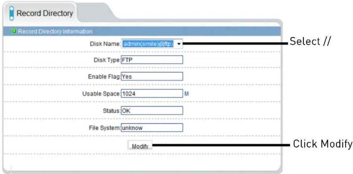
- Click Modify. The Record Disk Path menu opens.
4. Configure the following:

• IP: Enter the IP address of the NAS.
- Path: Enter the NAS folder where video files will be saved. NAS folder must be located directly under the root folder of the NAS (e.g. /public).
• Accounts: Enter the account user name for the NAS.
- Password/Confirm Password: Enter the account password for the NAS.
- File System: Enter the NAS file system (cifs or nfs).
- Use All Space: Check to enable the camera to record until the NAS is full. Uncheck to limit the amount of space the camera can record on and enter the amount of space (in MB) available to the camera under Free Space.
5. Click OK.
- Set up r recording using the Record Policy sub-menu (see "8.9.1 Record Directory" on page 43). To access your recordings, use Syncro-V or manually access your NAS device.
NOTE: On the Record Directory page, Status will be OK when NAS is selected if NAS is accessible and all settings have been entered correctly.

8.9.2 Record Policy

The Record Policy menu allows you to set the microSD/SD memory card, NAS, and FTP recording parameters. Once configured, the device can record video directly to a microSD/SD card, NAS, and FTP.
To enable recording to microSD/NAS/FTP:
-
Click Local Record→Record Policy.
-
Configure recording storage locations in the Record Directory sub-menu. See "8.9.1 Record Directory" on page 43.
NOTE: The camera will simultaneously record to all storage locations that have been enabled in Record Directory.
- To enable scheduled or continuous recording, check Enable under Schedule Record. Select 7*24 H Record to record video continuously at all times, or, select Schedule Record to create a schedule for recording.
- If you select Schedule Record, click Schedule and configure recording times. The schedule is divided into 3 periods, and the camera will record
during all selected times in all 3 periods. Click OK when finished configuring the recording schedule.
-
To enable Motion Alarm Recording, check Enable under Alarm Record. Configure Pre-recording and Post-recording times. Check Motion Alarm, Channel.
-
Under Stream, select the stream to use for recording. Stream1 is recommended if you want to record high quality video, stream2 is recommended if you want to save bandwidth or storage space.
-
Check Record Audio to enable audio recording.
-
Under St orage Rule, select Cycle Write to enable the camera to overwrite the oldest recorded data once the available space in the storage location is filled. Or, select Save Days to save video for a set number of days and enter the Number of Days desired. Note that you must have sufficient storage space to save the number of days entered.
-
Click OK to save changes.
NOTE: To view video from the SD/microSD card, FTP, or NAS, use Syncro-V's playback features, see the Syncro-V manual on the CD for details. You can access video saved to FTP or NAS by manually accessing your FTP server or NAS device.
8.10 Privacy Masking

The Privacy Masking menu allows you to create up to 5 privacy areas that will not appear in recordings. You can cover up to 8% of the total image area.
To configure privacy areas:
- Click Privacy Masking.
- Check Enable Privacy Masking.
- Click and drag inside the video area to configure privacy areas. Privacy areas will be shown as green rectangles. Right-click to delete the last created area.
- Click OK. An error message appears if the masks configured exceed 8% of the total image area.
8.11 Network Service
Network Service contains the following sub-menus:
- DDNS
- PPPoE (Not supported)
8.11.1 DDNS
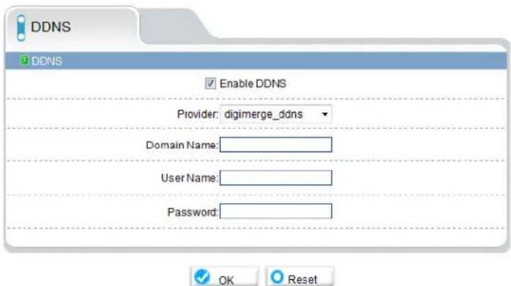
The DDNS sub-menu allows you to configure DDNS settings. Before configuring DDNS settings, you must register the camera for a free Digimerge DDNS account (see “7. Configuring Remote Connection” on page 18).
To configure DDNS settings:
- Click Network Service→DDNS.
- Check Enable DDNS.
-
Configure the following:
-
Provider: Select digimerge_ddns.
- Domain Name: Enter the Domain Name you received from the confirmation email you received after you created your DDNS account.
NOTE: Connect to your camera using a web browser by entering http://, the Domain Name, colon, and then the HTTP port. For example, if the Domain Name is tomsmith.digimerge.net, use the address http://tomsmith.digimerge.net:80.
- User Name: Enter the User Name you received in the confirmation email.
-
Password: Enter the Password you received in the confirmation email.
-
Click OK to save settings.
8.12 Service Center
Service Center contains the following sub-menus:
- SMTP
• Alarm Center (not supported)
8.12.1 SMTP (Email Alert Setup)

The SMTP sub-menu allows you to configure email alerts when motion alarms occur. Email alerts will include a .jpg snapshot attachment.
Before setting up email alerts you must configure the following:
- Motion alarms must be enabled before the camera will send email alerts. See "8.8.2 Motion Alarm" on page 41.
- A static IP address must be configured for the camera and DNS servers must be entered. See "8.7.1 Local Network" on page 33.
To enable email alerts:
- Click Service Center→SMTP.
- Check Enable SMTP.
- Configure the following:
- SMTP Server Address: Enter the address for your SMTP server.
- SMTP Server Port: Enter your server's SMTP port number.
- User Name: Enter the SMTP account user name.
- Password: Enter the SMTP account password.
- Sender E-mail Address: Enter the email address that will be used to send email alerts.
- Recipient E-mail Address 1\~5: Enter up to 5 email addresses that will receive email alerts.
- Attachment Image Quality: Select the quality of the image attachments: High, Mid, or Low.
-
Transport Mode: Select the encryption type used by the server (SSL or STARTTLS) or select No encrypted if your server does not use encryption.
-
Click OK to save your settings. Click Send testmail to send a test email alert.
8.13 Privilege Manager
Privilege Manager allows you to configure user accounts and user groups.
Privilege Manager contains the following sub-menus:
- Group
- User
8.13.1 Group

The Group page (Privilege→Group) allows you to manage permissions for user groups. Users obtain permission from their group. The Administrators group contains all permissions and cannot be deleted or edited.
To add a user group:
- Click Add. The Add Group menu appears.
NOTE: If the Add Group menu does not appear, disable any popup blockers.
- Enter a name for the user group and click OK.

-
Under Group, select the new group.
-
Check the permis sions you would like to apply to this user group. You can check or un-check Select All to select all or no permissions.
-
Click OK to save your new user group.
To modify a user group:
-
Under Group, select the group you would like to modify.
-
Click Modify to change the group name if needed, enter a new group name and click OK.
-
Change permis sions as needed and click OK.
To delete a user group:
- Click Delete. The Delete Group menu appears.
NOTE: If the Delete Group menu does not appear, disable any popup blockers.
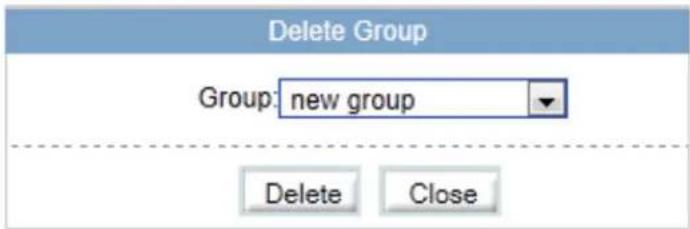
- Select the group you would like to delete and click Delete.
8.13.2 User

The User page (Privilege→User) allows you to manage user accounts. User accounts receive privileges based on their group. The admin account is the system administrator, and has full access to all functions.
To add a user account:
- Click Add. The Add User window appears.
NOTE: If the Add User menu does not appear, disable any popup blockers.

- Enter a User Name and Password for the account and repeat the password under Confirm.
- Under Group, select the desired user group for this account.
- Check Multi Login to allow the user account to log into the IP camera from multiple location simultaneously or un-check to limit the account to a single location at a time.
- Click OK to save the new user account.
To modify a user account:
- Select the user account under User and click Modify.
- Modify the ac count details as needed and click OK.
To delete a user account:
- Under User, select the user account and click Delete. Click OK to confirm.
8.13.3 Unlocking User Accounts
The admin account is the only account that can unlock user accounts that have been locked out. User accounts are locked out if the wrong password is entered 3 or more times.
To unlock a user account:
- Login to the camera as admin.
- Click Privilege Manager→User.

- Under User, select the locked user account.
- Click Unlock to unlock the account.
8.14 Protocol
Protocol contains the following sub-menus:
- Protocol
• Security (Not supported)
NOTE: Do not check User Verification in the Security sub-menu, as it may block ONVIF software from detecting the camera.
8.14.1 Protocol
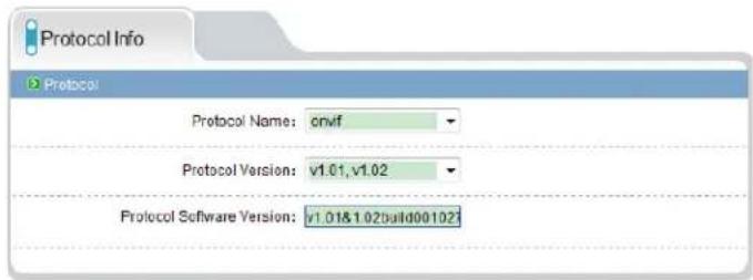
The Protocol page (Protocol→Protocol) allows you to view ONVIF protocol settings.
8.15 Device Restart

Click Device Restart. Click Restart then click OK to restart the camera.
8.16 Default Settings
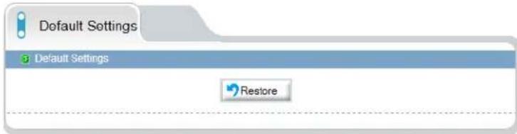
Click Default Settings. Click Restore then click OK to restore the camera to factory default settings. The camera will reboot.
8.17 Sensor Configuration
The Sensor Configuration menu is used to adjust camera image settings.
To configure camera image settings using the Sensor Configuration menu:
- Log into the camera using a web browser, and from the Live Video page, right-click on the video area and select Sensor Config.

- Click Save to save setting changes.
- Click Reset to revert to the last saved changes.
- Click Factory Setting to revert all camera sensor settings to factory defaults.
- Click Cancel to exit.
TIP: Hold the mouse over the tabs to see the full name of the tab.
8.17.1 Image Adjust

Adjust the Brightness, Saturation, and Contrast settings for the image.
8.17.2 Shutter Control

Adjust the camera shutter settings.
- ShutterMode: Select AutoShutter or FixedShutter.
- MaxShutter: Sets the upper limit of the shutter speed when AutoShutter is selected.
- FixedShutter: Sets the shutter speed when FixedShutter is selected.
8.17.3 Gain Mode
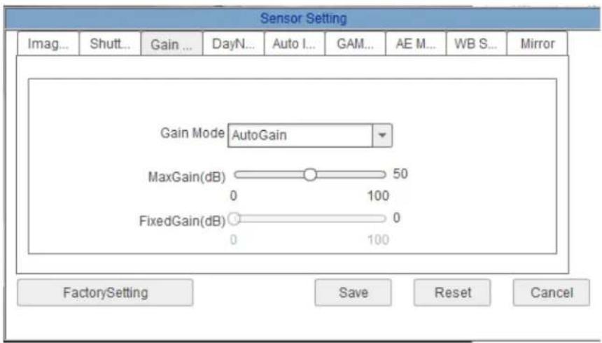
Select gain mode and adjust gain settings.
- Gain Mode: Select AutoGain or FixedGain.
- MaxGain (dB): Select the maximum gain value when AutoGain is selected.
- FixedGain (dB): Select the gain value when FixedGain is selected.
8.17.4 Day/Night Mode

Configure color settings for night mode.
- Night Color: Select Black_White to have the camera switch to black and white during night mode or select Multicolor to have the camera remain in color during night mode.
8.17.5 Auto Iris
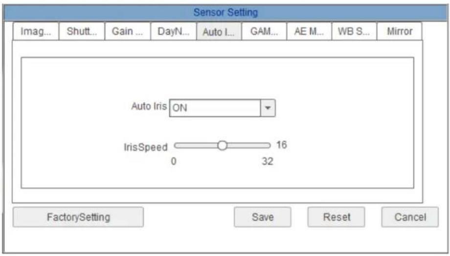
Set Auto Iris settings.
- Auto Iris: Select ON to enable or OFF to disable.
- Iris Speed: If Auto Iris is set to ON, select Auto Iris speed.
8.17.6 Gamma

Adjust Gamma.
- Gamma: Select gamma setting: Standard, High, Middle, Low, or Dynamic.
Set the Auto-Exposure Meter Mode from one of the following:
- Multi-Pattern: When metering light, entire image is metered symmetrically.
- Center-Weighted: When metering light, priority is given to the center of the image.
- Vertical Center-Weighted: When metering light, priority is given to the vertical center of the image.
- Horizontal Center-Weighted: When metering light, priority is given to the horizontal center of the image.
8.17.8 WDR

Configure settings for Digital Wide Dynamic Range.
- Control Mode: Select ON to enable Digital Wide Dynamic Range or OFF to disable.
NOTE: Enabling Digital Wide Dynamic Range may cause color distortion based on the lighting. If you notice color distortion, it is recommended to turn Control Mode to OFF.
- Working Mode: Select DLO (Digital Side Overflow) for environments with few moving objects. Select MC (Motion Compensation) for environments with multiple moving objects.
8.17.9 WB Setting

Adjust White Balance.
- WB Mode: Select Auto for automatic white balance or Manual to manually set the white balance.
- Manual Mode: Select a mode for the lighting conditions or select Customized and manually adjust the RedGain and BlueGain.
8.17.10 Mirror
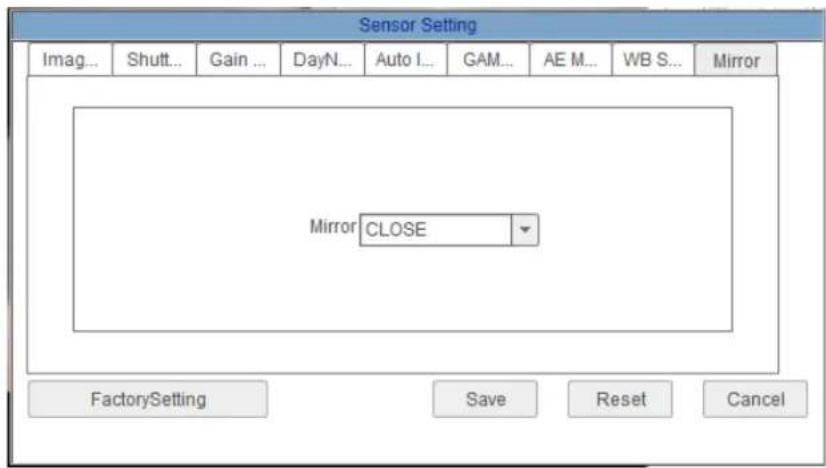
Enable/disable image mirroring.
- Mirror: Select Horizontal to mirror the image horizontally, Vertical to mirror vertically, or Picture Flip to mirror both horizontally and vertically. Select Close to disable image mirroring.
8.17.11 Noise Filter
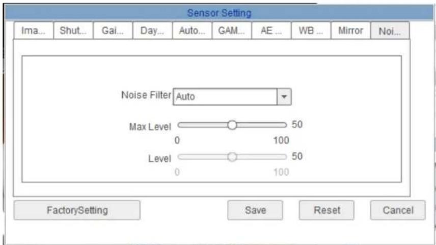
Configure noise filter settings.
- Noise Filter: Select Auto for automatic noise filtering or Manual.
- Max Level: Select the maximum level for automatic noise filtering.
- Level: Select the level for manual noise filtering.
9. RESETTING TO FACTORY DEFAULTS
Follow the steps below to revert all settings to factory defaults. The camera must be connected to power to perform a factory reset.

-
Loosen the three tamper screws using the provided allen key. Lift the dome cover.
-
Remove camera cover by squeezing the back and front of the cover (as indicated by the arrow indicators) at the same time and lifting it up and away from the lens.

Reset

natural_image
Technical line drawing of a mechanical assembly with no visible text or symbols-
Press and hold the black reset button for 5 seconds then release the button to reset the camera to factory defaults.
-
Re-attach the camera cover, using the thumb screw as a guide, until it snaps into place.

Arrow on camera base Arrow on camera module (inside camera)
Arrow on dome cover
Correct Arrow Alignment
- Re-attach the dome cover.
Align the arrows as shown in the diagram to ensure a
waterproof seal.
Use the allen key to tighten the tamper screws.
NOTE: Make sure dome cover cord does not get caught in the rubber seal.
10. DIMENSIONS
Camera Dimensions

Base Hole Screw Dimensions

11. TECHNICAL SPECIFICATIONS
Camera
| Sensor/DSP: | 1/2.5" CMOSProgressive Scan |
| Day/Night: | True Day/Night with ICR Filter.High Powered IR LEDs |
| Resolutions and Max supported frame rate: | 1920x1080 Full HD 2.1MP at 30fps |
| Min. Illumination: | Color: 0.1 lux@F1.2 @F1.2, AGCon/(0 Lux IR LEDOn) |
| Lens: | 2.8-12mm Vari-Focal |
| Horizontal Field of View: | 79.3° ~ 29.8° |
| IR LED: | 12pc Super Flux LEDs 850nm |
| IR Distance: | 65 feet/20 Meters |
| Video Output: | RJ45, Setup/Service BNC Video Out |
| Electronic Shutter: | Auto/User 1/5 - 1/50,0000 |
| Audio Compression: | G711 A-Law, G711 U-Law, RAWPCM |
Video
| Compression: | H-264 High Profile (Support Baseline Profile/ MJPEG) |
| Bit Rate (CBR/VBR): | Stream1 50Kbps - 12Mbps ; Stream2 10Kbps - 6Mbps ; Stream3 (MJPEG Fixed) |
| Quality Setting: | 1 - 9 (9 Highest) |
| Multi- Streaming: | User setting of Stream 1/2 at supported Resolutions, Stream3 fixed MJPEGStream |
| Brightness/Sharpness: | Variable 0~100/0~100 |
| Gain Control: | Auto/Fixed 8~102db |
| Orientation: | Horizontal Mirror/Vertical Flip |
| Text Overlay: | Time/Date/Camera/Custom OSD |
| Masking: | 3 User defined masking areas <8% of total picture |
Network
| Ethernet: | 1 Ethernet (10/100 Base-T) RJ-45 Connector one network coupler supplied |
| TCP/IP: | IPv4/IPv6 (DHCP/Fixed) |
| Compliance: | Onvif 2.1 (1.02 backward compatible) |
| RTSP Video: | Standard RFC2326, Support QuickTime/VLC Player. User security authentication (Enabled/Disabled) |
| Web Language: | English, Chinese, Russian, Polish |
| Recording Simultaneous: | Local microSD Memory*, Remote FTP server, TCP/UDP CMS, RTSP connection(stream 1,2 or 3) |
| Network Protocols: | HTTP, TCP/IP, UDP/IP, RTSP, FTP, DHCP, NTP, PPoE.Video streaming from SDK & NVMS/NVR software or 3rd party applications.User Ports setting for Web port, RTSP Port, and SDK ControlPort and Alarm Port. |
* microSD card not included. Up to 64GB.
Audio
| Input/Output: | 1 x RCA Input/1 x RCA Audio Output 1v Line Level |
| Audio Compression: | G711 A-Law, G711 U-Law, RAWPCM |
General
| Power: | 12V DC, 550mA/6.6W |
| Power over Ethernet: | PoE Class 3, 13W max |
| Operating Temperature: | -4°F to 122°F/-20°C to 50°C |
| Operating Humidity | 10% - 85% RH |
| Approvals | CE/FCC/RoHS Compliant/IP66/IK10 |
| Product Dimensions | 5.1 x 4.4"/130 x 112 mm |
| Product Weight | 0.85kg/1.87lb |
Dimensions

Product Information
| UPC: | 8-41430-00736-4 |
| Weight: | 1.21kg/2.7lbs |
| Package Dimensions:(W x D x H) | 170mm x 160mm x 180mm6.7" x 6.3" x 7.1" |
| Package Cube: | 0.0049 cbm/0.173cu ft |
What's Included:
| Software CD: |
| Milestone XProtect ^ GO Software |
| CMS-DH Pro |
| Syncro-V |
| Auto Port Forwarding wizard |
| User Manual |
| Surface Mounting Template |
Accessories:
| MNTV2XB | Junction Box |
| MNTV2XC | Ceiling Mount |
| MNTV2XW | Wall Mount |
| MNTV2XP | Pole Mount |
| MNTV2XPC | Pendant Cap |
| MNTV2XR | Corner Mount |

Because our products are subject to continuous improvement, Digimerge reserves the right to modify product design and specifications without notice and without incurring any obligation. E&O.E.
12. TROUBLESHOOTING
Can't find the camera IP address using Syncro-V or other software:
- Make sure Ethernet and/or DC power cables are correctly connected to the camera.
- Make sure the PoE switch or DC power source meets the camera's power requirements (class 3 PoE / 550mA / 6.6W / 12V). If using PoE, make sure the PoE switch is powered on.
- Make sure the PC is on the same network as the camera. Ping the camera's IP address. On your PC, go to Start → Programs → Accessories → Command Prompt. Type ping then the camera's local IP address and press Enter. If you get the message "Request timed out," PC and camera are not on the same network or camera is not connected. Camera is connected if you receive replies.
- Connect the BNC test cable to the camera and the other end to a test monitor. The monitor display shows the camera's IP address. A default IP address of 192.168.0.120 may mean that the camera cannot obtain an IP address from the router. Check the Ethernet/power connections and router configuration.
- Camera set for static IP mode using an incorrect IP address. By default, the camera is set for DHCP mode, which means it will automatically obtain an IP address from your router. Reset the camera to factory default settings by removing the camera cover and pressing the reset button for 5 seconds or more.
Can't connect to the camera on a web browser using local IP address:
- See steps above.
- Verify the camera's local IP address using one of the methods listed in "6. Finding the Camera's IP Address" on page 14.
Can't connect to camera on a web browser using a DDNS address:
- Digimerge DDNS address entered incorrectly into the address bar. Make sure to enter http://, the Domain Name you received in the confirmation email, followed by colon, and the HTTP port number of the camera (e.g. http://tomsmith.digimerge.net:80).
- DDNS account not created. Go to http://www.ddns.digimerge.net and create a DDNS account, and then input the DDNS account information into the camera DDNS page (Network Service→DDNS).
- DDNS information not configured on camera. See “8.11.1 DDNS” on page 51.
- Port forwarding not set up. Make sure the HTTP port (default: 80) and Control port (default: 30001) are forwarded on your router to the camera's local IP address.
- Multiple cameras using same port number to connect. Configure each camera to use different ports and port forward the new ports (see “8.7.2 Device Port” on page 34 for details on changing camera ports).
Can't connect to camera video on a web browser:
- If using IE, make sure to install ActiveX plug-in or Adobe Flash Player. For more information, see "8.3 Internet Explorer® Setup" on page 25.
- If using a browser other than IE (e.g. Google Chrome, Apple Safari, Mozilla Firefox), make sure latest version of Adobe Flash Player is installed.
Video performs poorly on browser:
- Insufficient bandwidth available for high-quality stream1. Select stream2 under Stream. Stream2 provides a lower-resolution to conserve bandwidth and improve performance on low-bandwidth connections.
- If using IE, click the message above the video area to use ActiveX plug-in instead of Flash Player. ActiveX may provide smoother video performance.
User account is locked:
- User accounts are locked when the password has been incorrectly entered 3 times. To unlock the account, login to the camera web interface as admin. Click Privilege Manager→User. Under User, select the locked user account and click Unlock to unlock the account.
Need Help?
Please make sure to visit our website www.digimerge.com to receive product updates and information.
3 Easy Ways To Contact Us

natural_image
Man using a laptop on a white sofa, no visible text or symbols
natural_image
Man using a laptop in an office setting (no visible text or symbols)
natural_image
Woman sitting at a desk with a phone and computer, smiling at the camera (no visible text or symbols)Online:
Product support is available 24/7 including product info rm ation, user manuals, quick start up gui de s and FAQ's at w ww. digi merge.com
By Email:
Te ch ni cal support (for tec hn ical/installat io n is su es) tech@digimerge.com
By Phone:
No rt h Am er ica: 1-866-816-5919 Te ch ni cal support (for tec hn ical/installat io n is su es) Mo n- Fri 8.00 a m to 8.00pm EST

natural_image
Close-up of a smiling man wearing a headset, with another person partially visible in the background (no text or symbols)We welcome your feedback at info@digimerge.com
For more information, visit www.digimerge.com


DIG!MERGE | Right for Business
DNV14TL2
English Version 1.0
- DIG!MERGE | Right for Business
- DNV14TL2
- IR Vandal Dome IP Camera
- Instruction Manual
- CAUTION
- RISK OF ELECTRIC SHOCK DO NOT OPEN
- Important Safeguards
- Installation
- Service
- G
- Use
- General Precautions
- FCC CLASS A NOTICE
- NOTE
- Features
- TABLE OF CONTENTS
- Getting Started .... 1
- Connection 6
- Camera Installation.... 7
- Junction Box Plate 12
- Junction Box Installation Types 13
- Finding the Camera's IP Address 14
- Configuring Remote Connection 18
- Web Configuration 24
- GETTING STARTED
- Default Camera Username, Password, and Ports
- Mounting Screw Kit:
- Camera Interior Overview
- Mounting Accessories
- ONVIF Compatibility and Included Software Overview
- Milestone XProtect Go®
- Syncro-V
- CMS-DH PRO
- CONNECTION
- CAMERA INSTALLATION
- All Installation Methods
- Method 1 - Direct Attach Install
- Method 2 - Camera Base Install
- Method 3 - Junction Box Install
- Reattaching the Camera Module
- Go to step 4 to complete installation.
- JUNCTION BOX PLATE
- Junction Box Plate Dimensions and Fitting
- JUNCTION BOX INSTALLATION TYPES
- Two Gang Fitting (Recommended)
- 4S Fitting
- Octagon Fitting
- FINDING THE CAMERA'S IP ADDRESS
- Finding the Camera's IP Address Using Syncro-V
- Finding the Camera's IP Address using UPnP in Windows® 7
- Finding the Camera's IP Address using Bonjour® in Mac OS®
- Finding the Camera IP using the BNC Test Cable
- CONFIGURING REMOTE CONNECTION
- Step 1 of 6: Locate the camera's local IP address:
- Step 2 of 6: Port Forward your router:
- Step 3 of 6: Locate your camera's MAC address:
- Step 4 of 6: Register for Digimerge DDNS:
- To setup your free Digimerge DDNS account:
- Step 5 of 6: Enable DDNS on the camera:
- Step 6 of 6: Connect to the camera's DDNS address:
- Connecting to a DDNS address using Syncro-V
- Supported Browsers
- Chrome, Firefox, and Safari Setup
- Internet Explorer® Setup
- Step 1 of 2: Change Internet Explorer security settings for ActiveX®:
- Step 2 of 2: Log into camera:
- Web Interface/Live Video Overview
- Live Video Menu
- The Live Video Menu contains the following options:
- Configuring Camera Settings
- Device Info
- To configure the Device Name:
- Stream Configuration
- To configure video streaming settings:
- Device Configuration
- Local Network
- To configure the camera's networking parameters:
- Device Port
- To change camera ports:
- Camera
- To change the Channel Name:
- To change the video system frequency:
- Date & Time
- You can set the camera's date and time the following ways:
- To set the camera's date and time using an NTP server:
- To sync the camera's date and time to your computer's system time:
- To set the camera's date and time manually:
- OSD
- To configure the camera OSD:
- Microphone
- To configure microphone settings:
- BNC Video Output
- Language
- To change the language for the OSD and email alarms:
- Alarm Configuration
- Disk Alarm
- To configure Disk Alarms:
- Motion Alarm
- To configure motion detection:
- Local Record
- Record Directory
- To format the microSD/SD card to enable recording:
- To configure FTP storage location:
- Under Disk Name, select ftp.
- To configure a NAS storage location:
- Configure the following:
- Click OK.
- Record Policy
- To enable recording to microSD/NAS/FTP:
- Privacy Masking
- To configure privacy areas:
- Network Service
- DDNS
- To configure DDNS settings:
- Service Center
- SMTP (Email Alert Setup)
- Before setting up email alerts you must configure the following:
- To enable email alerts:
- Privilege Manager
- Group
- To add a user group:
- To modify a user group:
- To delete a user group:
- User
- To add a user account:
- To modify a user account:
- To delete a user account:
- Unlocking User Accounts
- To unlock a user account:
- Protocol
- Protocol
- Device Restart
- Default Settings
- Sensor Configuration
- To configure camera image settings using the Sensor Configuration menu:
- Image Adjust
- Shutter Control
- Gain Mode
- Day/Night Mode
- Auto Iris
- Gamma
- WDR
- WB Setting
- Mirror
- Noise Filter
- RESETTING TO FACTORY DEFAULTS
- DIMENSIONS
- TECHNICAL SPECIFICATIONS
- TROUBLESHOOTING
- Can't find the camera IP address using Syncro-V or other software:
- Can't connect to the camera on a web browser using local IP address:
- Can't connect to camera on a web browser using a DDNS address:
- Can't connect to camera video on a web browser:
- Video performs poorly on browser:
- User account is locked:
- Need Help?
- Easy Ways To Contact Us
- Online:
- By Email:
- By Phone:
- English Version 1.0
Brand : Digimerge
Model : SyncroIP DNB14TL2
Category : Security Camera