ALA15T - Speaker Atlas Sound - Free user manual and instructions
Find the device manual for free ALA15T Atlas Sound in PDF.


| Product Type | Professional Loudspeaker |
| Model | ALA15T |
| Brand | Atlas Sound |
| Transformer Power (70.7V) | 60W with selectable taps: 7.5, 15, 30, 60W |
| Low Impedance Operation | 8Ω or 6Ω (with jumper removed) |
| Input Connectors | Barrier terminal strip and NL4 Speakon connector |
| Mounting | Wall-mounted with adjustable wall brackets (short, medium, long) |
| Horizontal Adjustment | Yes, via sliding mount blocks and bolts |
| Angle Adjustment | Yes, using speaker bracket length and wall bracket spacing (see manual tables) |
| Safety Precautions | Risk of hearing damage; secure mounting required; qualified installer needed for overhead installation |
| Compliance | Must adhere to local building codes and safety standards |
| Included Accessories | Wall brackets, sliding mount blocks, bolts and washers |
| Tools Required | Level, appropriate wall anchors, screwdriver, wrench |
| Wiring | Run from amplifier to speaker; ensure amplifier is off during connection |
Frequently Asked Questions - ALA15T Atlas Sound
User questions about ALA15T Atlas Sound
0 question about this device. Answer the ones you know or ask your own.
Ask a new question about this device
Download the instructions for your Speaker in PDF format for free! Find your manual ALA15T - Atlas Sound and take your electronic device back in hand. On this page are published all the documents necessary for the use of your device. ALA15T by Atlas Sound.
USER MANUAL ALA15T Atlas Sound
Installation Instructions
Safety Instructions
Please read carefully before installing or operating.
- Read all instructions carefully
- Heed all warnings
• Assure that the speaker is securely mounted
• Always assure amplifier power is off before making any connections - Keep instructions for future reference
- Should any questions arise after reading this document, please call Atlas Sound Tech Support at 800-876-3333
Hearing Damage
CAUTION: All professional loudspeaker systems are capable of generating very high sound pressure levels. Use care with placement and operation to avoid exposure to excessive levels that can cause permanent hearing damage.
Suspension and Mounting
Installing speaker systems requires training and expertise. Improper speaker installation may result in injury, death, equipment damage, and legal liability. Installation must be carried out by fully qualified installers, in accordance with all required safety codes and standards at the place of installation.
Legal requirements for overhead installation vary by municipality, please consult the Building Inspector office before installing any product and thoroughly check any laws and bylaws prior to installation. Installers that lack the skills, training, and proper ancillary equipment to install a speaker system should not attempt to do so.
Installation
- Run the wiring from the power amplifier to the location desired for mounting the ALA Series speaker.
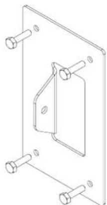
- Attach the wall bracket to the wall. Use a level to be certain that the wall bracket is straight. Secure the wall bracket to the wall. Be sure to use the appropriate wall anchors when attaching the bracket. Use all four screw holes for maximum integrity and safety.
Note: Hardware for attaching the wall bracket to the wall is not included.
natural_image
Technical line drawing of a mechanical bracket assembly with bolt holes (no text or symbols)Fig. 1
- Attach the upper wall bracket as required.
A. The location of the upper wall bracket will vary according to the angle that the speaker will be used.
B. If the speaker will be parallel to the wall, the upper wall bracket can be located 25" to 38" center to center. Two short speaker brackets, one on the top and one on the bottom will be used. Refer to figure 2a.
C. For an angled installation, please refer to the tables and figures below to determine the center to center distance for the wall brackets.
D. For higher angles of tilt, use the long speaker bracket. Refer to figure and table 2b.
E. For lower angles of tilt, use the medium speaker bracket. Refer to figure and table 2c.
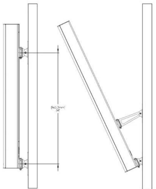
Fig. 2a
| ALA15T / ALA20T | |
| ANGLE C-C IN | |
| 26.06° 19' | |
| 24.67° 20' | |
| 23.42° 21' | |
| 22.30° 22' | |
| 21.28° 23' | |
| 20.35° 24' | |
| 19.50° 25' | |
| 18.72° 26' | |
| 18.01° 27' | |
| 17.34° 28' | |
| 16.73° 29' | |
| 16.15° 30' | |
| 15.62° 31' | |
| 15.12° 32' | |
| 14.65° 33' | |
| 14.21° 34' | |
| 13.80° 35' | |
| 13.41° 36' | |
| 13.04° 37' | |
| 12.69° 38' | |
| 12.36° 39' | |
| 12.04° 40' | |
| 11.75° 41' | |
| 11.46° 42' | |
| 11.19° 43' | |
| 10.93° | 44' |
| 10.69° | 45' |
| 10.45° | 46' |
| 10.23° | 47' |
| 10.01° | 48' |
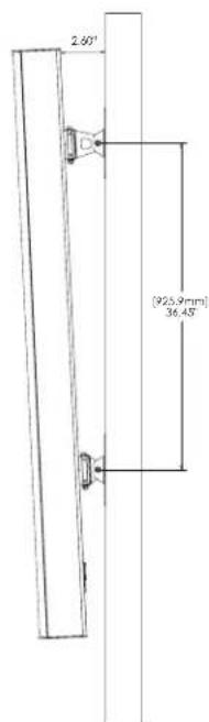
Fig. 2c
Table. 2b
- Attach the short speaker bracket to the lower sliding mount block.
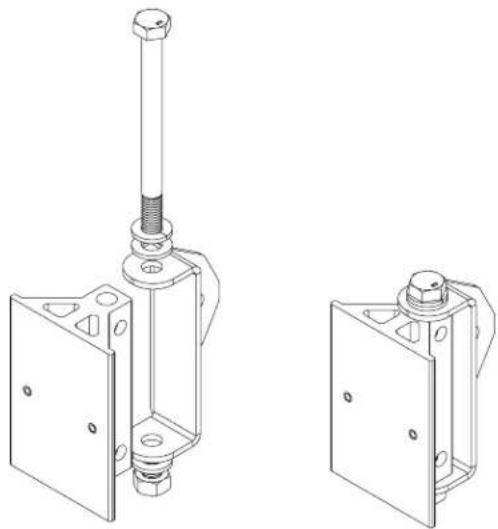
A. Position the short speaker bracket over the lower sliding mount block as shown in Fig. 3.
B. Insert the 100mm M8 bolt through the short speaker bracket and the lower sliding mount block. Be sure to include the plain washers and one lock washer as shown.
Note: For angled installation, skip step 4C and proceed to step 4D.
natural_image
Technical line drawing of two mechanical components with no visible text or symbolsFig. 3 (Sliding Mount Block shown not attached to speaker for clarity)
C. If the speaker will be parallel to the wall, repeat steps 4A and 4B for the upper sliding mount block.
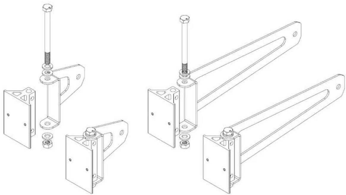
D. Position the medium or long speaker bracket over the upper sliding mount block as shown in Fig. 4a or Fig. 4b.
E. Insert the 100mm M8 bolt through the speaker bracket and the sliding mount block. Be sure to include the plain washers and one lock washer as shown.
natural_image
Technical line drawings of mechanical brackets and mounting fixtures (no text or symbols)Fig. 4a and 4b (Sliding Mount Block shown not attached to speaker for clarity)
- Attach the speaker bracket to the wall bracket.
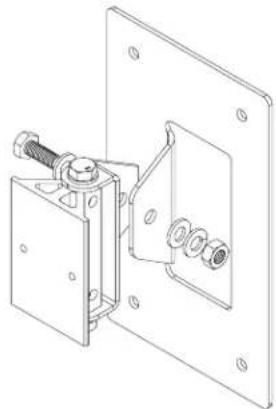
A. Insert the 20mm M8 bolt through the short speaker bracket and the lower wall bracket as shown in Fig. 5. Be sure to include the plain washers and one lock washer as shown.
natural_image
Technical line drawing of a mechanical assembly with mounting bracket and housing (no text or symbols)Fig. 5 (Sliding Mount Block shown not attached to speaker for clarity)
B. Insert the 20mm M8 bolt through the medium or long speaker bracket and the upper wall bracket as shown in Fig. 6a and 6b. Be sure to include the plain washers and one lock washer as shown.
C. Adjust horizontal position of the speaker and torque all bolts sufficiently to hold position.

natural_image
Technical line drawing of three mechanical assembly components with mounting brackets and mounting holes (no text or symbols)Fig. 6a and 6b (Sliding Mount Block shown not attached to speaker for clarity)
- Establish electrical connection. All models include a built-in, high efficiency 60 Watt 70.7V transformer with 7.5, 15, 30, and 60 Watt taps as shown in Fig. 7.
Note: A removable jumper and additional pole on the terminal block is included for transformer operation. The jumper must be removed for low impedance (8Ω or 6Ω) direct coupled operation.
Connections are provided on the terminal for both transformer and low impedance connection. An NL4 Speakon ^ connector is included for low impedance (8Ω or 6Ω) direct coupled operation.
Note: When using the Speakon ^® input connection, the jumper must be removed from the barrier terminal.
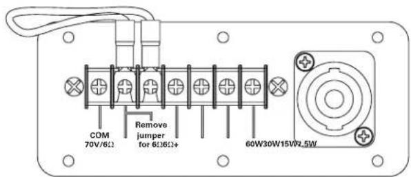
Fig. 7
ALA15T Dimensions
![DETAIL A SCALE 1 : 2 [49.37] 1254.0 [4.49] 114.0 [4.61] 117.0 [5.25] 133.3 [5.43] 137.9 [3.15] 80.0 [0.25] Ø6.4 [0.83] 21.0 [5.43] 137.9 [0.33] Ø8.3 [0.59] 15.0 [0.89] 22.5](/content/2026/06/1202852/images/6ca46d709ff3d1224cb5feef05405eea3e3182ccf2527ea8bcbd439a7105fcaa.jpg)
ALA20T Dimensions
![DETAIL A SCALE 1 : 2 [65.75] 1670.0 [3.15] 80.0 [.25] Ø6.4 [.83] 21.0 [5.43] 137.9 [.33] Ø8.3 [.59] 15.0 [.89] 22.5 [4.61] 117.0 [4.49] 114.0](/content/2026/06/1202852/images/2a77390f9b9c080b30f724ac04167de2fc214b0d812ce34890d0e1f8a4d01ae5.jpg)
©2015 Atlas Sound L.P. and Innovative Electronic Designs, LLC. All Rights Reserved. Atlas Sound is a trademark of Atlas Sound L.P. IED is a registered trademark of Innovative Electronic Designs, LLC. All other trademarks are the property of their respective owners. All specs are subject to change without notice. ATS005302 RevB 11/15
Brand : Atlas Sound
Model : ALA15T
Category : Speaker