
PDU15BV14F - Surge protector power strip CyberPower - Free user manual and instructions
Find the device manual for free PDU15BV14F CyberPower in PDF.

| Product Type | Power Distribution Unit (PDU) - Basic Series 0U Vertical |
| Model Number | PDU15BV14F |
| Rack Form Factor | 0U vertical (mounts on rack rails) |
| Dimensions (H x W x D) | 24 x 1.75 x 1.5 in (60.96 x 4.45 x 3.81 cm) |
| Input Voltage | 100-120 V AC |
| Maximum Input Current | 12 A (derated per UL) |
| Input Plug Type | NEMA 5-15P |
| Power Cord Length | 10 ft (3.05 m) |
| Output Voltage | 100-120 V AC |
| Maximum Output Current | 12 A (derated per UL) |
| Outlet Type & Quantity | 14 x NEMA 5-15R |
| Circuit Breaker | 15 A thermal, resettable |
| Mounting Options | Vertical with brackets or keyhole mounts (hardware included) |
| Operating Temperature | 32°F to 122°F (0°C to 50°C) |
| Humidity | 0% to 95% non-condensing |
| Maximum Altitude | 13,100 ft (4,000 m) |
| Safety & Compliance | UL 62368, UL 60950-1, RoHS |
| Grounding | External site-ground screw provided |
| Package Contents | PDU unit, mounting brackets, keyhole pegs, screws, cord retention tray, cable ties, documentation |
| Warranty | 3 years (USA/Canada) |
Frequently Asked Questions - PDU15BV14F CyberPower
User questions about PDU15BV14F CyberPower
0 question about this device. Answer the ones you know or ask your own.
Ask a new question about this device
Download the instructions for your Surge protector power strip in PDF format for free! Find your manual PDU15BV14F - CyberPower and take your electronic device back in hand. On this page are published all the documents necessary for the use of your device. PDU15BV14F by CyberPower.
USER MANUAL PDU15BV14F CyberPower
Power Distribution Unit
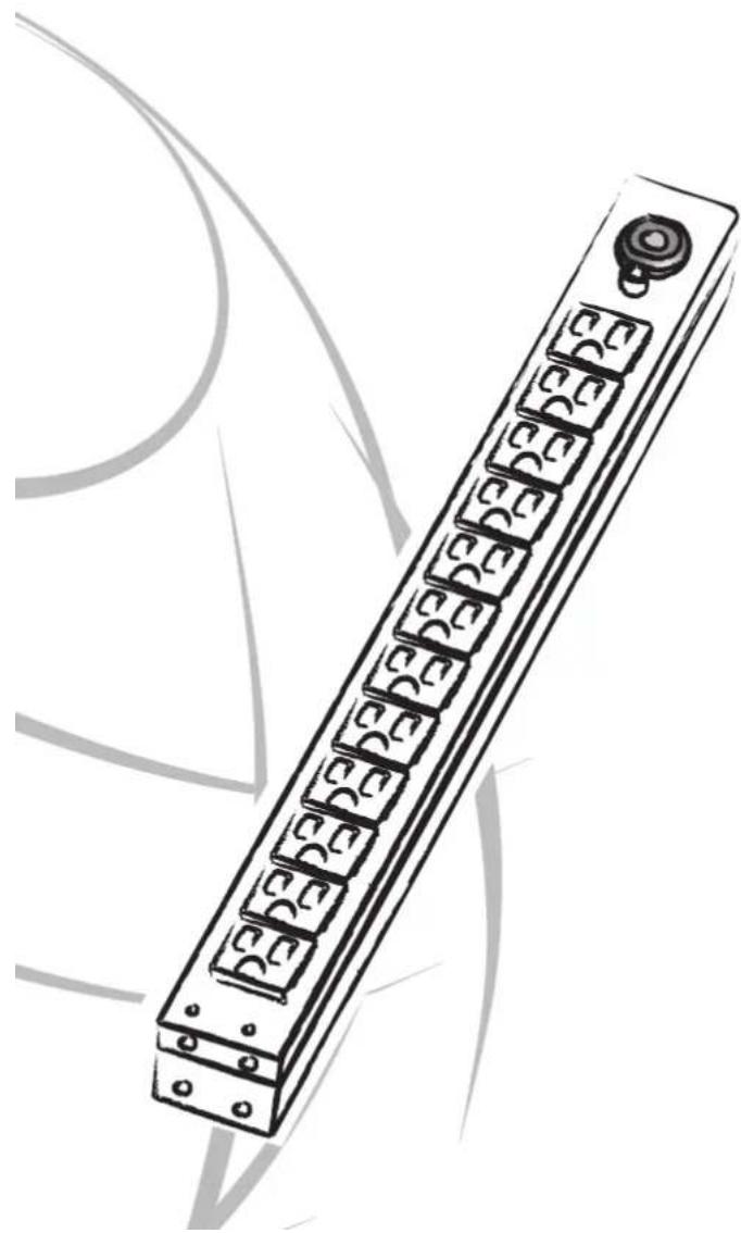
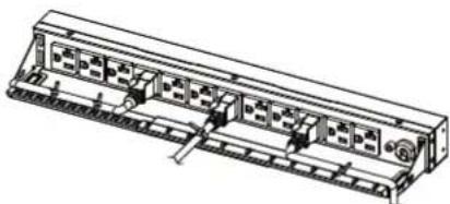
natural_image
Illustration of a long rectangular electronic component with multiple ports and a button, no text or symbols present.Table of Contents
Model List ....1
PDU Naming Convention .... 1
Package Contents 2
Safety Precautions 3
Horizontal Installation. (1U models only)....4
Vertical Installation with Brackets ....5
Vertical Installation - Keyhole Mounts (0U models only) .....6
Cord Retention Tray installation 6
Meter Configuration ....6
Locking Power Cord - For IEC Type PDU ....7
Input Power Cord 7
Output Power Cord 7
Electrical Installation 8
Troubleshooting 8
Product Features
Technical Specification 9
Basic Series (1U) 9
Basic Series (0U) 13
Metered Series (1U) 15
Metered Series (0U) 16
Conformance Approvals ....19
Customer Service & Warranty ......20
Model List:
Basic Series (1U):
| PDU15B8R | PDU15B6F8R | PDU20BHVCEE8R |
| PDU15B10R | PDU15B6F12R | PDU20BHVCEE12R |
| PDU15B12R | PDU20B10R | PDU30BT8F8R |
| PDU15B2F8R | PDU20BHVT8R | PDU30BT10F10R |
| PDU15B2F10R | PDU20BHVT12R | PDU30BHVT2F6R |
| PDU15B2F12R | PDU20BHVIC8R | PDU30BHVT4F8R |
| PDU15B4F12R | PDU20BHVIC12R |
Basic Series (0U):
| PDU15BV14F | PDU20BV32F | PDU30BVHVT32F |
| PDU20BVT14F |
Metered Series (1U):
| PDU15M2F8R | PDU20M2F8R | PDU20MT2F10R |
| PDU15M2F10R | PDU20M2F10R | PDU20M2F12R |
| PDU15M2F12R |
Metered Series (0U):
| PDU15MV20F | PDU20MVHVT38F | PDU20MVHVCEE38F |
| PDU15MV32F | PDU20MVHVIEC20F | PDU30MVT24F |
| PDU20MV20F | PDU20MVHVIEC30F | PDU30MVT32F |
| PDU20MV32F | PDU20MVHVIEC38F | PDU30MVHVT20F |
| PDU20MVT20F | PDU20MVHVCEE20F | PDU30MVHVT30F |
| PDU20MVHVT20F | PDU20MVHVCEE30F | PDU30MVHVT38F |
| PDU20MVHVT30F |
PDU Naming Convention:

- Amperage: 15: = 10,12A 20: = 16A 30: = 24A
- Series: B: = Basic M: = Metered
- Rack Space: NULL: = Horizontal V: = Vertical
- Input Voltage: NULL: = 100\~120V
HV: = High Voltage - 200\~240V - Plug Type: NULL: = NEMA 5-15P / 5-20P
T: = Twist (NEMA L5-L6 Plug)
IEC: = (IEC C14/C20)
CEE: = (IEC 309) - Outlet Number Front Number of Outlets followed by F - Example 8F
- Outlet Number Rear Number of Outlets followed by R - Example 8R
- Sales version Null = 1st SKU, A= 2nd SKU, B = 3rd SKU, etc.
Package Contents
PDU (1)
Cord Retention Tray
(1/2/3/4 pcs - varies by model)
Mounting Brackets
Horizontal Installation
Used (1 set)
Vertical Installation Vertical Mounting Brackets (1 set)
Used (1 set) (for 0U models only)

Bracket Mounting
Screws M4 X 6 (4pcs)

Cord Retention Tray
Mounting Screws M3 X 6
(4/8/12/16 pcs - varies by model)


Keyhole Mounting Pegs (2pcs) with Screws M4 X 6 (2pcs) (for 0U models only)
Cable Tie (12/15/18/21/24/30/36/48/60/90/96/114 pcs - varies by model) for Cord Retention Tray

Ground Screw
M4 X 6 or M5 X 6 (1pcs)
Documentation:
User's Manual

Product Registration Card

Check
Before using, please check to ensure the package contains all the items shown above. If there are missing parts please contact CyberPower technical support at www.cyberpower.com or call 1-877-297-6937.
Safety Precautions
Read the following before installing or operating the Power Distribution Unit (PDU):
- For the PDU with attached input Power Cords, the socket must be installed near the equipment and must be easily accessible.
- Make sure to disconnect all power supply cords before attempting to service or remove this unit.
- As for overcurrent protection, please be noted that all PDUs are equipped with circuit breakers according to bank numbers.
- Use only the supplied hardware to attach the mounting brackets
- The PDU must be plugged into a three-wire, grounded outlet on a circuit that is protected by a fuse or circuit breaker. For 15A PDU series, please use a 15A circuit protector. For 20A PDU series, please use a 20A circuit protector. For 30A PDU series, please use a 30A circuit protector. Connection to any other type of power outlet may result in a shock hazard.
- Do not use extension cords or adapters with this PDU.
- Never install a PDU or associated wiring or equipment during a lightning storm.
- Ensure that the power cord, plug, and socket are in good condition.
- Suitable for installation in Information Technology Rooms in accordance with Article 645 of the National Electrical Code and NFPA 75.

To prevent the risk of fire or electrocution, this PDU should be installed in a temperature and humidity controlled indoor area free of conductive contaminants. Do not install this PDU where excessive moisture or heat is present.
Horizontal Installation (1U models only)
Step 1 - Mounting bracket installation
natural_image
Technical line drawing of a mechanical or electronic component with mounting flanges and connectors (no text or symbols)Install the screws (M4 X 6) in holes diagonal from each other.
Step 2 – PDU Mounting
natural_image
Technical line drawing of a server rack with vertical supports and mounting holes (no text or symbols)Install the PDU using fasteners compatible with the rack.
Vertical Installation with Brackets
Step 1 - Mounting bracket installation
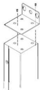
Install the screws (M4 X 6) in holes diagonal from each other.
Step 2 – PDU Mounting

natural_image
Technical line drawing of two vertical metal structural components with mounting holes and fasteners (no text or symbols)Install the PDU using fasteners compatible with the rack.
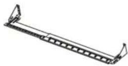
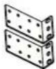
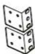
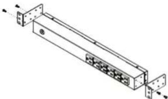
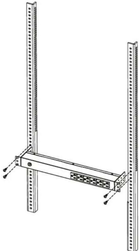
Vertical Installation with Brackets (0U models only)
Step 1 - Mounting bracket installation

natural_image
Technical line drawing of two mechanical components with fasteners and mounting holes (no text or symbols)Attach the Vertical Mounting Brackets to the PDU with the 4 supplied Bracket Mounting Screws (M4 X 6).
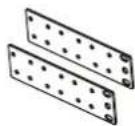
Step 2 – PDU Mounting
natural_image
Two vertical metal bars with textured ends, one extending to the right and the other to the left (no text or symbols)Install the PDU using fasteners compatible with the rack.
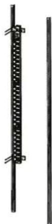
Vertical Installation with Keyhole Mounts (0U Models)
Step 1 – Keyhole Mount installation

natural_image
Technical line drawing of two mechanical components with pin holes (no text or symbols)Attach the Keyhole Mounting Pegs to the PDU with the 2 supplied Bracket Mounting Screws (M4 X 6).
Step 2 – PDU Mounting

Align the the Keyhole Mounts to the Keyhole Slots on the rack. Insert and slide down to lock firmly into place.
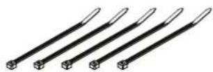
Cord Retention Tray installation (Optional for both horizontal and vertical installations)
Adjust the length of the Cord Retention Tray till the screw hole on the Tray and PDU are aligned.

natural_image
Technical line drawing of a mechanical device with a zoomed-in inset showing internal components (no text or symbols)Attach the Cord Retention Tray to the PDU with the 4 supplied Cord Retention Tray Mounting Screws (M3 X 6). Tighten the Cord Retention Tray with the screw on it.
natural_image
Technical line drawing of a multi-chamber electronic device with ports and connectors (no text or symbols)Use the Cable Ties provided to fasten each power cord to the Cord Retention Tray.
Meter Configuration

Depending on installation method (vertical or horizontal), the LED Meter may need to be rotated, before installation, for proper orientation.
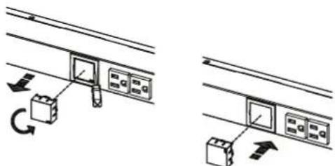
Use a screwdriver to gently remove the LED Meter. Rotate the LED Meter 90 degrees, and insert back into the PDU.
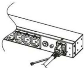
Locking Power Cord - For IEC Type PDU
Input Power Cord
Step 1. Align and insert the Cable Tie from the upper side of the Fixed Stand and fasten it as shown below.

natural_image
Technical line drawing of a mechanical assembly with mounting holes and a tool (no text or symbols)
natural_image
Technical line drawing of an electronic device with multiple ports and a connector (no text or symbols)Step 2. Align and insert the Cable Tie from the bottom side of the Fixed Stand and fasten it as shown below.
natural_image
Technical line drawing of a mechanical or electronic component with multiple ports and a central connector (no text or symbols)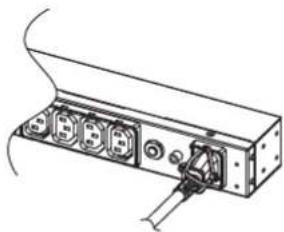
natural_image
Technical line drawing of an electronic device with multiple ports and a cable (no text or symbols)Output Power Cord
Step 1. Align and insert the Cable Tie from the upper side of the Fixed Stand and fasten it as shown below.

natural_image
Diagram of an electronic device with ports and cables, no visible text or symbols
natural_image
Technical line drawing of a device rear panel with ports and connectors (no text or symbols)Electrical Installation
Step 1 – Receptacle evaluation
Ensure that the plug type of your PDU unit (e.g. NEMA 5-15P, NEMA 5-20P, NEMA L5-30P) matches the wall receptacle type that you are using.

PDU must be plugged into a three-wire, grounded wall receptacle only. The wall receptacle must also be connected to an appropriate branch circuit/main with fuse or circuit breaker protection. Connection to any other type of wall receptacle may result in a shock hazard.
Step 2 – Plug the PDU into the wall receptacle

natural_image
Line drawing of a rack-mounted server unit with multiple ports and a cable connecting to a terminal outlet (no text or symbols)Step 3 – Attach equipment
Before attaching equipment, it is important to calculate the total load that you will be placing on the PDU. It is extremely important not to exceed the PDU's maximum current load (as outlined in the Specifications section). In order to determine your total load, simply add up the amperage of your devices and ensure that it does not exceed the unit's capacity.
natural_image
Line drawing of a rectangular electronic device with multiple ports and connectors (no text or symbols)Troubleshooting
| Problem Possible Cause Solution | ||
| PDU Outlets do not provide power to connected equipment | 1. Open breaker2. Loose power cord | Reset Breaker check if plug is completely connected.If the problem remains contact tech support. |
| Amperage displayed on Amperage Meter exceeds the unit's capability (Metered type only) | 1. Overload2. Amperage meter is damaged | Reduce the load on the PDU until the overload is gone.If the problem remains contact tech support. |
| Circuit breaker has tripped | 1. Sustained overload2. Excessive ambient or internal temperatures.3. Faulty breaker | Reset Breaker.If the problem remains contact tech support. |
Basic Series (1U)
Product Features
Front View
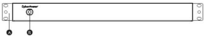
A. Mounting Bracket B. Circuit Breaker
Back View

A. Mounting Bracket
B. Back Outlets
C. External Site Ground
D. AC Power Cord
E. Screw Holes
Technical Specifications
| Model Name | PDU15B8RPDU15B10RPDU15B12R | PDU20B10R |
| Input | ||
| Voltage | 100 ~ 120 V | |
| Maximum Input Current | 12A UL (Derated) | 16A UL (Derated) |
| Circuit Breaker | 15 A | 20 A |
| Plug Type | NEMA 5-15P | NEMA 5-20P |
| Power Cord Length | 15 ft | |
| Output | ||
| Voltage | 100 ~ 120 V | |
| Maximum Output Current | 12A UL (Derated) | 16A UL (Derated) |
| Outlet Type(Quantity) | NEMA 5-15R(8)NEMA 5-15R(10)NEMA 5-15R(12) | NEMA 5-20R(10) |
| Physical | ||
| Dimension (HxWxD) | 1.75" x 17.5" x 1.5" / 4.45 x 44.5 x 3.81 cm | |
| Environmental | ||
| Humidity | 0 to 95% Non-condensing | |
| Altitude | 13100 ft / 4000m | |
| Temperature | 32°F to 122°F / 0°C to 50°C | |
| Safety Approvals | ||
| Certifications | UL62368, UL60950-1, RoHS | |
Basic Series (1U)
Product Features
Front View
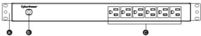
B. Circuit Breaker C. Front Outlets A. Mounting Bracket
Back View
A. Mounting Bracket
B. Back Outlets
C. External Site Ground
D. AC Power Card
E. Cord Retention Tray Screw Holes
Technical Specifications
| Model Name | PDU15B2F8RPDU15B2F10RPDU15B2F12RPDU15B4F12RPDU15B6F8RPDU15B6F12R |
| Input | |
| Voltage | 100 ~ 120 V |
| Maximum Input Current | 12A UL (Derated) |
| Circuit Breaker | 15 A |
| Plug Type | NEMA 5-15P |
| Power Cord Length | 15 ft |
| Output | |
| Voltage | 100 ~ 120 V |
| Maximum Output Current | 12A UL (Derated) |
| Outlet Type(Quantity) | NEMA 5-15R(10)NEMA 5-15R(12)NEMA 5-15R(14)NEMA 5-15R(16)NEMA 5-15R(14)NEMA 5-15R(18) |
| Physical | |
| Dimension (HxWxD) | 1.75" x 17.5" x 2.25" / 4.45 x 44.5 x 5.72 cm |
| Environmental | |
| Humidity | 0 to 95% Non-condensing |
| Altitude | 13100 ft / 4000m |
| Temperature | 32°F to 122°F / 0°C to 50°C |
| Safety Approvals | |
| Certifications | UL62368, UL60950-1, RoHS |
Basic Series (1U)
Product Features
Front View
A. Mounting Bracket
Back View
Twist Type
A. Mounting Bracket
B. Back Outlets (IEC 320 C13)
C. Back Outlets (IEC 320 C19)
D. Circuit Breaker
E. External Site Ground
F. AC Power Cord
G. Cord Retention Tray Screw Holes
IEC Type
A. Mounting Bracket
B. Back Outlets (IEC 320 C13)
C. Circuit Breaker
D. External Site Ground
E. AC Inlet (IEC 320 C20)
F. Cord Retention Tray Screw Holes
Technical Specifications
| Model Name | PDU20BHVT8RPDU20BHVT12R | PDU20BHVIC8RPDU20BHVIC12R | PDU20BHVCEE8RPDU20BHVCEE12R |
| Input | |||
| Voltage | 200~240V | ||
| Maximum Input Current | 16A CE, UL (Derated) | ||
| Circuit Breaker | 20 A | ||
| Plug Type | NEMA L6-20P IEC 320 C20 | IEC 309 16A | |
| Power Cord Length | 10 ft | ||
| Output | |||
| Voltage | 200~240V | ||
| Maximum Output Current | 16A CE, UL (Derated) | ||
| Outlet Type(Quantity) | IEC 320 C19(2)/C13(6)IEC 320 C13(12) | ||
| Physical | |||
| Dimension (HxWxD) | 1.75" x 17.5" x 1.5" / 4.45 x 44.5 x 3.81 cm | ||
| Environmental | |||
| Humidity | 0 to 95% Non-condensing | ||
| Altitude | 13100 ft / 4000m | ||
| Temperature | 32°F to 122°F / 0°C to 50°C | ||
| Safety Approvals | |||
| Certifications | UL62368UL60950-1RoHS | UL62368UL60950-1RoHS, CE | CE |
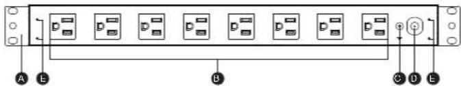
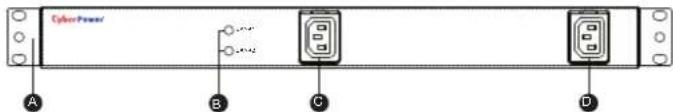
Basic Series (1U)
Product Features
Front View
Normal Type
A. Mounting Bracket
B. LED Indicators
C. Front Bank 1 Outlets
High Voltage Type
A. Mounting Bracket B. LED Indicators C. Front Bank 1 Outlets
D. Front Bank 2 Outlets
Back View
Normal Type
A. Mounting Bracket
B. Circuit Breaker (Bank 1)
C. Rear Bank 2 Outlets
D. External Site Ground
E. Circuit Breaker (Bank 2)
F. AC Power Cord
G. Cord Retention Tray
Screw Holes
High Voltage Type

A. Mounting Bracket
B. Rear Bank 2 Outlets
C. Rear Bank 1 Outlets
D. Circuit Breaker (Bank 2)
E. Circuit Breaker (Bank 1)
F. External Site Ground
G. AC Power Cord
H. Cord Retention Tray
Screw Holes
Technical Specifications
| Model Name | PDU30BT8F8RPDU30BT10F10R | PDU30BHVT2F6RPDU30BHVT4F8R |
| Input | ||
| Voltage | 100~120 V 200~240 V | |
| Maximum Input Current | 24A UL (Derated) | |
| Circuit Breaker | 20A x 2 | |
| Plug Type | NEMA L5-30P | NEMA L6-30P |
| Power Cord Length | 12 ft | 10 ft |
| Output | ||
| Voltage | 100~120 V | 200~240 V |
| Maximum Output Current | 24A UL (Derated) | |
| Maximum Output Current | 16A (per bank) | 20A (per bank) |
| Outlet Type(Quantity) | NEMA 5-20R(16)NEMA 5-20R(20) | IEC 320 C19(2)/C13(6)IEC 320 C13(12) |
| Indicators | ||
| LED Indicators | Bank1(GREEN)、Bank2(GREEN) | |
| Physical | ||
| Dimension (HxWxD) | 1.75" x 17.5" x 2.25" / 4.45 x 44.5 x 5.72 cm | |
| Environmental | ||
| Humidity | 0 to 95% Non-condensing | |
| Altitude | 13100 ft / 4000m | |
| Temperature | 32°F to 122°F/0°C to 50°C | 32°F to 140°F/0°C to 60°C |
| Safety Approvals | ||
| Certifications | UL62368, UL60950-1, RoHS | |
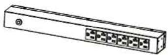
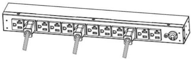
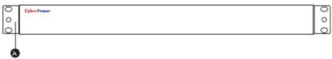
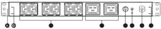
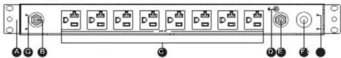
Basic Series (0U)
Product Features
Front View Back View
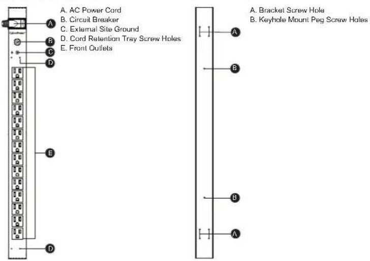
Technical Specifications
| Model Name | PDU15BV14F PDU20BVT14F PDU20BV32F | ||
| Input | |||
| Voltage | 100~120V | ||
| Maximum Input Current | 12A UL (Derated) | 16A UL (Derated) | |
| Circuit Breaker | 15 A | 20 A | |
| Plug Type | NEMA 5-15P | NEMA L5-20P | NEMA 5-20P |
| Power Cord Length | 10ft | ||
| Output | |||
| Voltage | 100~120V | ||
| Maximum Output Current | 12A UL (Derated) | 6A UL (Derated) | |
| Outlet Type(Quantity) | NEMA 5-15R(14) | NEMA 5-20R(14) | NEMA 5-20R(32) |
| Physical | |||
| Dimension (HxWxD) | 24" x 1.75" x 1.5" /60.96 x 4.45 x 3.81 cm | 70" x 1.75" x 1.5" /177.80 x 4.45 x 3.81 cm | |
| Environmental | |||
| Humidity | 0 to 95% Non-condensing | ||
| Altitude | 13100 ft / 4000m | ||
| Temperature | 32°F to 122°F / 0°C to 50°C | ||
| Safety Approvals | |||
| Certifications | UL62368, UL60950-1, RoHS | ||
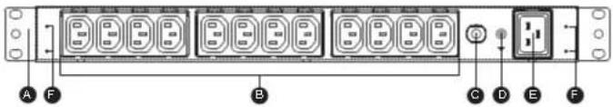
Basic Series (0U)
Product Features
Front View Back View

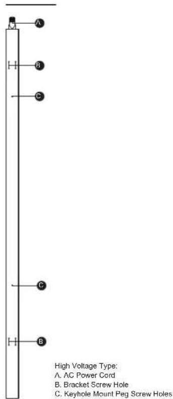
Technical Specifications
| Model Name | PDU30BVHVT32F |
| Input | |
| Voltage | 200~240V |
| Maximum Input Current | 24A UL (Derated) |
| Circuit Breaker | 20 A x 2 |
| Plug Type | NEMA L6-30P |
| Power Cord Length | 10 ft |
| Output | |
| Voltage | 200~240V |
| Maximum Output Current | 24A UL (Derated) |
| Maximum Output Current | 20A (per bank) |
| Outlet Type(Quantity) | IEC 320 C19(8)/C13(24) |
| Physical | |
| Dimension (HxWxD) | 60" x 1.75" x 2.25" / 152.40 x 4.45 x 5.72 cm |
| Environmental | |
| Humidity | 0 to 95% Non-condensing |
| Altitude | 13100 ft / 4000m |
| Temperature | 32°F to 140°F / 0°C to 60°C |
| Safety Approvals | |
| Certifications | UL62368, UL60950-1, RoHS |
Metered Series (1U)
Product Features
Front View
A. Mounting Bracket
B. Circuit Breaker
A. Mounting Bracket
B. Back Outlets
C. External Site Ground
D. AC Power Cord
E. Cord Retention Tray Screw Holes
Technical Specifications
| Model Name | PDU15M2F8RPDU15M2F10RPDU15M2F12R | PDU20M2F8RPDU20M2F10RPDU20M2F12R | PDU20MT2F10R |
| Input | |||
| Voltage | 100~120V | ||
| Maximum Input Current | 12A UL (Derated) | 16A UL (Derated) | |
| Circuit Breaker | 15 A | 20 A | |
| Plug Type | NEMA 5-15P | NEMA 5-20P | NEMA L5-20P |
| Power Cord Length | 15ft | ||
| Output | |||
| Voltage | 100~120V | ||
| Maximum Output Current | 12A UL (Derated) | 16A UL (Derated) | |
| Outlet Type(Quantity) | NEMA 5-15R(10)NEMA 5-15R(12)NEMA 5-15R(14) | NEMA 5-20R(10)NEMA 5-20R(12)NEMA 5-20R(14) | NEMA 5-20R(12) |
| Indicators | |||
| Meter Readout | Amperage | ||
| Physical | |||
| Dimension (HxWxD) | 1.75" x 17.5" x 2.25" / 4.45 x 44.5 x 5.72 cm | ||
| Environmental | |||
| Humidity | 0 to 95% Non-condensing | ||
| Altitude | 13100 ft / 4000m | ||
| Temperature | 32°F to 122°F / 0°C to 50°C | ||
| Safety Approvals | |||
| Certifications | UL62368, UL60950-1, FCC Class A, RoHS | ||
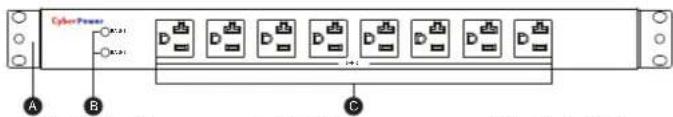
Metered Series (0U)
Product Features

Technical Specifications
| Model Name | PDU15MV20FPDU15MV32F | PDU20MV20FPDU20MV32F | PDU20MVT20F |
| Input | |||
| Voltage | 100~120V | ||
| Maximum Input Current | 12A UL (Derated) | 16A UL (Derated) | |
| Circuit Breaker | 15 A | 20 A | |
| Plug Type | NEMA 5-15P | NEMA 5-20P NEMA L5-20P | |
| Power Cord Length | 10ft | ||
| Output | |||
| Voltage | 100~120V | ||
| Maximum Output Current | 12A UL (Derated) | 16A UL (Derated) | |
| Outlet Type(Quantity) | NEMA 5-15R(20)NEMA 5-15R(32) | NEMA 5-20R(20)NEMA 5-20R(32) | NEMA5-20R(20) |
| Indicators | |||
| Meter Readout | Amperage | ||
| Physical | |||
| Dimension (HxWxD) | 48" x 1.75" x 2.25"/ 121.92 x 4.45 x 5.72 cm70" x 1.75" x 2.25"/ 177.80 x 4.45 x 5.72 cm | 48" x 1.75" x2.25"/ 121.92 x 4.45 x 5.72 cm | |
| Environmental | |||
| Humidity | 0 to 95% Non-condensing | ||
| Altitude | 13100 ft / 4000m | ||
| Temperature | 32°F to 122°F / 0°C to 50°C | ||
| Safety Approvals | |||
| Certifications | UL62368, UL60950-1, FCC Class A, RoHS | ||
Metered Series (0U)
Product Features
Front View Back View
Technical Specifications
| Model Name | PDU20MVHVT20FPDU20MVHVT30FPDU20MVHVT38F | PDU20MVHVIEC20FPDU20MVHVIEC30FPDU20MVHVIEC38F | PDU20MVHVCEE20FPDU20MVHVCEE30FPDU20MVHVCEE38F |
| Input | |||
| Voltage | 200~240V | ||
| Maximum Input Current | 16A CE, UL (Derated) | ||
| Circuit Breaker | 20 A | ||
| Plug Type | NEMA L6-20P | IEC 320 C20 IEC | 309 16A |
| Power Cord Length | 10 ft | ||
| Output | |||
| Voltage | 200~240V | ||
| Maximum Output Current | 16A CE, UL (Derated) | ||
| Outlet Type(Quantity) | IEC 320 C19(4)/C13(16)IEC 320 C19(6)/C13(24)IEC 320 C19(8)/C13(30) | ||
| Indicators | |||
| Meter Readout | Amperage | ||
| Physical | |||
| Dimension (HxWxD) | 48" x 1.75" x 1.5" / 121.92 x 4.45 x 3.81 cm60" x 1.75" x 1.5" / 152.40 x 4.45 x 3.81 cm70" x 1.75" x 1.5" / 177.80 x 4.45 x 3.81 cm | ||
| Environmental | |||
| Humidity | 0 to 95% Non-condensing | ||
| Altitude | 13100 ft / 4000m | ||
| Temperature | 32°F to 122°F / 0°C to 50°C | ||
| Safety Approvals | |||
| Certifications | UL62368,UL60950-1FCC Class A,RoHS | UL62368,UL60950-1FCC Class A,RoHS, CE | CE |
Meter Series (0U)
Product Features
Technical Specifications
| Model Name | PDU30MVT24FPDU30MVT32F | PDU30MVHVT20FPDU30MVHVT30FPDU30MVHVT38F |
| Input | ||
| Voltage | 200~240V100~120V | |
| Maximum Input Current | 24A UL (Derated) | |
| Circuit Breaker | 20A x 2 | |
| Plug Type | NEMA L5-30P | NEMA L6-30P |
| Power Cord Length | 10ft | |
| Output | ||
| Voltage | 200~240V100~120V | |
| Maximum Output Current | 24A UL (Derated) | |
| Maximum Output Current | 20A (per bank)16A (per bar | |
| Outlet Type(Quantity) | NEMA 5-20R(24)NEMA 5-20R(32) | IEC 320 C19(4)/C13(16)IEC 320 C19(6)/C13(24)IEC 320 C19(8)/C13(30) |
| Indicators | ||
| Meter Readout | Amperage x 2 | |
| Physical | ||
| Dimension (WxDxH) | 60° x 1.75° x 2.25° / 152.40 x 4.45 x 5.72 cm70° x 1.75° x 2.25° / 177.80 x 4.46 x 5.72 cm | 48° x 1.75° x 2.25° / 121.92 x 4.46 x 5.72 cm60° x 1.75° x 2.25° / 152.40 x 4.46 x 5.72 cm70° x 1.75° x 2.25° / 177.80 x 4.45 x 5.72 cm |
| Environmental | ||
| Humidity | 0 to 95% Non-condensing | |
| Altitude | 13100 ft / 4000m | |
| Temperature | 32°F to 122°F / 0°C to 50°C 32°F to 140°F / 0°C to 60°C | |
| Safety Approvals | ||
| Certifications | UL62368, UL60950-1, FCC Class A, RoHS | |
Conformance Approvals
FCC Warning
WARNING!! Changes or modifications to this unit not expressly approved by the party responsible for compliance could void the user's authority to operate the equipment.
WARNING!! This equipment has been tested and found to comply with the limits for a Class A Digital Device, pursuant to Part 15 of the FCC Rules. These limits are designed to provide reasonable protection against harmful interference when the equipment is operated in a commercial environment. This equipment generates, uses and can radiate radio frequency energy and, if not installed and used in accordance with the instruction manual, may cause harmful interference to radio communications. Operation of this equipment in a residential area is likely to cause harmful interference in which case the user will be required to correct the interference at his own expense.
However, there is no guarantee that interference will not occur in a particular installation. If this equipment does cause harmful interference to radio or television reception, which can be determined by turning the equipment off and on, the user is encouraged to try to correct the interference by one or more of the following measures:
- Reorient or relocate the receiving antenna.
- Increase the separation between the equipment and receiver.
- Connect the equipment into an outlet on a circuit different from that to which the receiver is connected.
- Consult the dealer or an experienced radio/TV technician for help.
Notice: (1) An unshielded-type power cord is required in order to meet FCC emission limits and also to prevent interference to the nearby radio and television reception. It is essential that only the supplied power cord by used. (2) Use only shielded cables to connect I/O devices to this equipment.
Note: THE MANUFACTURER IS NOT RESPONSIBLE FOR ANY RADIO OR TV INTERFERENCE CAUSED BY UNAUTHORIZED MODIFICATIONS TO THIS EQUIPMENT. SUCH MODIFICATIONS COULD VOID THE USER'S AUTHORITY TO OPERATE THE EQUIPMENT.
The Class A digital apparatus meets all requirements of the Canadian Interference-Causing Equipment Regulation.
This is a class A product. In a domestic environment this product may cause radio interference in which case the user may be required to take adequate measures.
⚠ WARNING: This product can expose you to chemicals including Styrene, which is known to the State of California to cause cancer, and Bisphenol-A, which is known to the State of California to cause birth defects or other reproductive harm. For more information go to www.P65Warnings.ca.gov.
Customer Service & Warranty
Product Registration
Thank you for purchasing a CyberPower product. Prompt product registration entitles coverage under the Limited Warranty and also allows the opportunity to be notified of product enhancements, upgrades, and other announcements.
Registration is quick and easy at www.cyberpowersystems.com/registration (for USA and Canada) or www.cyberpower.com/registration (for all other regions).
Cyber Power International
Feel free to contact our Tech Support department with installation, troubleshooting, or general product questions.
Cyber Power Systems, Inc.
Web: www.cyberpower.com
For USA and Canada:
4241 12th Ave East, Suite 400 Shakopee, MN55379 Toll-free: (877) 297-6937
For all other regions:
Please visit our website for local contact information.
Limited Warranty
Read the following terms and conditions carefully before using the CyberPower PDU series. By using the Product, you consent to be bound by and become a party to the terms and conditions of this Limited Warranty. If you do not agree to the terms and conditions of this Warranty, you should return the Product for a full refund prior to using it.
Who Is Providing This Warranty?
CyberPower Systems, Inc. provides this Limited Warranty.
What Does This Warranty Cover?
This warranty covers defects in materials and workmanship in the Product under normal use and conditions.
What Is the Period of Coverage?
For USA and Canada, CyberPower provides a 3-Year warranty to the original purchaser who owns the Product. For other regions, please contact your local CyberPower sales team for more information.
Who Is Covered?
This warranty only covers the original purchaser. Coverage ends if you sell or otherwise transfer the Product.
How Do You Get Service?
- You can use the contact information mentioned above for instructions.
- When you contact CyberPower, identify the Product and the Purchase Date.
- You must provide a purchase receipt (or other proof of the original purchase) and provide a description of the defect.
What Will We Do To Correct Problems?
CyberPower will inspect and examine the Product. If the Product is defective in material or workmanship, CyberPower will repair or replace it at CyberPower's expense, or, if CyberPower is unable to or decides not to repair or replace the Product (if defective) within a reasonable time, CyberPower will refund to you the full purchase price you paid for the Product (purchase receipt showing price paid is required).
Who Pays for Shipping?
We pay when we send items to you; you pay when you send items to us.
What Are Some Things This Warranty Does Not Cover?
- This Warranty does not cover any software that is damaged or needs to be replaced due to the failure of the Product or any data that is lost as a result of the failure or the restoration of data or records, or the re-installation of software.
- This Warranty does not cover or apply to: misuse, modification, operation or storage outside environmental limits of the Product or the equipment connected to it, nor for damage while in transit or in storage, nor if there has been improper operation or maintenance, or use with items not designed or intended for use with the Product, such as laser printers, appliances, aquariums, medical or life support devices, etc.
What are the Limitations?
- This Warranty does not apply unless the Product and the equipment that was connected to it were connected to properly wired and grounded outlets (including compliance with electrical and safety codes of the most current electrical code), without the use of any adapters or other connectors.
- The Product must have been plugged directly into the power source and the equipment connected to the Product must be directly connected to the Product and not "daisy-chained" together in serial fashion with any extension cords, another Product or device similar to the Product, surge suppressor, or power tap. Any such installation voids the Limited Warranty.
- The Product and equipment connected to it must have been used properly in a suitable and proper environment and in conformance with any license, instruction manual, or warnings provided with the Product and the equipment connected to it.
- The Product must have been used at all times within the limitations on the Product's VA capacity.
- The sole and exclusive remedies of the Initial Customer are those provided by this Warranty.
CyberPower®
Cyber Power Systems, Inc.
www.cyberpower.com


- Table of Contents
- Product Features
- Model List:
- PDU Naming Convention:
- Package Contents
- Safety Precautions
- Read the following before installing or operating the Power Distribution Unit (PDU):
- Horizontal Installation (1U models only)
- Vertical Installation with Brackets
- Vertical Installation with Brackets (0U models only)
- Vertical Installation with Keyhole Mounts (0U Models)
- Cord Retention Tray installation (Optional for both horizontal and vertical installations)
- Meter Configuration
- Locking Power Cord - For IEC Type PDU
- Electrical Installation
- Basic Series (1U)
- Technical Specifications
- Basic Series (0U)
- Metered Series (1U)
- Metered Series (0U)
- Meter Series (0U)
- Conformance Approvals
- FCC Warning
- Customer Service & Warranty
- Product Registration
- Cyber Power International
- For USA and Canada:
- For all other regions:
- Limited Warranty
- Who Is Providing This Warranty?
- What Does This Warranty Cover?
- What Is the Period of Coverage?
- Who Is Covered?
- How Do You Get Service?
- What Will We Do To Correct Problems?
- Who Pays for Shipping?
- What Are Some Things This Warranty Does Not Cover?
- What are the Limitations?
- CyberPower®
Brand : CyberPower
Model : PDU15BV14F
Category : Surge protector power strip