
FlexNetwork HSR6800 - Network HP - Free user manual and instructions
Find the device manual for free FlexNetwork HSR6800 HP in PDF.

| Product Type | Power Module for HP FlexNetwork HSR6800 Routers |
| Model Numbers | PSR1200-A (AC input), PSR1200-D (DC input) |
| Rated Input Voltage (AC) | 100 to 240 VAC (50/60 Hz) |
| Rated Input Voltage (DC) | -48 VDC to -60 VDC |
| Rated Output Voltage | 12 V and 3.3 V |
| Maximum Output Power | 1213 W |
| Maximum Input Current (AC) | 16 A |
| Maximum Input Current (DC) | 42 A |
| Maximum Output Current (12 V) | 100 A |
| Maximum Output Current (3.3 V) | 4 A |
| Dimensions (H × W × D) | 40.5 × 140 × 340.4 mm (1.59 × 5.51 × 13.4 in) |
| Operating Temperature | -10°C to +50°C (-14°F to +122°F) |
| Storage Temperature | -40°C to +70°C (-40°F to +158°F) |
| Protection Functions | Under-voltage input, over-voltage input, over-voltage output, output short circuit, under-current output, over-current output, and overheat |
| Hot Swapping | Supported |
| Redundancy Support | N+1 or N+N redundant mode |
| Status LED | Green (operational), Red (fault), OFF (input fault or power off) |
| Power Switch | Yes, on front panel |
| Compatibility | HP 6600 and HSR6800 series (PSR1200-A and PSR1200-D only; cannot mix with other models) |
Frequently Asked Questions - FlexNetwork HSR6800 HP
User questions about FlexNetwork HSR6800 HP
0 question about this device. Answer the ones you know or ask your own.
Ask a new question about this device
Download the instructions for your Network in PDF format for free! Find your manual FlexNetwork HSR6800 - HP and take your electronic device back in hand. On this page are published all the documents necessary for the use of your device. FlexNetwork HSR6800 by HP.
USER MANUAL FlexNetwork HSR6800 HP
HP 6600/HSR6800 Routers
AC1200 & DC1200 Power Modules
User Guide
Legal and notice information
© Copyright 2014 Hewlett-Packard Development Company, L.P.
No part of this documentation may be reproduced or transmitted in any form or by any means without prior written consent of Hewlett-Packard Development Company, L.P.
The information contained herein is subject to change without notice.
HEWLETT-PACKARD COMPANY MAKES NO WARRANTY OF ANY KIND WITH REGARD TO THIS MATERIAL, INCLUDING, BUT NOT LIMITED TO, THE IMPLIED WARRANTIES OF MERCHANTABILITY AND FITNESS FOR A PARTICULAR PURPOSE. Hewlett-Packard shall not be liable for errors contained herein or for incidental or consequential damages in connection with the furnishing, performance, or use of this material.
The only warranties for HP products and services are set forth in the express warranty statements accompanying such products and services. Nothing herein should be construed as constituting an additional warranty. HP shall not be liable for technical or editorial errors or omissions contained herein.
Contents
Power module overview 1
Front panel 2
Technical specifications 4
Status LED 4
Power module configuration 7
Installing a power module 8
Installing an AC power module and connecting the power cord10
Installing the AC power module 10
Connecting the AC power cord 12
Installing a DC power module and connecting the power cord·13
Installing a DC power module 13
Connecting the DC power cords.... 14
Replacing a power module 17
Remove the AC power cord 17
Remove the DC power cords 18
Remove the DC power module 19
Support and other resources 21
Contacting HP 21
Subscription service 21
Related information 22
Documents 22
Websites 22
Conventions 22
Power module overview
In the following tabel, "Yes" means "Supported" and "No" means "Not supported."
| Product number | Power module | 6600 | HSR6600 | HSR6800 |
| JG335A | PSR1200-A | Yes | No | Yes |
| JG334A | PSR1200-D | Yes | No | Yes |
The PSR1200-A is a built-in power module with AC input and DC output, and the PSR1200-D is a built-in power module with DC input and DC output. The maximum output power of each power module is 1200W.
| Feature | Description |
| Protection function | Protection for under-voltage input, over-voltage input, over-voltage output, output short circuit, under-current output, over-current output, and overheat. |
| Support for hot swapping | You can plug or unplug the power module when the device is operating properly. |
| Support for redundancy | The power modules can work in N+1 or N+N redundant mode. For more information, see “Power module configuration.” |
Front panel
Figure 1 Front panel of PSR1200-A

(1) Status LED (2) Power module handle
(3) Captive screw (4) Power switch
(5) Power socket
Figure 2 Front panel of PSR1200-D
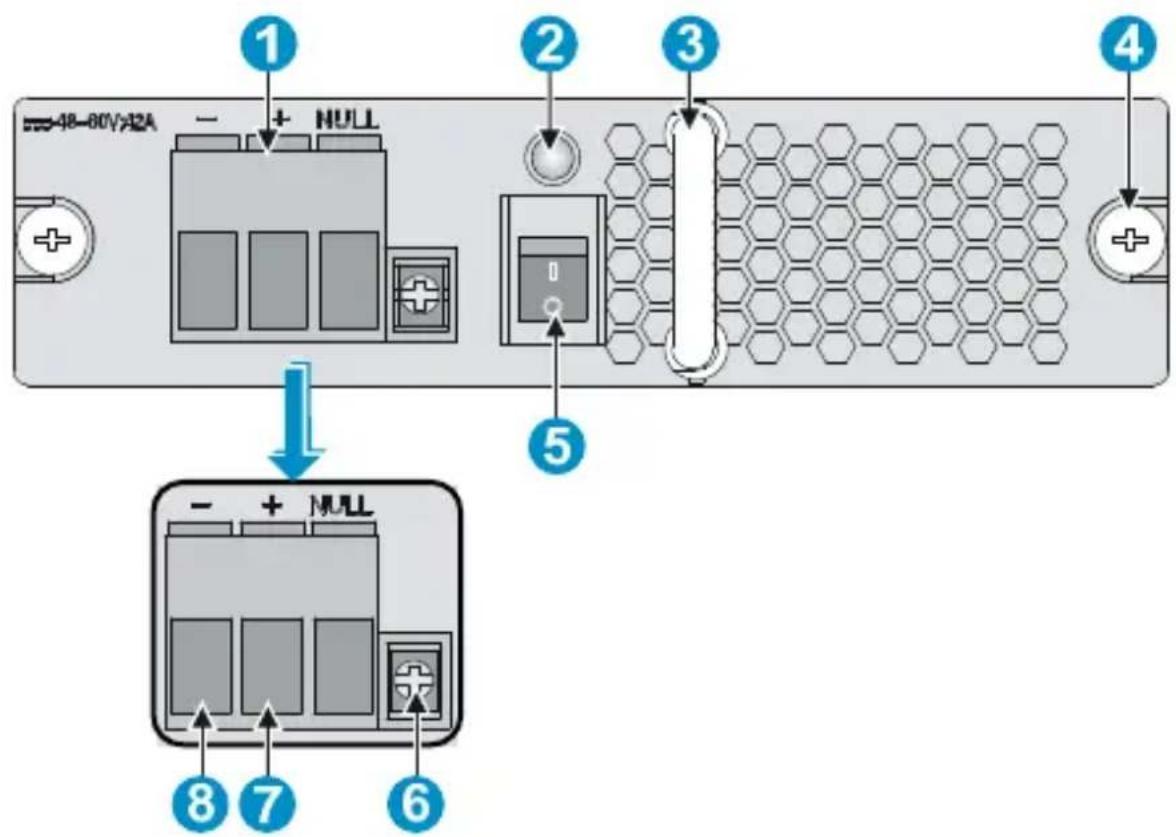
(1) Power source connector (2) Status LED
(3) Power module handle (4) Captive screw
(5) Power switch (6) Fastening screw hole
(7) Positive (+) terminal of DC input
(8) Negative (−) terminal of DC input
Technical specifications
Table 1 Technical specifications for the PSR1200-A and PSR1200-D
| Item | PSR1200-A | PSR1200-D | |
| Rated input voltage | 100 to 240 VAC(50/60 Hz) | -48 VDC to-60 VDC | |
| Rated output voltage 12 V and 3.3 V | |||
| Maximum input current 16 A 42 A | |||
| Maximum output current | 100 A (12 V AC)4 A (3.3 V AC) | ||
| Maximum output power 1213 W | |||
| Dimensions (H × W × D) | 40.5 × 140 × 340.4 mm (1.59 × 5.51 × 13.4 in) | ||
| Ambient temperature | Operating temperature | -10°C to +50°C (-14°F to +122°F) | |
| Storage temperature | -40°C to +70°C (-40°F to +158°F) | ||
Status LED
The PSR1200-A and PSR1200-D have only one status LED. Table 2 describes its colors and working status.
Table 2 Description of LEDs on the PSR1200-A and PSR1200-D
| Color/status | Meaning | Possible | causes |
| Green | The power module is operational. | — | |
| Red | The power module is faulty. | Power alarm (input under-voltage, output short circuit, output over-current, output over-voltage, or overheat occurred to the power module, and the power module took a self-protection action). | |
| The power module fan is faulty. | |||
| OFF | The power input is faulty. | The power switch is off. | |
| The power cable is connected incorrectly. | |||

CAUTION:
- When the status LED is red, check whether the power module has encountered the following failures: output short circuit, output over-current, output over-voltage, or overheat. If you have detected and removed the output short circuit, output over-current, or overheat failures, the power module automatically restores. However, if the power module encounters the output over-voltage failures, the power module will enter the deadlock sate, and cannot automatically restore after you remove the failures. To restore the power module in the deadlock state, turn off the power switch, unplug the power cord, plug the power cord, and then turn on the power switch.
- Do not frequently turn on and turn off the power module. The interval between each turning on and turn off operation should be longer than 30 seconds.
- After the circuit breaker that connects to a power module is off, it is normal that the LEDs on the power module last on for a while.
Power module configuration
You can determine the number of power modules to be configured for the system according to the actual power consumption and power supply conditions.
- In an environment with two power sources, you can configure N+N redundant mode.
- In an environment with only one power source, you can configure N+1 or N+N redundant mode.
- For easy usage and maintenance, be sure to configure a proper circuit breaker for each power input. The rated current of the circuit breaker must be more than 25 A.
NOTE:
In the term N+1 and N+N , the value of N depends on the number of power module slots in the device. N+1 or N+N must not be more than the total number of power module slots.
Installing a power module

CAUTION:
- PSR1200-A and PSR1200-D cannot work with other models of power modules in the same device, and the PSR1200-A and PSR1200-D cannot work together in the same device.
- When the temperature of the power module is higher than the upper limit of the operating temperature, the power module automatically shuts down. When the temperature falls into the normal range, the power module automatically starts.
Figure 3 illustrates the flow for installing a power module. Strictly follow the sequence to avoid possible dangers.
Figure 3 Installation flow of a power module
![graph TD A["Remove the Blank panel"] --> B["Install the power module"] B --> C["Connect the power cord"] C --> D["Turn on the circuit breaker"] D --> E["Turn on the power switch"]](/content/2026/06/1201913/images/2a3e2aeb2a8c9dc117a5113e137675caa24c5b3da0cd5e2c055463f21fd3f420.jpg)
NOTE:
The device needs at least one power module to provide power supply, so the chassis has a power module slot without a blank panel. For this slot, you can skip “Remove the blank panel” in the figure above.
Before the installation, prepare the following tools.
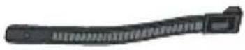 cable tie cable tie | 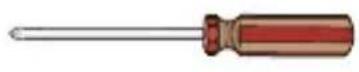 #1 Phillips screwdriver #1 Phillips screwdriver |
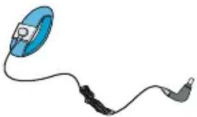 ESD-preventive wrist strap ESD-preventive wrist strap |  Marker Marker |
Installing an AC power module and connecting the power cord
Installing the AC power module
Follow these steps to install the AC power module:
- Wear an ESD-preventive wrist strap, and make sure that the wrist strap makes good skin contact and is properly grounded.
- Use the Phillips screwdriver to loosen the captive screws on the blank panel, and remove the blank panel from the slot to be used.
Figure 4 Remove the blank panel
- Unpack the power module.
- Put the power module to the correct position. Holding the power module handle with one hand and supporting the power module bottom with the other hand, plug the power module into the slot along the slide rails.
- Use the Phillips screwdriver to fasten the captive screws on the power module until the power module is fixed to the chassis.
Figure 5 Install the AC power module
Connecting the AC power cord

WARNING!
• Make sure that each power cord has a separate circuit breaker.
• Turn off the circuit breaker before connecting the power cord.
Follow these steps to connect the AC power cord:
- Make sure the power switch is in the OFF position.
- Plug one end of the power cable shipped with the device into the power socket.
- Fix the power cord to the power module handle by using a cable tie.
Figure 6 Connect and fix the power cord

-
Plug the other end into the AC power socket of the AC power source, and turn on the circuit breaker of the power cord.
-
Turn on the power switch, and check that the status LED is ON. It indicates that the power cord is correctly connected. If the status LED is OFF, troubleshoot the installation process until the status LED is ON.
Installing a DC power module and connecting the power cord
Installing a DC power module
Follow these steps to install a DC power module:
- Wear an ESD-preventive wrist strap, and make sure that the wrist strap makes good skin contact and is properly grounded.
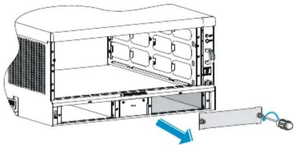
- Use the Phillips screwdriver to loosen the captive screws on the blank panel, and remove the blank panel from the slot to be used, as shown in Figure 4
- Unpack the DC power module, and mark the positive terminal and negative terminal of the power module according to the marks on the power module panel.
- Use the Philips screwdriver to loosen the captive screws at the right side of the power source connector, remove the power source connector from the power module, and keep it for future use.
Figure 7 Remove the power source connector from the power module

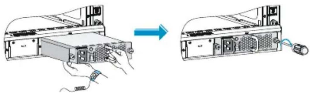
- Put the power module to the correct position. Holding the power module handle with one hand and supporting the power module bottom with the other hand, plug the power module into the slot along the slide rails.
- Use the Phillips screwdriver to fasten the captive screws on the power module until the power module is fixed to the chassis.
Figure 8 Install the DC power module

Connecting the DC power cords
Figure 9 Connect the DC power cords

Follow these steps to connect the DC power cords:
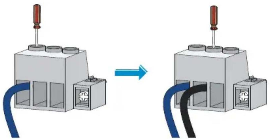
-
Plug one end of the shipped DC power cord marked with “-”, a blue power cord, into the terminal marked with “-”, and fasten the screw to fix the cord.
-
Plug one end of the shipped DC power cord marked with “+”, a black power cord, into the terminal marked with “+”, and fasten the screw to fix the cord.
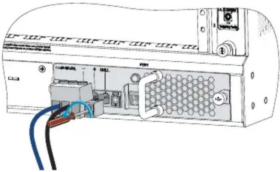
Figure 10 Connect the DC power cords to the power source connector
- Put the power source connector to a correct position, plug the power source connector into the DC power module, and use the Philips screwdriver to fasten the captive screw at the right side to fix the power source connector to the power module.
Figure 11 plug the power source connector into the DC power module

- Plug the other end into the DC power source, and turn on the circuit breaker of the power cord.
- Turn on the power switch, and check that the status LED is ON. It indicates that the power cord is correctly connected. If the status LED is OFF, troubleshoot the installation process until the status LED is ON.
Replacing a power module
Figure 12 illustrates the flow for replacing a power module. Strictly follow the sequence to avoid possible dangers.
Figure 12 Replacement flow of a power module
![graph TD A["Turn off the power switch"] --> B["Turn off the circuit breaker"] B --> C["Remove the power cord"] C --> D["Remove the power module"] D --> E["Install another power module"]](/content/2026/06/1201913/images/5b3cac26efe90b22b7f0f800ebdfd90e3a51f26090e3e2988996bf5f323c587b.jpg)
Before replacing a power module, prepare an ESD-preventive wrist strap and a #1 Phillips screwdriver.
Remove the AC power cord
Follow these steps to remove the AC power cord:
- Wear an ESD-preventive wrist strap, and make sure that the wrist strap makes good skin contact and is properly grounded.
- Turn off the power switch.
- Turn off the circuit breaker of the power cord.
- Loosen the cable tie that fixes the power cord to the power module handle, and unplug the AC power cord connector.

CAUTION:
After the circuit breaker that connects to a power module is off, it is normal that the LEDs on the power module last on for a while.
Remove the DC power cords
Follow these steps to remove the DC power cords:
- Wear an ESD-preventive wrist strap, and make sure that the wrist strap makes good skin contact and is properly grounded.
- Turn off the power switch.
- Turn off the circuit breaker of the power cord.
- Use the Philips screwdriver to loosen the captive screw at the right side of the power source connector, and pull the power source connector out together with the DC power cords.
Figure 13 Remove the DC power cords
Remove the DC power module
Follow these steps to remove the DC power module:
- Use the Phillips screwdriver to loosen the captive screws on the power module.
- Grasping the handle of the power module with one hand, pull the power module part way out. Grasping the handle of the power module with one hand and supporting the bottom of the power module with the other hand, pull the module slowly along the guide rails out of the slot.
Figure 14 Remove the DC power module

-
Put the power module on an antistatic mat.
-
Plug a new DC power module into the slot, and use the Philips screwdriver to fasten the captive screws on both sides of the power module.

CAUTION:
Before plugging a removed power module into a power module slot, make sure that the LED on the power module is off.
Support and other resources
Contacting HP
For worldwide technical support information, see the HP support website:
http://www.hp.com/support
Before contacting HP, collect the following information:
• Product model names and numbers
• Technical support registration number (if applicable)
• Product serial numbers
- Error messages
- Operating system type and revision level
• Detailed questions
Subscription service
HP recommends that you register your product at the Subscriber's Choice for Business website:
http://www.hp.com/go/wwalerts
After registering, you will receive email notification of product enhancements, new driver versions, firmware updates, and other product resources.
Related information
Documents
To find related documents, browse to the Manuals page of the HP Business Support Center website:
http://www.hp.com/support/manuals
- For related documentation, navigate to the Networking section, and select a networking category.
- For a complete list of acronyms and their definitions, see HP FlexNetwork Technology Acronyms.
Websites
HP.com http://www.hp.com
• HP Networking http://www.hp.com/go/networking
• HP manuals http://www.hp.com/support/manuals
- HP download drivers and software http://www.hp.com/support/downloads
• HP software depot http://www.software.hp.com
• HP Education http://www.hp.com/learn
Conventions
This section describes the conventions used in this documentation set.
Command conventions
| Convention | Description |
| Boldface | Bold text represents commands and keywords that you enter literally as shown. |
| Italic | Italic text represents arguments that you replace with actual values. |
| [ ] | Square brackets enclose syntax choices (keywords or arguments) that are optional. |
| {x | y | ...} | Braces enclose a set of required syntax choices separated by vertical bars, from which you select one. |
| [x | y | ...] | Square brackets enclose a set of optional syntax choices separated by vertical bars, from which you select one or none. |
| {x | y | ... } * | Asterisk-marked braces enclose a set of required syntax choices separated by vertical bars, from which you select at least one. |
| [x | y | ... ] * | Asterisk-marked square brackets enclose optional syntax choices separated by vertical bars, from which you select one choice, multiple choices, or none. |
| &<1-n> | The argument or keyword and argument combination before the ampersand (&) sign can be entered 1 to n times. |
| # | A line that starts with a pound (#) sign is comments. |
GUI conventions
| Convention | Description |
| Boldface | Window names, button names, field names, and menu items are in bold text. For example, the New User window appears; click OK. |
| > | Multi-level menus are separated by angle brackets. For example, File > Create > Folder. |
Symbols
| Convention | Description | |
 | WARNING | An alert that calls attention to important information that if not understood or followed can result in personal injury. |
 | CAUTION | An alert that calls attention to important information that if not understood or followed can result in data loss, data corruption, or damage to hardware or software. |
 | IMPORTANT | An alert that calls attention to essential information. |
| NOTE | An alert that contains additional or supplementary information. | |
 | TIP | An alert that provides helpful information. |
Network topology icons

Represents a generic network device, such as a router, switch, or firewall.

Represents a routing-capable device, such as a router or Layer 3 switch.

Represents a generic switch, such as a Layer 2 or Layer 3 switch, or a router that supports Layer 2 forwarding and other Layer 2 features.
Port numbering in examples
The port numbers in this document are for illustration only and might be unavailable on your device.
- HP 6600/HSR6800 ROUTERS
- AC1200 & DC1200 POWER MODULES
- USER GUIDE
- LEGAL AND NOTICE INFORMATION
- CONTENTS
- POWER MODULE OVERVIEW 1
- POWER MODULE CONFIGURATION 7
- INSTALLING A POWER MODULE 8
- REPLACING A POWER MODULE 17
- SUPPORT AND OTHER RESOURCES 21
- POWER MODULE OVERVIEW
- FRONT PANEL
- TECHNICAL SPECIFICATIONS
- STATUS LED
- CAUTION
- POWER MODULE CONFIGURATION
- NOTE
- INSTALLING A POWER MODULE
- INSTALLING AN AC POWER MODULE AND CONNECTING THE POWER CORD
- INSTALLING THE AC POWER MODULE
- CONNECTING THE AC POWER CORD
- WARNING
- INSTALLING A DC POWER MODULE AND CONNECTING THE POWER CORD
- INSTALLING A DC POWER MODULE
- CONNECTING THE DC POWER CORDS
- REPLACING A POWER MODULE
- REMOVE THE AC POWER CORD
- REMOVE THE DC POWER CORDS
- REMOVE THE DC POWER MODULE
- SUPPORT AND OTHER RESOURCES
- CONTACTING HP
- SUBSCRIPTION SERVICE
- RELATED INFORMATION
- DOCUMENTS
- WEBSITES
- CONVENTIONS
- NETWORK TOPOLOGY ICONS
- PORT NUMBERING IN EXAMPLES
Brand : HP
Model : FlexNetwork HSR6800
Category : Network