
Apollo 900 - Unspecified GARMIN - Free user manual and instructions
Find the device manual for free Apollo 900 GARMIN in PDF.

| Product Type | Handheld Aviation GPS Receiver |
| Brand | Garmin (formerly II Morrow Inc.) |
| Model | Apollo 900 (also known as Precedus) |
| Dimensions | 2.2 x 7.5 x 1.5 inches (55.9 x 190.5 x 38.1 mm) |
| Weight | 17 ounces (482 g) |
| Display | 80 x 160 pixel (12,800) LCD with electroluminescent backlight; viewable area 1.57 x 2.93 inches |
| Power | Internal rechargeable 6.2V NiCd battery; external 10-32 VDC |
| Battery Life | 4 hours typical (after full charge) |
| GPS Receiver | 8-channel parallel, L1 C/A code 1575.42 MHz |
| Accuracy | Horizontal: 15 meters RMS (100 m 2DRMS with SA); DGPS: 1-5 meters typical; Vertical: 156 m 2DRMS with SA |
| Time to First Fix | 20 seconds (with seed position); reacquisition 2.5 seconds; update rate 1 second |
| Maximum Velocity | 600 knots |
| Waypoint Memory | Up to 1,000 user-programmable waypoints; built-in database of airports, VORs, NDBs, intersections |
| Routes | Up to 20 reversible routes, each up to 30 waypoints |
| Interfaces | NMEA 0183, RS-232, RTCM SC-104 (DGPS), PC up/download |
| Operating Temperature | -10°C to +60°C |
| Storage Temperature | -40°C to +70°C |
| Maximum Altitude | 40,000 feet |
| Key Features | Moving map with auto zoom, HSI display, E6B calculator, pilot checklists, track history, airspace alerts, approach monitor, simulator mode |
| Included Accessories | Rechargeable battery, AC adapter, yoke mount, antenna extension cable, user guide, quick reference guide, leather case |
| Display Care | Clean with soft cloth; avoid paper products; use mild glass cleaner or isopropyl alcohol if needed |
| Battery Care | Fully discharge and recharge periodically to prevent memory effect; desktop charger/reconditioner available |
| Safety Notice | Not intended as sole navigation source; comply with FAA regulations on portable electronic devices |
Frequently Asked Questions - Apollo 900 GARMIN
User questions about Apollo 900 GARMIN
0 question about this device. Answer the ones you know or ask your own.
Ask a new question about this device
Download the instructions for your Unspecified in PDF format for free! Find your manual Apollo 900 - GARMIN and take your electronic device back in hand. On this page are published all the documents necessary for the use of your device. Apollo 900 by GARMIN.
USER MANUAL Apollo 900 GARMIN
No part of this document may be reproduced in any form or by any means without the express written consent of II Morrow Inc.
II Morrow is a trademark of II Morrow Inc.
Apollo is a registered trademark of II Morrow Inc.
Precedus is a trademark of II Morrow Inc.
1997 by II Morrow Inc. All rights reserved.
Printed in the U.S.A.
II Morrow Inc.
Consumer Products Division
2345 Turner Road S.E.
Salem, OR 97302
U.S.A. Toll Free 800-525-6726
Canada Toll Free 800-654-3415
FAX (503) 364-2138
International (503) 391-3411

Welcome ...
Welcome to a new era of navigation. Once again, II Morrow Inc. has set new standards in features and ease of use for the general aviation public. The Precedus is unequaled in providing the features, level of performance, and reliability that aviation users require. The Precedus does indeed set a precedent that will be the standard that all other navigation instruments will be compared to. You can be confident in knowing that you are the owner of the state-of-the-art in handheld navigation. Our products are built to last and to allow for upgrading as your needs change in the future.
Thank you again for choosing II Morrow to supply solutions to your navigation needs.
About This Manual
Please take a few moments to review the various sections of this manual. Even if you are an experienced user of GPS navigation, be sure to read the Introduction to Precedus and Getting Started the First Time. These two sections provide the rules for successful use of the Precedus. The rest of the manual contains important information that you can refer to as you need more detail on specific procedures or features.
Introduction A brief introduction into the fundamentals of GPS to GPS navigation. (Page 1) Navigation
Operation Learn the rules for using your Precedus. (Page 3) Basics
Getting Set your "Seed Position," learn about your GPS Status, and how Started the to set a Destination Waypoint. (Page 11) First Time
Navigation Learn the basics of navigating with the Precedus. (Page 19) Basics
Function Reference A detailed encyclopedia of the functions available in the Precedus. The functions are described in the order that they appear in the Main Menu. (Page 39)
Waypoint Database A description of the components of your database. Examples of the information available are shown. Using the waypoints in the database are described in the other parts of the manual. (Page 66)
Tutorial A step-by-step tutorial for using many of the features allows you to "fly" with the Precedus in the Simulator mode so you can become familiar with its use in the comfort of your home or office. (Page 69)
Trouble-shooting Help! What to do when nothing works right. Take a look at this section before giving up. If your problem isn't solved by using this section, give our Customer Assistance people a call. We won't let you down. (Page 84)
Glossary of An explanation of terms used in this manual. (Page 87) Navigation Terms
Display and How to take care of your Precedus. (Page 91 & 92) Battery Care
Table of Contents
Introduction to GPS Navigation ..... 1
GPS Overview 1
GPS System Accuracy....2
Summary 2
Operation Basics .... 3
Controls 3
Menu/Pwr 3
Enter....3
Arrow keys....3
New Waypoint....3
Info....3
GOTO and Nearest 4
Display Information. 5
Helpful Instructions on the Display....5
Backlight & Contrast....5
Display Screens 6
Startup Screen 6
Main Menu....8
Navigation Function 9
Getting Started the First Time....11
Power Up 11
Seed Position 11
Entering a Seed Position 12
Checking GPS Signal Strength 14
Checking Each Satellite....15
Entering a Destination Waypoint....16
External Antenna 18
Navigation Basics....19
About the Navigation Function 19
About the Navigation Function Screens ..... 19
GPS Status 20
Messages 20
Custom Navigation Screens....21
Navigation Information Choices 22
Moving Map Screen 23
Panning the Moving Map 23
GOTO a Waypoint in Pan Mode ..... 24
Creating a Waypoint in Pan Mode. 24
Zooming In or Out....25
Auto Zoom. 26
HSI Display 26
The Route Screen. 27
Searching for Nearest Waypoints 27
Creating User Waypoints....28
Getting Waypoint Information 29
Destination Waypoint Information 29
Information About Other Waypoints....30
Information About Nearest Waypoints 30
Scanning Waypoints for Information 30
Navigating Multiple Flight Plans. 81
Creating a Route 31
Changing a Route Waypoint 32
Adding a Route Waypoint....33
Deleting Route Waypoints....34
Starting a Route 34
Fixed Map 35
Stopping or Holding a Route....35
Resuming a Route 36
Route "Direct To" 36
Creating an Approach Route 37
Function Reference 39
The Main Menu 40
Changing Menu Option Settings 40
Return to Nav....40
Pilot Checklist 42
Creating a New Checklist 42
Edit an Existing Checklist 43
Pilot Checklist Options 44
Map Setups 45
Misc Setup 45
Aviation Waypoints. 46
Airspaces 46
ATC Ring. 47
User Wpts 47
Road Data 48
City Wpts. 48
Alerts 49
Display Units 50
Timers 54
User Waypoint Management....55
Track History....55
Screen/Light. 57
Time and Place 58
System Setup 58
General Info. 61
Databases....61
System Info 62
E6B Functions 62
Density Altitude. 62
True Air Speed....63
Wind Direction/Speed and Headwind Speed. 63
Fuel Flow....64
Default Settings 64
Waypoint Database 66
Database Structure. 66
Available Waypoint Information....66
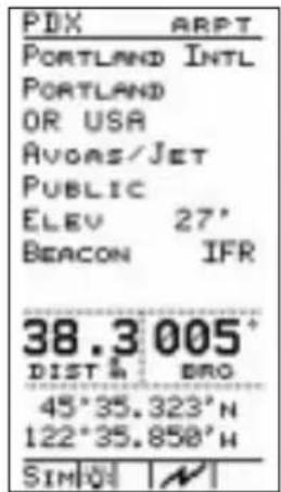
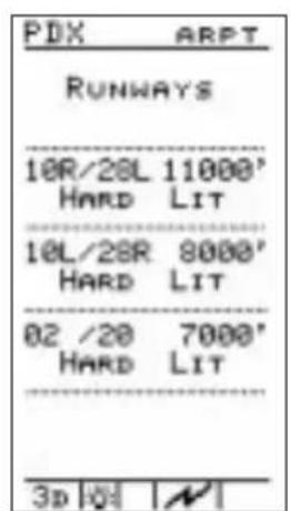
ARPT Waypoint Information 66
Tutorial....69
Starting the Simulator 70
Preparing for the Trip 71
Originating the Trip....71
Assigning a Direct Waypoint....71
Navigating the Trip 72
Looking Around. 72
Getting Waypoint Information 73
Checking Alert Settings....74
Approaching the Destination....75
Setting Up a Route....76
Starting a Route 78
Navigating a Route 79
Route "Direct To" 79
Track History....80
Navigating to a Nearest Waypoint....82
Conclusion. 83
Troubleshooting....84
Contacting the Factory....84
Glossary of Navigation Terms 87
Display Care and Cleaning....91
Battery Care....92
Charging the Battery 92
Battery Memory....92
Desktop Charger 92
History of Revisions
July 1995 Original Release
August 1995 Revision 01
April 1996
software)
February 1997
software)
Revision 02 (Version 5.0)
Revision 04 (Version 5/6.1
Ordering Information
To receive additional copies of this Precedus GPS User's Guide, order part #560-0110-04. The Precedus Quick Reference Guide is part #560-0115-01.
Important Notice
The Global Positioning System (GPS) is operated by the United States Department of Defense which is solely responsible for the accuracy, daily operation, and maintenance of the satellite constellation. System accuracy is affected by the Department of Defense's Selective Availability (SA) and the Dilution of Precision (DOP) attributed to poor satellite geometry.
This product is not intended for use as a sole source of navigation information. Exclusive reliance on this device in any navigation application is discouraged.
FCC Notice
This equipment has been tested and found to comply with the limits for a Class B digital device, pursuant to part 15 of the FCC Rules. These limits are designed to provide reasonable protection against harmful interference in a residential installation. Operation is subject to the following two conditions: (1) this device may not cause harmful interference, and (2) this device must accept any interference received, including interference that may cause undesired operation. This equipment generates, uses and can radiate radio frequency energy and, if not installed and used in accordance with the instructions, may cause harmful interference to radio communications. However, there is no guarantee that interference will not occur in a particular installation. If this equipment does cause harmful interference to radio or television reception, which can be determined by turning the equipment off and on, the user is encouraged to try to correct the interference by one or more of the following measures:
• Reorient or relocate the receiving antenna.
- Increase the separation between the equipment and receiver.
- Connect the equipment into an outlet on a circuit different from that to which the receiver is connected.
- Consult the dealer or an experienced radio/TV technician for help.
Changes or modifications to this equipment not expressly approved by II Morrow Inc. could void the user's authority to operate this equipment.
DOC Notice
This digital apparatus does not exceed the Class B limits for radio noise emissions from digital apparatus as set out in the radio interference regulations of the Canadian Department of Communications.
Aviation Applications
The Precedus handheld GPS receiver is intended for use as a navigation aid. In aviation applications, the receiver should be used to complement certified navigation instruments already installed in the aircraft. This device is not intended for use as a primary or sole source of navigation information in aviation applications. Never fly the aircraft without other available means of navigation. For maximum safety and to minimize distraction in the cockpit, place the receiver in an easily visible location, within convenient view of other avionics.
This device emits a small amount of electromagnetic energy. Do not place the receiver closer than 250 mm (approx. 10") to the wet compass in the cockpit.
Due to implementation of Selective Availability by the United States Department of Defense (DoD), all GPS receivers may suffer degradation of position accuracy. The DoD has stated that 95% of the time accuracy will not be degraded more than 100 m and 99.9% of the time accuracy will not be degraded more than 300 m.
The following guidance has been issued by the FAA, Seattle Aircraft Certification Office and Seattle Aircraft Evaluation Group on December 12, 1994. It is relevant to the use of portable GPS navigation systems in aircraft:
The information contained in FAA Flight Standards Notice No. 8310.171, dated October 19, 1992, is still applicable. The use of portable GPS receivers in aircraft falls under FAR 91.21 for Portable Electronic Devices for operations conducted under FAR part 91 Operating Rules Only. It is the responsibility of the aircraft operator to ensure that the device does not interfere with other systems in the aircraft. The GPS system must not be used for primary navigation and can only be used for comparison purposes during flight(s).
Introduction to GPS Navigation
GPS Overview
The Global Positioning System (GPS) is a constellation of 24 satellites in six orbit lanes 10,898 nautical miles above the earth at an inclination angle of about 55 degrees from the equator. Each satellite orbits the earth twice in 24 hours.
The GPS was developed and the satellites launched by the U.S. Department of Defense with the original intent of supplying highly accurate position fix information for military applications. In recent years, commercial applications for the information provided by this system have steadily increased in the civilian sector. Some of the more popular civilian uses of the system include surveying and position fix data recording for civil engineering applications, and a broad range of marine, aviation, and terrestrial navigation applications.
While orbiting the earth, each GPS satellite transmits complex streams of data containing the operational status and orbital location of all the satellites in the system. The Precedus™ receives this data stream and processes the information to determine which satellites are “visible” to the receiver’s antenna. With this determination made, the receiver chooses satellites to calculate a position fix. Using information transmitted from three or more satellites, the
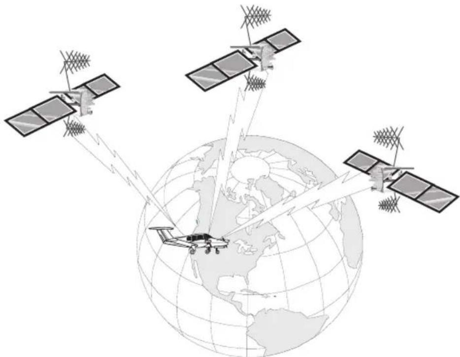
natural_image
Illustration of three satellites orbiting Earth with ground-based communication links (no text or symbols)GPS System Accuracy
unit can calculate latitude and longitude (usually abbreviated Lat/Lon); with four or more satellites, GPS altitude can also be calculated.
The GPS allows a high degree of position fix accuracy. The system can produce a position fix accurate to within less than one meter. Due to concern for national security, the U.S. Department of Defense introduces constant errors to the transmitted satellite data to degrade the accuracy of the system. Called Selective Availability, this practice limits GPS position fix accuracy to about 100 meters, although the relative position of the satellites to one another, their elevation above the horizon, and other factors can also affect accuracy of the position fix. Under optimal conditions, accuracy can improve to within 10 meters. GPS position fix accuracy is not affected by atmospheric conditions.
GPS altitude is based on a mathematical model of the sphere of the earth. Including intentional degradation, GPS altitude may differ from barometric altitude by several hundred feet.
Summary
Unlike navigation aids providing a position fix with data from land-based sources, the Precedus™ can provide an accurate position fix over land or sea anywhere in the world. The unit includes an extensive database of useful waypoint information and allows you to create up to 1,000 “customized” waypoints of your own. With the power of this navigation device in the cockpit, you can easily navigate with unsurpassed accuracy.
Operation Basics
This section introduces you to the Precedus and describes its controls and operating functions.
Controls
Menu/Pwr

This button turns the unit ON and OFF, and also allows you to select features from the Main Menu. Turn the unit ON by pressing the MENU PWR button once. Turn the power OFF by pressing the MENU PWR button and holding it down for two seconds. Press MENU PWR while viewing the Main Menu to adjust the display backlight.
Enter

Press the ENTER button to accept the selected or highlighted information.
Arrow keys The arrow buttons allow you to move the "cursor" to

highlight information that you want to select.
New Waypoint

Use the New Waypoint function to create your own waypoints and store them in the Precedus's memory. You can create and name up to 1,000 of your own waypoints. A Waypoint is a place you navigate from and to. A Waypoint can be based upon your present position, or you can enter latitude and longitude coordinates (abbreviated as Lat/Lon) to define the waypoint location.
Info

Use this function to get information about any waypoint in the Precedus's built-in database, including those you have created.
Available information includes:
• Waypoint identifier and type (Airport, VOR, NDB, Intersection, or User)
- Bearing and distance to the waypoint from your current position
• Lat/Lon coordinates of the waypoint
- For airports, the elevation, fuel availability and type, radio communication frequencies, runway details, and more
• Sunrise/Sunset calculator
GOTO and The GOTO and Nearest functions operate together. Press this Nearest button once for the GOTO function or twice for the Nearest

Waypoint function. Use the GOTO function to assign a destination waypoint from the Precedus's built-in database or one that you personally create. The Nearest function, always available when you use the GOTO function, provides a list of 30 waypoints of each type nearest to your present position. These two functions allow you to quickly and easily create a flight plan, or change it while navigating.


Display Information The display shows information for each operating function. Information typically includes navigation progress, waypoint information, satellite tracking status, menu options and selections.
Helpful Instructions on the The Precedus shows you what to do for most functions. Helpful instructions will appear in a "pop-up" box on the display and advises you on which button to press for options.
NavigationDisplaySample

Display Backlight & Contrast Display contrast and the display backlight are adjustable to best suit viewing conditions. See “Screen/Light” in the Function Reference Section for details on adjusting the screen. Choose the Screen/Light selection from the Main Menu. Press the ◀ or ▶ buttons to choose OFF, LO, MED, or HI intensity for the backlight. Press ▲ or ▽ to reach the Contrast setting. Press the ◀ or ▶ buttons to choose the desired contrast level. Press ENTER to save your choices and exit this function. You can also quickly change the backlight or display contrast from the Main Menu display. Press MENU PWR again to adjust the backlight. Press the ◀ ▶ buttons to adjust the display contrast.
Display Screens
Information you view on the display while using the Precedus shows one page or “screen” at a time. Many of the operating functions can show more than one screen of information. When more than one screen of information is available, either the vertical arrow symbol or an instruction line shows on the display to inform you that more information awaits your view. Follow the instruction, or if the vertical arrow symbol shows on the display, press or ▲ to view this additional information.
Information screens available while using each operating function are introduced here. The Function Reference section contains additional details about each operating function.
Startup Screen
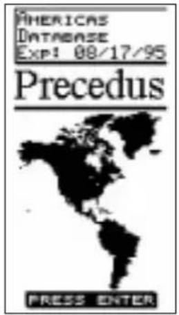
The startup screen shows on the display for several seconds after you switch on the Precedus. While this screen shows on the display, the unit performs internal diagnostics, begins tracking available GPS satellites, and activates the navigation function. The database type and expiration date is also shown during startup. Press ENTER , or wait a few seconds, and this screen will be replaced by navigation information.
This process takes only a few seconds, providing that a seed position and current time have been entered.

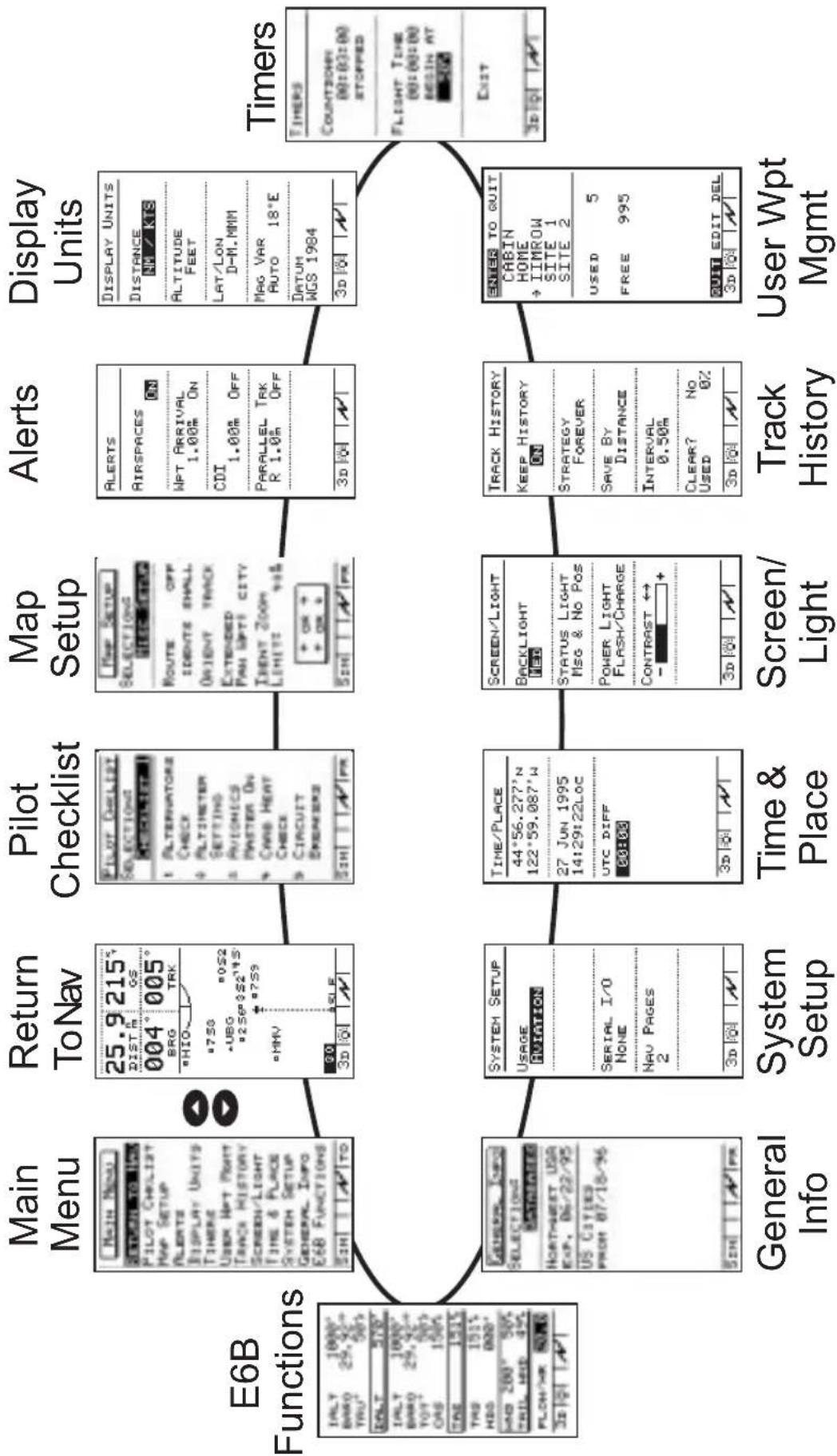
flowchart
graph TD
    A["Return to Nav\nNav Pages\nMessages\nGPS Status\nRoute\nMoving Map"] --> B["E6B Functions\nDensity Alt. & Winds Aloft\nFuel Plan"]
    C["Pilot Checklist\nStore and Edit up to four preflight checklists"] --> D["General Info\nSoftware Version\nDate/Time\nDatabase\nDB Memory\nGPS Version"]
    E["Map Setup\nAirports\nVORs\nNDBs\nINTs\nRoads\nCities\nBorders\nUSERS\nIdents\nRoute\nOrient\nAirspace"] --> F["System Setup\nUsage\nSerial I/O\nNav Pages"]
    G["Alerts\nAirspaces\nWPT Arrival\nCDI\nParallel Track"] --> H["Time & Place\nLat/Lon\ndate/Time\UTC"]
    I["Display Units\nDistance\nAltitude\nLat/Lon\Mag Var\Datum"] --> J["Screen/Light\nBacklight\nStatus Light\nPower Light\Contrast"]
    K["Timers\nCountdown\Flight Time"] --> L["User WPT Mgmt\nEdit\nDelete"]
    B --> L
    D --> L
    F --> L
    H --> L
    J --> L
    L --> M["User WPT Mgmt\nEdit\nDelete"]
    N["Return to Nav\nNav Pages\nMessages\nGPS Status\nRoute\nMoving Map"] --> O["Return to Nav\nNav Pages\nMessages\nGPS Status\nRoute\nMoving Map"]
    P["Pilot Checklist\nStore and Edit up to four preflight checklists"] --> Q["Pilot Checklist\nStore and Edit up to four preflight checklists"]
    R["Map Setup\nAirports\nVORs\nNDBs\nINTs\nRoads\nCities\nBorders\nUSERS\nIdents\nRoute\nOrient\nAirspace"] --> S["Map Setup\nAirports\nVORs\nNDBs\nINTs\nRoads\nCities\nBorders\nUSERS\nIdents\nRoute\nOrient\nAirspace"]
    T["Airspaces\nWPT Arrival\nCDI\nParallel Track"] --> U["Airspaces\nWPT Arrival\nCDI\nParallel Track"]
    V["Display Units\nDistance\nAltitude\nLat/Lon\Mag Var\Datum"] --> W["Display Units\nDistance\nAltitude\nLat/Lon\Mag Var\Datum"]
    X["Timers\nCountdown\Flight Time"] --> Y["Timers\nCountdown\Flight Time"]
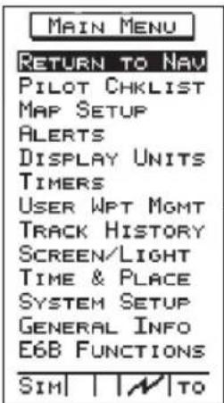
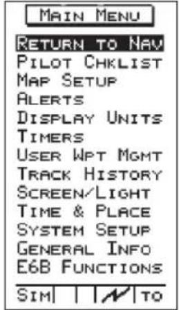
Main Menu
The Main Menu function contains options that control many ways the Precedus operates and lets you customize the navigation function to suit your preference.

Press the MENU button to display the main menu. Highlight the selection from the list by pressing the buttons. Press ENTER to go to the selected function.
The main menu contains these options:
- Return to Nav - Returns the unit from the menu to the navigation function.
- Pilot Chklist - Provides storage and viewing of up to four preflight checklists
- Map Setups - Contains control settings for information shown on moving map screens (navigation function) includes airspace type, distance buffer, and time buffer.
- Alerts - Controls alert messages for airspace entry, waypoint arrival, course deviation indication and alert message, and creates a parallel course that is offset by a selected distance from your chosen course.
- Display Units - Contains control settings for navigation units of measure, control settings for magnetic variation in course headings, and map datum.
- Timers - Controls built-in timers for countdown and flight time.
- User Wpt Mgmt - Controls editing or deletion of waypoints you have entered in the Precedus's memory.
- Track History - Controls navigation “track point” storage in memory and whether points show on moving map navigation screens (in the Navigation function).
• Screen/Light -
Control settings for display backlight and contrast, status light programming, and power light programming.
• Time and Place - Contains seed position and current time settings including UTC differential.
- System Setup -
Controls operation mode, power saver option, either of the two serial ports for interface with external devices, and the number of NAV pages shown.
- General Info - Enables showing of unit serial number, current hardware and software versions, and available databases.
• E6B Functions - Perform calculations of important information related to temperature, wind, and barometric pressure.
Using the menu function does not interrupt navigation. The Reference section describes how to use each main menu option.
Navigation Function
The Precedus has several screens available while you use the navigation function. Each screen contains useful information. You may also customize your screens. You can "scroll" or page through the other available screens by pressing the buttons
This function starts automatically when the unit is switched on and stays active. You will use this function most often while flying. The navigation function provides information about:
- Your current position and navigation progress to a destination
• GPS satellite signals
• Routes, or trips with multiple legs
• Events or conditions important to trip navigation
NAV Function Summary

flowchart
graph LR
    A["Nav Info & Moving Map"] --> B["Nav Info 1"]
    B --> C["Nav Info 2"]
    C --> D["Nav Info 3"]
    D --> E["Nav Info 4"]

    subgraph Moving Map
        F["05° 215° DIST"] --> G["004° 005° BRG TRK"]
        H["75° 0S2 UBO 256°0S2 14° 7.59"]
        I["30° SLE 3D"] --> J["Route 01 ON 01 SLE A 005°44.2° 02→PDX A 30°2°80.9° 02 OLM A 021°37.0° 07 SEA A"]
        K["28.6° 3D"] --> L["GPS Status 6 12172120242526"]
        M["28.6° 3D"] --> N["Messages 4000' 2300' 28005' DIST BRO ENTER FOR NEXT"]
        O["3D"] --> P["GPS Status 17 23 21 19 17"]
        Q["3D"] --> R["Messages 4000' 2300' 28005' DIST BRO ENTER FOR NEXT"]
        S["3D"] --> T["GPS Status 17 23 21 19 17"]
    end

    subgraph Route
        U["05° 44.2° 02→PDX A 30°2°80.9° 02 OLM A 021°37.0° 07 SEA A"]
        V["3D"] --> W["GPS Status 6 12172120242526"]
        X["3D"] --> Y["Messages 4000' 2300' 28005' DIST BRO ENTER FOR NEXT"]
        Z["3D"] --> AA["GPS Status 17 23 21 19 17"]
    end
    subgraph GPS Status
        AB["05° 44.2° 02→PDX A 30°2°80.9° 02 OLM A 021°37.0° 07 SEA A"]
        AC["3D"] --> AD["GPS Status 6 12172120242526"]
        AE["3D"] --> AF["Messages 4000' 2300' 28005' DIST BRO ENTER FOR NEXT"]
        AG["3D"] --> AH["GPS Status 17 23 21 19 17"]
    end
    subgraph Messages
        AI["05° 44.2° 02→PDX A 30°2°80.9° 02 OLM A 021°37.0° 07 SEA A"]
        AJ["3D"] --> AK["GPS Status 6 12172120242526"]
        AL["3D"] --> AM["Messages 4000' 2300' 28005' DIST BRO ENTER FOR NEXT"]
        AN["3D"] --> AO["GPS Status 17 23 21 19 17"]
    end
    subgraph HSI Display
        AP["540° 186' DIST"] --> AQ["540° 186' BRO"]
        AR["540° BRO"] --> AS["540° BRO"]
        AT["540° BRO"] --> AU["540° BRO"]
    end
Getting Started the First Time
This section explains how to get started using the Precedus. Information in this section explains how to startup the unit, check signals from the GPS satellites, enter a seed position, assign a destination waypoint, and detach your antenna.
This section shows you how to start the Precedus and check for proper operation. It is necessary to enter a seed position and the current time the first time you turn the unit on.
• Charge the battery before using the Precedus
- Power on
• Enter a seed position (your dealer may have already completed this step for you)
• Enter the current time
• Check satellite signal strength
• Enter a "GOTO" waypoint
- Begin navigating
Power Up

To switch the unit on, press MENU . The startup screen and database information shows on the display for several seconds and then will go into the Navigation function.
Seed Position
The first time the Precedus is switched on, it must locate satellites in the sky to acquire signals before determining a position fix in a complex process involving lengthy mathematical operations. Without a seed position and the current time and date, this process can take 10 minutes or more to complete. Enter a Seed Position to allow the receiver to quickly locate and track available satellites.
Note

The seed position and current time only needs to be entered the first time the receiver is switched on.
This information is stored in memory and need not be entered again. If you move about three hundred miles without the Precedus turned on and tracking its position, reenter the seed position.
Entering a Seed Position
![TIME/PLACE 04°07.396'N 123°13.121'H 12 JUN 1995 14:01:28LOC UTC DIFF 00:00 3D [S] [A]](/content/2026/06/1199560/images/0c9759b40223d9517035e2a51a0934203985a717bfba75151b3c99fcbf73af5e.jpg)
- Press MENU to reach the main menu. Press the ▲ button highlight the “Time & Place” function. Press ENTER to go to the “Time and Place” function.
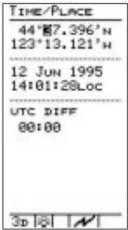
- Set the latitude and longitude coordinates near to your current position. Use the bottoms of change values. The bottoms have the highlight on the screen to select the next value to change.

- Set the current date. Use the buttons to change values. The buttons move the highlight on the screen to select the next value to change.

- Set local time. (Or enter UTC time and skip step 5 below.) Use the arrow buttons to select and set local time (LOC). Press tENTORve the information.
You may also enter current UTC time and skip entry of UTC differential in step 5. It is not necessary to enter seconds - they cannot be set.

- Set the difference between local time and UTC time. Press ENTER to save the information.
Use the illustration on the next page to determine the UTC differential for your area. Enter this value as the difference between local and UTC time (UTC DIFF).
As an example, the UTC DIFF value in Seattle, Washington would be +08:00 (or +07:00 during daylight savings time).
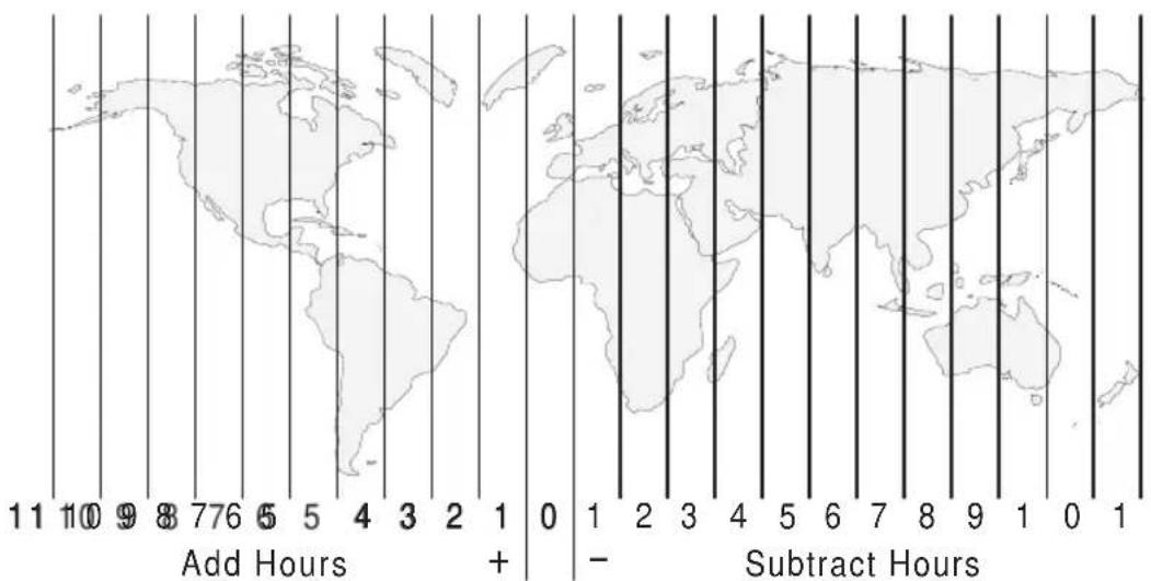
Subtract 1 hour during summer for Daylight Savings Time (where DST applies)
- Press ENTER once again. The values you set are now entered into memory and the main menu will be displayed.
The unit shows the GPS signal strength screen in the Navigation function.
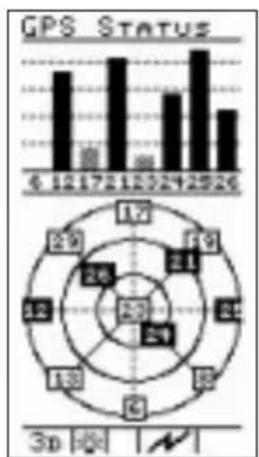
Checking GPS Signal Strength
While the Precedus acquires signal information from satellites, the bars representing signal strength show grey in color. This process takes place quickly. When the unit has acquired a signal and begins tracking a satellite, the bar will change to black.
The GPS signal strength screen is located in the Navigation function. Make it a habit to check this screen to make sure that the unit is properly tracking visible satellites before you fly.
bar
GPS STATUS | Period | Value | |---|---| | 6 | 12 | | 12 | 17 | | 17 | 21 | | 21 | 25 | | 25 | 29 | | 30 | 33 | | 35 | 38 | | 40 | 43 | | 45 | 48 | | 50 | 53 | | 55 | 58 | | 60 | 63 | The image contains two charts: the top is a bar chart showing GPS status over time, and the bottom is a circle chart displaying GPS status over time. The numbers inside the circles represent the corresponding GPS values at each time point. The '3p' label indicates the time period in seconds.In this example, the GPS Status screen shows that eight satellites are available, seven satellites are being tracked, and five signals (dark boxes) are acquired and usable for navigation. The Precedus requires signals from at least four satellites to calculate a 3D position fix (Lat/Lon and GPS altitude).
Checking Each Satellite Press the ◀ ➤ buttons to view information about the visible satellites.
Important!
The GPS antenna must be able to “see” each satellite it is tracking. If a satellite is “shaded” by the wing or fuselage during a turn, it may temporarily lose track of that satellite. If this happens, or if the geometry of the satellites available is poor, the unit may temporarily calculate a “2D Fix” and altitude information will not be available.

Entering a Destination Waypoint With a seed position and the current time and date set, the Precedus is ready to begin navigating a trip. Prepare for trip navigation by entering a destination waypoint.
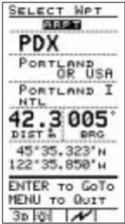
1. Press the button.
The GOTO Nearest Waypoint function screen is displayed with the distance and bearing from your present position to the indicated waypoint.
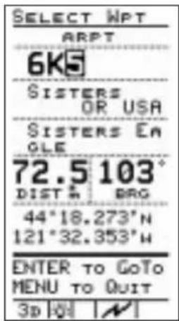
2. Select a destination waypoint. Use the
buttons to change the highlighted character in the waypoint identifier. The buttons move the highlight on the screen to select the next character to change.
Note
Waypoints are stored in the unit's built-in database. By moving the highlight with the
buttons to ARPT and pressing the buttons, you can change the type of destination waypoint to select: airport, NDB, VOR, INT, or USER (user created). For instance, with ARPT indicated as the type of destination waypoint, only airports show on the display as you select identifier characters.

Hint
For airport waypoints, press the 🏠 🏠 buttons to move the highlight on the screen down to the second line containing the city name. You can select characters in this line, too. The icons roll through waypoint names that most closely match the characters you select.


- You can also scroll through each waypoint in the database. With the highlight over the first character of either the waypoint identifier OR city name, press the 🔍 button once. A highlighted vertical arrow symbol will appear to the left of the first character.
Use the b.w ns to scroll through each waypoint in the Precedus's built-in database.

- Make sure correct waypoint is selected. Press the ENTER button to enter your information.
The selected waypoint is now set as the destination. The display shows the navigation screen in use before the GOTO function was started in step 1.
External Antenna The built-in regular antenna for the Precedus may be removed and used as an external antenna. A dummy antenna is inserted into the Precedus to replace the built-in antenna. A six-foot cable is provided to connect to the regular antenna.
-
Detach the built-in antenna by sliding it to the right and pulling it away from the Precedus.
-
Replace the built-in antenna with the dummy antenna, the one with the cable attached to it.
-
Attach the dummy antenna by inserting the tab at the base of the antenna into the notch above the display. Then, push the top of the antenna down into the cavity and slide the antenna to the left as you align the antenna connectors.
-
Hold the antenna bracket in front of you with the open part of the suction cup facing up. Insert the tab at the base of the regular antenna into the lip of the bracket, align the connector with the opening in the bracket, and then press the antenna firmly into place.
-
Insert the gold-plated connector at the end of the cable into the gold-plated connector on the regular antenna.
-
Apply the suction cup and antenna bracket to the windshield.

flowchart
graph TD
    A["Suction Cup"] --> B["Antenna Bracket"]
    B --> C["External Antenna Cable"]
    B --> D["Antenna Connectors"]
    D --> E["Regular Built-In Antenna"]
    D --> F["Dummy Antenna"]
    D --> G["Antenna Connectors"]
Navigation Basics
This section explores the navigation function and describes the powerful features it contains. When you become comfortable operating the unit, you may wish to “fly” the Precedus using the built-in simulator. Follow the instructions in the Tutorial section.
About the Navigation Function
The navigation function is always active. When you use other functions, the navigation function continues to run “in the background” calculating your present position, navigating your programmed route (if active), and alerting you to events or conditions important to navigation. When you finish using other functions and return to the navigation function, the last navigation screen used is displayed.
About the Navigation Function Screens
While you navigate, the Precedus gives you information in the Navigation function screens. Screens provided are: zero to four Navigation information screens (number is selected by the user in the System Setup function), HSI Display, messages, GPS status, route waypoints, navigation information and moving map, and moving map alone. The navigation information screens are user-programmable.
The ▼ ▲ buttons “scroll” or page forward or backward through the screens. This section describes each screen.
NAV Function Summary

flowchart
graph TD
    A["Nav Info & Moving Map"] --> B["Nav Info 1"]
    B --> C["Nav Info 2"]
    C --> D["Nav Info 3"]
    D --> E["Nav Info 4"]
    E --> F["HSI Display"]

    subgraph_Map_1["Map Icon: 25.9, 215°, 004°, 005°, 8ND, THX, +750, -205°, +250°, +88°, +2°, +725°, +3D, +1"]
    end

    subgraph_Map_2["Map Icon: 570°, 151°, 2992°, TAS, BARO, +15°, +242°, HXD SP, HXD DIS, +8.6°, +000°, TL HXD, HDX, +4.0, +4.0, +4.0, +4.0, +4.0, +4.0, +4.0, +4.0, +4.0, +4.0, +4.0, +4.0"]
    end

    subgraph_Map_3["Map Icon: 40.7°, 160°, 00-15°, 14-38°, 12-32°, 14-22°, 12-27°, 12-22°, 12-18°, 12-14°, 12-10°, 12-8°, 12-6°, 12-5°, 12-4°, 12-3°, 12-2°, 12-1°"]
    end

    subgraph_Map_4["Map Icon: 37.5°, 160°, 0°, -0°, -0°, -0°, -0°, -0°, -0°, -0°, -0°, -0°, -0°, -0°, -0°, -0°, -0°, -0°, -0°, -0°"]
    end

    subgraph_Map_5["Map Icon: 35.1°, 160°, 005°, 005°, 00-13°, 14-36°, 87°, -3D, +1"]
    end

    subgraph_Map_6["Map Icon: 29.9°, 30.6°, -750°, -750°, -750°, -750°, -750°, -750°, -750°, -750°, -750°"]
    end

    subgraph_Map_7["Map Icon: Route: GPS Status: Messages: HSI Display"]
    end

    subgraph_Map_8["Map Icon: Route: GPS Status: Messages: HSI Display"]
    end

    subgraph_Map_9["Map Icon: GPS Status: Messages: HSI Display"]
    end

    subgraph_Map_10["Map Icon: GPS Status: Messages: HSI Display"]
    end

    subgraph_Map_11["Map Icon: GPS Status: Messages: HSI Display"]
    end

    subgraph_Map_12["Map Icon: GPS Status: Messages: HSI Display"]
    end

    subgraph_Map_13["Map Icon: GPS Status: Messages: HSI Display"]
    end

    subgraph_Map_14["Map Icon: GPS Status: Messages: HSI Display"]
    end

    subgraph_Map_15["Map Icon: GPS Status: Messages: HSI Display"]
    end

    subgraph_Map_16["Map Icon: GPS Status: Messages: HSI Display"]
    end

    subgraph_Map_17["Map Icon: GPS Status: Messages: HSI Display"]
    end

    subgraph_Map_18["Map Icon: GPS Status: Messages: HSI Display"]
    end

    subgraph_Map_19["Map Icon: GPS Status: Messages: HSI Display"]
    end

    subgraph_Map_20["Map Icon: GPS Status: Messages: HSI Display"]
    end

    subgraph_Map_21["Map Icon: GPS Status: Messages: HSI Display"]
    end

    subgraph_Map_22["Map Icon: GPS Status: Messages: HSI Display"]
    end

    subgraph_Map_23["Map Icon: GPS Status: Messages: HSI Display"]
    end

    subgraph_Map_24["Map Icon: GPS Status: Messages: HSI Display"]
    end

    subgraph_Map_25["Map Icon: GPS Status: Messages: HSI Display"]
    end

    subgraph_Map_26["Map Icon: GPS Status: Messages: HSI Display"]
    end

    subgraph_Map_27["Map Icon: GPS Status: Messages: HSI Display"]
    end

    subgraph_Map_28["Map Icon: GPS Status: Messages: HSI Display"]
    end

    subgraph_Map_29["Map Icon: GPS Status: Messages: HSI Display"]
    end

    subgraph_Map_30["Map Icon: GPS Status: Messages: HSI Display"]
    end

    subgraph_Map_31["Map Icon: GPS Status: Messages: HSI Display"]
    end

    subgraph_Map_32["Map Icon: GPS Status: Messages: HSI Display"]
    end

    subgraph_Map_33["Map Icon: GPS Status: Messages: HSI Display"]
    end

    subgraph_Map_34["Map Icon: GPS Status: Messages: HSI Display"]
    end

    subgraph_Map_35["Map Icon: GPS Status: Messages: HSI Display"]
    end

    subgraph_Map_36["Map Icon: GPS Status: Messages: HSI Display"]
    end

    subgraph_Map_37["Map Icon: GPS Status: Messages: HSI Display"]
    end

    subgraph_Map_38["Map Icon: GPS Status: Messages: HSI Display"]
    end

    subgraph_Map_39["Map Icon: GPS Status: Messages: HSI Display"]
    end

    subgraph_Map_40["Map Icon: GPS Status: Messages: HSI Display"]
    end

    subgraph_Map_41["Map Icon: GPS Status: Messages: HSI Display"]
    end

    subgraph_Map_42["Map Icon: GPS Status: Messages: HSI Display"]
    end

    subgraph_Map_43["Map Icon: GPS Status: Messages: HSI Display"]
    end

    subgraph_Map_44["Map Icon: GPS Status: Messages: HSI Display"]
    end

    subgraph_Map_45["Map Icon: GPS Status: Messages: HSI Display"]
    end

    subgraph_Map_46["Map Icon: GPS Status: Messages: HSI Display"]
    end

    subgraph_Map_47["Map Icon: GPS Status: Messages: HSI Display"]
    end

    subgraph_Map_48["Map Icon: GPS Status: Messages: HSI Display"]
    end

    subgraph_Map_49["Map Icon: GPS Status: Messages: HSI Display"]
    end

    subgraph_Map_50["Map Icon: GPS Status: Messages: HSI Display"]
    end

    subgraph_Map_51["Map Icon: GPS Status: Messages: HSI Display"]
    end
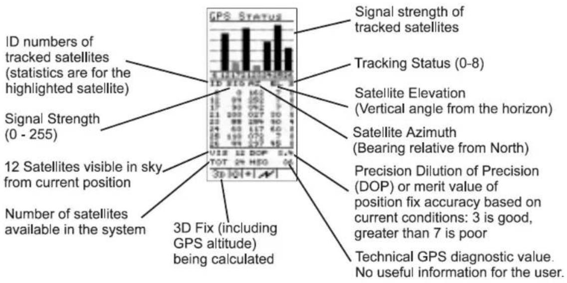
GPS Status
The GPS Status screen contains information about signals received from visible satellites in the sky.
The GPS information screen tells you:
- The type of position fix currently calculated by the unit: 0D: no signals available
2D: the position fix is calculated based on signals from only three satellites and GPS altitude is not available
3D: the position fix is calculated based on signals from four or more satellites, and GPS altitude is available
• The total number of operational GPS satellites in orbit
- The number of satellites visible in the sky from your position and their status
- The Dilution of Precision (DOP) value for the position fix provided by the satellite constellation - a high value (6 or greater) indicates poor position reliability, while a value of 3 or less indicates good position reliability
In addition, individual satellite information is available by pressing the location follows:
• The strength of the received signal from each satellite
- The satellite azimuth and elevation from the current position
- The GPS receiver's current track status for each visible satellite
Messages The Precedus helps you navigate by informing you of important events or conditions while you fly. When an important event or condition occurs, an alert message shows on the display to inform you. When you see one of these alerts on the display, follow the instruction shown to clear it. Clearing the alert removes it from the display. The screen shown before the alert appeared returns to the display. Alerts may show on the display anytime the unit is operating.
Custom You can customize the Navigation Information pages by Navigation selecting the information shown in each of the windows.
Screens
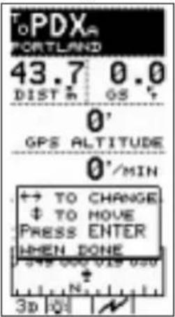
- In the Navigation function, press and hold the ENTER button to highlight the top information window.

- Press the w on to move the highlight to the desired window.
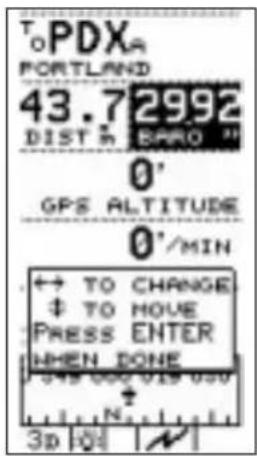
-
Press the ◀ ➕ buttons to choose the desired navigation information. There are thirty-four different navigation information choices available.
-
Press ENTER to save this choice, or press the buttons to select another window to change.
A listing of the available navigation screens is given on the next page.
Navigation Information Choices
| 35.8DIST# | 1. Distance to Current Destination WPT | 00:30:09ETK | 18. Estimated Time Enroute |
| 41.2RTE # | 2. Distance to Route Destination WPT | 00:30:55ROUTE ETE | 19. Route Estimated Time Enroute |
| 200*GE | 3. Ground Speed | 15:15:23ETA | 20. Estimated Time of Arrival |
| 005*BRD | 4. Bearing | 15:22:20ROUTE ETA | 21. Route Estimated Time of Arrival |
| 005*TRK | 5. Track Angle | 15:20:21FLIGHT TIME | 22. Flight Time |
| 005*DTK | 6. Desired Track | 00:00:01COUNTDOWN | 23. Countdown Timer |
| 44.2XTK # | 7. Cross Track Error | 00:00:01UTC | 24. Universal Time Coordinate |
| E18*MAG | 8. Magnetic Variation | 25. Graphic Course Deviation Indicator | |
| 1014BARO H | 9. Barometric Pressure (E6B) | 0GPS ALTITUDE | 26. GPS Altitude |
| 50*TRU* | 10. True Air Temperature (E6B) | 0°/HEN VENT. SPEED | 27. Vertical Speed |
| 50*TOT* | 11. Total Air Temperature (E6B) | 47°32.128"N121°22.355"N | 28. Present Position Lat/Lon |
| 200*CAS | 12. Calculated Air Speed (E6B) | TOPDXAPORTLAND | 29. Destination Waypoint |
| 200*TAS | 13. True Air Speed (E6B) | 0°IND ALTITUDE | 30. Indicated Altitude |
| 185*HDG | 14. Heading (E6B) | 0°DIEN ALTITUDE | 31. Density Altitude (E6B) |
| 185*HND DIR | 15. Wind Direction (E6B) | FUEL 000 019 ONLATE/National | 32. Graphic Compass Bearing |
| 20*HND SP | 16. Wind Speed (E6B) | FUEL 3.9TO MFT PEK | 33. Fuel To Waypoint |
| 20*HD HND | 17. Head Wind (E6B) or Tail Wind (E6B) | FUEL 4.1TO ROUTE END | 34. Fuel To Route End |
| 49*TL HND | 35. Blank |
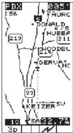
Moving Map Screen
The following information shows in highlighted boxes at each corner of the display:
• The destination waypoint
• Bearing to the destination waypoint
- Map scale
• Range to the destination waypoint
The moving map screens represent graphic views of your navigation progress. Your present position is indicated by the airplane symbol near the center of the display. Note that the display orientation may be changed so that the top of the may be North, Desired Track, or Track. The Map Setup option, described in the Function Reference section, explains how to change the orientation.
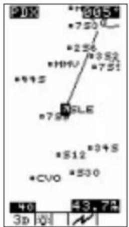
You can change the scale by pressing the location the scale may be changed from 0.1 nm to 250 nm or set to auto for each waypoint type. In this case, the distance from the airplane icon to the top of the screen is 40 miles.

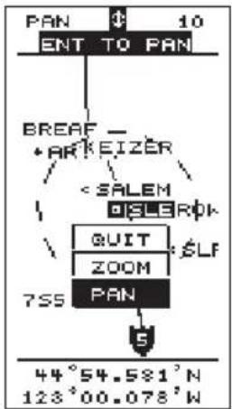
Panning the Press the ENTER button while viewing the moving map. The Moving Map screen displays "PAN" in the upper left corner and the "airplane" changes to a crosshair. Press the ENTER button ENTER again to display Pan and Zoom options. Press the or ▲ buttons to select "Quit," "Zoom," or "Pan." With
flowchart
graph TD
    A["PAN"] --> B["ENT TO PAN"]
    B --> C["BREAF - ARKEIZER"]
    C --> D["<SALEM"]
    D --> E["QUIT"]
    E --> F["ZOOM"]
    F --> G["7S5"]
    G --> H["PAN"]
    H --> I["44°54.581'N\n123°00.078'W"]
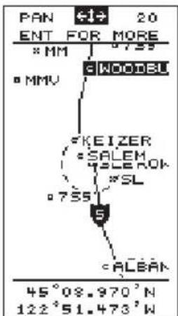
“Pan” selected, press ENTER to start the Pan feature. Move the crosshair with the arrow keys.
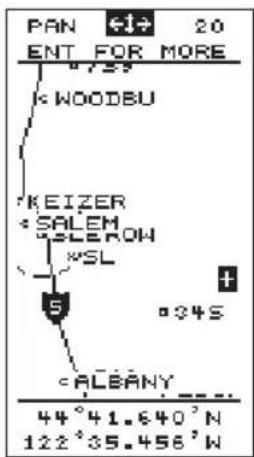
When the crosshair touches the edge of the map, the map will redraw to continue panning in the desired direction.
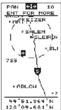
GOTO a Waypoint in Pan Mode
Move the cross hair with the arrow keys. When the crosshair touches the symbol that marks a waypoint and the waypoint name is reversed, press INFO to view information about the waypoint. Press to set the highlighted waypoint as the destination waypoint. Then press ENTER
Creating a Waypoint in Pan Mode
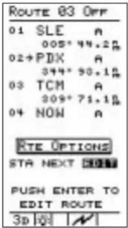
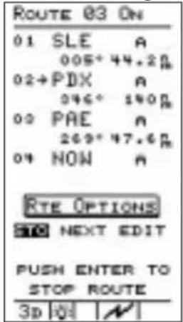
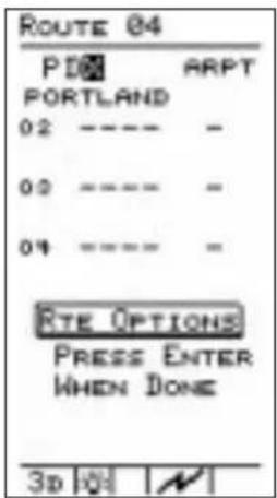
The Route Screen The Precedus can store up to 20 reversible trip plans or “routes” in memory. Each route can consist of up to 30 waypoints using either those you create or those from the built-in waypoint database.
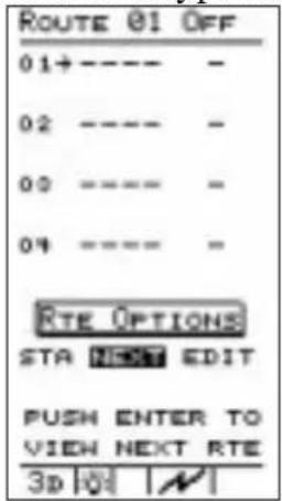
The route screen shows the status (ON or OFF) and up to four waypoints of each route, as well as the desired track and distance between consecutive waypoints. Only one route may be active, or ON, at any time while you navigate. When the route screen is displayed, review each route by pressing
ENTER when NEXT is highlighted. The procedure to set up routes is explained later in this section.
Searching for Nearest Waypoints An important feature of the Precedus is its ability to locate waypoints closest to your position as you fly. Should you have to land the aircraft quickly, you can use this feature to locate a nearby waypoint, assign it as a destination, and quickly navigate to it.
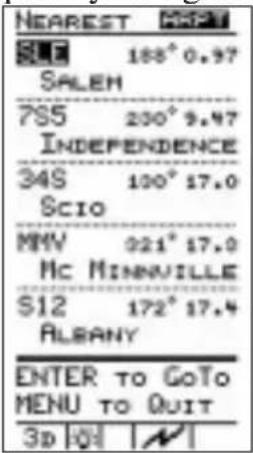
While navigating, press the button twice to activate the nearest function and search for waypoints closest to your present position.
The nearest function screen shows up to 30 nearest waypoints in order of distance from your present position. The waypoint type, bearing to the waypoint, and range to the waypoint also shows.
Press the ▼ button to move the arrow cursor down the list to select a destination. Press INFO to view waypoint information. Press GO TO NRST and then the ENTER button to assign your chosen waypoint as a destination. The display returns to the navigation function automatically.
You can also return to the navigation function without assigning a new destination waypoint from the list by pressing the button.
Important

You can control the types of waypoints that show on the display as the result of a search for nearest waypoints. The “MAP SETUP” menu function allows you to choose whether or not to display airports, VORs, NDBs, and intersections as searched waypoints and on the moving map screens. Before you fly, make sure to check this option and confirm that the waypoint types you wish to show will appear on the display after a search and while using the moving map screens.
Creating User Waypoints
The Precedus allows you to create up to 1,000 of your own waypoints, each with a 6-character name you choose. As you navigate, you may wish to create waypoints at locations that are important to you, or waypoints to which you plan to return. You can use your present position or enter either lat/lon coordinates or radial and distance position relative to another waypoint for the waypoint's location.
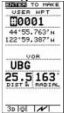
Use the new waypoint function to create waypoints. Press the button and the current position coordinates are assigned to the next user waypoint number. The new waypoint function screen allows you to enter a waypoint name of your choice, or you can use the default waypoint name that the unit assigns as a number.

Press the button to move the highlight to the desired character in the waypoint name. Press the buttons to change it. Once you have entered the desired waypoint name, you can assign it to the new waypoint in place of the automatically assigned number by pressing the ENTERN.
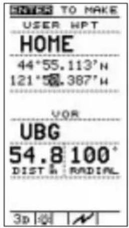
If you want a different location for your new waypoint, use the <1> <2> buttons to move the highlight and the
buttons to change the waypoint Lat/Lon or radial and distance coordinates. When you are finished, press ENTER to enter the new waypoint into memory.
You can also create new waypoints in the Pan mode as detailed on page 24.
You can always edit or delete waypoints you have created. The menu function “User Waypoint Management” function allows you to perform these tasks. The use of this option is described in the Function Reference section.
Getting Waypoint Information
Use the information (INFO) function anytime to get information on waypoints in the Precedus's memory, including waypoints you have created. A listing of available information is included in the Waypoint Database section.
Destination Waypoint Information
Press the INFO button to activate the waypoint information function. The waypoint information screen shows on the display with information about the current destination waypoint. Press the △ ▽ buttons to scroll through additional screens of information about the waypoint. Press a INFO to return to the Navigation function.


Information You can also get information about any other waypoint in About Other memory by using the GOTO function together with the Waypoints waypoint information function.

Press the GO TO NRST button as if you were assigning a destination waypoint. Use the button to select the waypoint name. When the desired waypoint name shows on the display, press the INFO button to get information about the waypoint.
Press the INFO button again to return to the previous page.
Information About Nearest Waypoints
The waypoint information function also works with the nearest function. This allows you to quickly get information about any of the waypoints nearest to your present position.

Press the GO TO NRST button twice to search for nearest waypoints. When the list of these waypoints shows on the display, press the button to move the arrow cursor down to the desired waypoint. Press the INFO button to get information about the waypoint.
Scanning Waypoints for Information

Press a 980 to return to the previous display.
You can “scan” waypoints on the moving map screens to get information quickly. With a moving map screen showing on the display, press several times.
Notice that the highlight moves from the destination waypoint to a different waypoint on the screen each time you press this button. When the highlight has moved to the desired waypoint, press the button to information about that waypoint.
Navigating Multiple Flight Plans The ability of the Precedus to store multiple leg flight plans is very useful. Once you set up a route, you can navigate the plan in forward or reverse. You can also edit a route you have created, or select any waypoint from a route and navigate directly to it, skipping other waypoints and legs of the trip. You can select waypoints by type, identifier, or name.
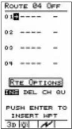
Creating a Route
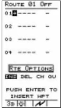
Select “EDIT” from the route screen to begin creating route number 01. Then select “INSERT” to insert waypoints into the route.
Prepare to insert waypoints into your route beginning with the waypoint of origin. Then you can insert other waypoints in the order you will travel to them, working toward the destination waypoint.

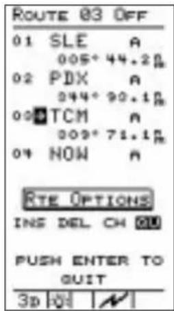
Use the button▼ 1 ▶ select and change the waypoint identifier and type for the first waypoint. When the desired waypoint shows on the first line of the display, press ENTER The arrow cursor moves to the second line for insertion of waypoint number 02. Repeat the process you used to insert the first waypoint into the route.

As you add waypoints, the route screen shows the bearing and distance between each waypoint.
While editing a route, move the cursor to any waypoint and press INFO to view information about that waypoint. Press INFO again to return to route editing.

When you finish inserting waypoints into the route, select "DONE" with the
buttons and press the ENTER button then in the same way select "QUIT" to complete route editing.
Remember, you can always change, add, or delete route waypoints later.

When you finish with the first route, you can immediately create another. The screen shows route 02, empty and ready for insertion of waypoints. To create a new route, select “EDIT” and proceed as with creation of route 01.
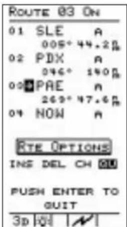
Changing a Route Waypoint

You can change any waypoint along a route. Select the route to change from the route screen. If you have several routes created, press the ENTER on while "NEXT" is highlighted to page through the routes. When the correct route shows on the display, select "EDIT" as if creating a route.

Press the △ ▽ buttons to select a waypoint to change. When the cursor arrow points to the desired waypoint, select “CHANGE” to change it.
Change the waypoint as desired. Repeat for other waypoints to change.
Each time a change is made, "DONE" is highlighted. When waypoints are changed as desired, press ENTER complete route editing.
Adding a Route Waypoint. You can add waypoints to any route. Add waypoints to a route by inserting them into the route at the proper location.
vwaypoint
Select the route from the route screen that you want to insert waypoints. Then, select "EDIT" as if creating a route.
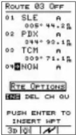
Press the button to move the cursor arrow to the waypoint where you wish to insert the new waypoint.
Select "INSERT" with the <1> buttons and press ENTER to insert a waypoint into the route.

Select a waypoint with the arrow buttons. When desired waypoints are inserted into the route, press ENTER for "DONE," select "QUIT," and press ENTER again to complete route editing.
Deleting Route Waypoints To delete waypoints from a route, scroll through the route screen pages to select the route that you wish to delete waypoints. Then, select "EDIT" as if creating a route.
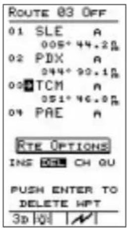
Use the button to move the marker arrow to the waypoint you wish to delete. Select "DELETE" to delete the waypoint from the route and press the button.

When desired waypoints are deleted from the route, select "QUIT" with the <1> buttons and press ENTER complete route editing.
Note

Deleting waypoints from routes will not remove them from the waypoint database.
Starting a Route When you are ready to navigate a route, it must be started. Only one route can be started, or active at any time.
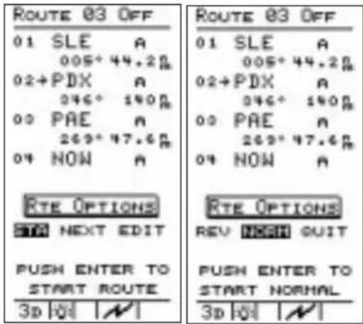
Select the route you wish to start from the route menu. Use the <▶▶> buttons to select "START" and press ENTER . Select "NORMAL" with the <▶▶> buttons and press ENTER start the route.
Only one route can be “started” or active at any time. You can navigate the route in either direction, depending on your present position. If your present position is at the last waypoint in the route, you could use this last waypoint as the point of origin by selecting “REVERSE.”
After a route is started (route “ON”), you can view other routes or edit them. From any route screen, you can quickly return to the active route by pressing the ◀ ➤ buttons to select “NEXT” and then pressing the ENTER button. With “NEXT” highlighted press ENTER to page through the routes that you have stored.
Fixed Map To use a fixed point as the center reference on the display, first select the desired reference point. You can select any point on or off the current display using any of the available methods. With the waypoint selected press INFO and then press twice to bring up the Info Map. The selected point will remain centered on the map and the plane icon will move in relation to that point. Press INFO again to return to NAV.
Stopping or While flying a route, you may wish to deviate from your Holding a intended flight plan. You may later resume travel on this route. You can “HOLD” the route to do this. A route on “HOLD” can be resumed later from the current leg. The route is still active, but leg sequencing is stopped while you deviate from the planned course of travel.
You may wish to abandon an active route to navigate a different route or to travel to waypoints not in the route. Press the GO TO NRST button, select a new waypoint, and press ENTER. If the new waypoint is not in the active route, the route will be stopped. If you wish just to stop the route, use the "STOP" option.
Stop or hold the active route by selecting "STOP" or "HOLD" from the route menu with the bottom and then press. ENTER
You can also select "QUIT" to avoid any action and return to the active route screen.
Resuming a Route

Select "START," press ENTER then select "RESUME" with the buttons and press ENTER to resume a route on hold.

Route "Direct To" While navigating a route, you may wish to bypass one or more waypoints and proceed directly to a destination waypoint. The route "Direct To" feature allows you to do this.
Select the active route from the route menu. Then, select "EDIT" with the < > buttons and press ENTER
Press the button to move the marker arrow to the waypoint you want to navigate to. Then, press the GO TO NRST button. The waypoint information screen will be displayed. Press ENTER to enter the waypoint as the destination.
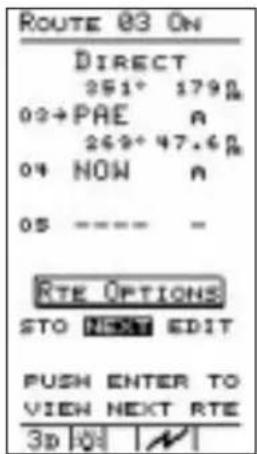
The route screen shows "Direct" status to the waypoint.
You can now navigate directly to the desired destination waypoint, bypassing previous waypoints in the route.
Creating an The Precedus allows you to setup an approach route using Approach the established approach waypoints. Route
- Select "EDIT" from the Route Options with the ON and press ENTER . Then, select "INS" and press ENTER .
- Use the arrow buttons to select the desired airport designator and then press ENTER .
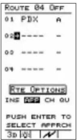
- For the next waypoint on the route, select "APP" from the Route Options with the location of the user ENTER .
Note
The cursor must be below the desired airport and at the last entry for your flight plan. Inserting an approach automatically removes the airport identifier and inserts the approach waypoints.


- Select the desired approach waypoint group with the location and then press ENTER to insert the approach route.
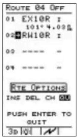
- Select "QUIT" with the buttons and press ENTER . The approach route is now set. The route will show the bearing and distance between each waypoint.
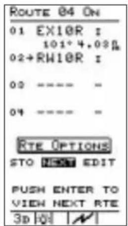
- When you are ready to navigate your approach route, select "START" with the button and press. Select "NORMAL" and press activate your route.
Note
The Approach Monitor feature is for pilot information only. Your Precedus may not be used as the primary navigation device for an IFR approach.

Function Reference
This section provides detailed information on the functions you can select from the Main Menu. The Main Menu gives you access to functions that modify the operation of your Precedus and the way navigation information is displayed. The menu options allow you to customize the to best suit your navigation requirements. A list of menu option default settings (those in effect when the unit is first switched on) for each option is included at the back of this section. Option settings are stored in memory and remain in effect until you change the settings again.
Note

Navigation is not interrupted while you use the other functions.
The menu function makes these options available:
- Return to Nav - (Page 40) Returns the unit from the menu to the navigation function.
- Pilot Checklist - (Page 42) Provides storage, editing, and display of up to four preflight checklists.
- Map Setups - (Page 45) Contains control settings for information shown on moving map screens (navigation function), airspaces, road data, and city and user waypoints.
- Alerts - (Page 49) Controls alert messages for airspace entry, waypoint arrival, course deviation indication and alert message, and creates a parallel course that is offset by a selected distance from your chosen course.
- Display Units - (Page 50) Contains control settings for navigation units of measure, control settings for magnetic variation in course headings, and map datum.
- Timers - (Page 54) Controls built-in timers for countdown and flight time.
- User Wpt Mgmt - (Page 55) Controls editing or deletion of waypoints you have entered in the Precedus's memory.
- Track History - (Page 55) Controls navigation “track point” storage in memory and whether points show on moving map navigation screens (Navigation function).
• Screen/Light - (Page 57)
Control settings for display backlight and contrast, status light programming, and power light programming.
• Time and Place - (Page 58)
Contains seed position and current time settings including UTC differential.
• System Setup - (Page 58)
Controls operation mode, either of the two serial ports for interface with external devices, and the number of NAV pages shown.
• General Info - (Page 61)
Enables showing of unit serial number, current hardware and software versions, and current databases.
• E6B Functions - (Page 62)
Perform calculations of important information related to temperature, wind, and barometric pressure.
The Main Menu
The main menu displays the functions available.
Press the MENU button. When the main menu shows on the display, select the desired option by pressing the buttons to move the arrow cursor up or down the list of functions. With the desired option selected, press the ENTER button to activate it.
Changing Menu Option Settings
Changing settings on any menu option screen is done in the same way. Use the ▼ ▲ buttons to move the highlight on the screen to the option item you wish to change. Then use the ◀ ▶ buttons to change the setting.
Return to Nav
Use this option to leave the menu function and return to the Navigation screen last viewed.
Note

"RETURN TO NAV" is automatically selected when you press MENU PWR. If you accidentally select the wrong menu option or if you decide to abandon making changes, press the MENU button again to return to the main menu.
Main Menu Function Summary
flowchart
graph TD
    A["E6B Functions"] --> B["Main Menu"]
    B --> C["Return ToNav"]
    C --> D["Pilot Checklist"]
    D --> E["Map Setup"]
    E --> F["Alerts"]
    F --> G["Display Units"]
    G --> H["Timers"]

    subgraph E6B Functions
        I1["General Info"]
        I2["System Setup"]
        I3["Time & Place"]
        I4["Screen/Light"]
        I5["Track History"]
        I6["User Wpt Mgmt"]
    end

    I1 --> J["SYSTEM Setup"]
    I2 --> J
    I3 --> J
    I4 --> J
    I5 --> J
    I6 --> J
    J --> K["Return ToNav"]
    K --> L["Pilot Checklist"]
    L --> M["Map Setup"]
    M --> N["Alerts"]
    N --> O["Display Units"]

    style A fill:#f9f,stroke:#333
    style H fill:#ccf,stroke:#333
Pilot Checklist
The preflight checkout is one of the most important parts of your flight. To help with your workload and increase your safety, the Precedus includes a menu item to store up to four Pilot Checklists. There is a predefined list of items that you can select for viewing on each checklist.
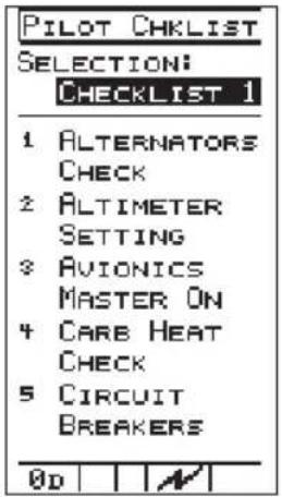
Highlight "PILOT CHECKLIST" in the Main Menu and press ENTER. Use the ◀ or LEDs to select the desired Checklist (1 to 4).
Press the buttons move through the Checklist and highlight individual items.
Creating a New Checklist
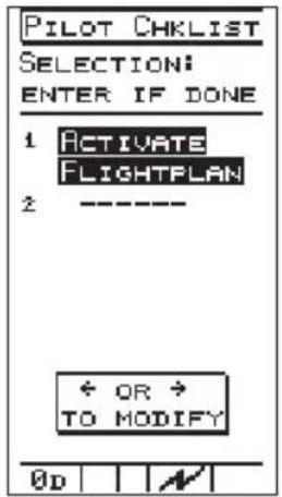
While viewing the desired Checklist, press the button to move the highlight to the first item on the Checklist. With "INS" (insert) highlighted, press . ENTERct the desired item with the < buttons and press . ENTER

Now, for the next item. With "INS" highlighted, press . ENTER ct the desired item with the o < < > buttons and press . ENTER
Continue until you are finished selecting items and then use the o◀▶ buttons to highlight “QU” (Quit) and press . ENTER
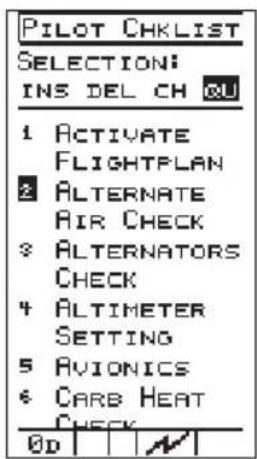
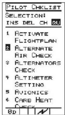
Edit an Existing Checklist
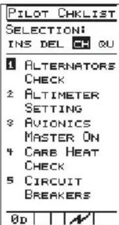
While viewing the desired Checklist, press the buttons to move the highlight to the item on the checklist.
With the o"ottons"ove the highlight to "INS," "DEL" (Delete), or "CH" (Change) and press .ENTER
If you selected "INS" or "CH", select the desired item with the ▲ ▼ buttons and press ENTER. Continue until you are finished selecting items and then press the ◀ button highlight "QU" and press ENTER
Pilot Checklist Options The following list shows the options available for you to select from for the Pilot Checklist function
- Activate Flightplan
- Alternate Air Check
- Alternators Check
- Alternators On
- Alternators Off
- Altimeter Setting
- Avionics
- Avionics Master On
- Avionics Master Off
- Carb Heat Check
- Canopy Closed
- Circuit Breakers
- Compass
- Compass System Free
- Compass System Slave
- Contact Approach
- Contact Clearance Delivery
- Contact Departure
- Contact Ground
- Contact Tower
- Cowl Flaps Close
- Cowl Flaps Open
- Cowl Flaps Set
- DG Setting
- Doors
- Engine Prime
- Flaps Down
- Flaps Up
- Flaps Set
- Fuel Pumps Check
- Fuel Pumps Off
-
Fuel Pumps On
-
Fuel Quantity
- Fuel Selectors Set
- Gear Up
- Gear Down
- Generators Check
- Generators On
- Generators Off
- HSI Course
- HSI Heading
- Instruments Check
- Landing Lights
- Mag Check
- Mags Off
- Mags On
- Master Switch Off
- Master Switch On
- Mixture Set
- Navigation Lights
52 Navigation Set - Oil Pressure
- Passenger Briefing
- Props Pitch Setting
- Radios Set
- Rotating Beacon
- Seat Belts
- Seats Locked
- Speed Brake Set
- Strobe Lights
- Takeoff Trim
- Trim Set
-
Windows Closed
-
Nav Systems (VOR) Check
Map SetupsThis option controls the type of waypoints that show on the moving map screens, the size of the text, whether or not a Route Path or Airspaces are shown, and the orientation of the moving map. The pages available in Map Setup include Misc Setup, Aviation Wpts, Airspaces, Road Data, City Wpts, and User Wpts.
Misc Setup
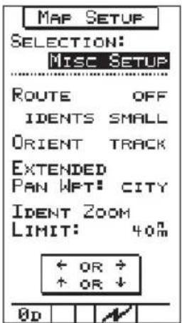
Highlight "MAP SETUP" in the Main
Menu and press ENTER the buttons to select the desired Map Setup page. If you do not have a particular database loaded, the setup page for that database with not be shown.
In MiscSetup, press the △ ▼ buttons to highlight “Route Off/On.” Press the ◀ or ▶ button to select “On” or “Off.” With Route turned On, a line representing your intended flight path shows on the moving map screens to aid you in navigating to your destination.
Press to highlight "Route Idents." Press of a selected off, Small, Medium, or Large. This sets the size that text will appear on the map displays.
Press to highlight "Orient." Press or to elect "Track, DTK (Desired Track), or North" for the top of the screen on the moving maps.
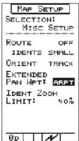
In MiscSetup, press the △ ▽ buttons to highlight “Extended Pan Wpt.” Press the ◀ or ▶ button to select the type of waypoint that will be displayed in Pan mode when the Zoom scale displays an area outside of the currently viewable waypoints. Waypoint types available are: None, Int, Arpt, VOR, NDB, and City. Normally, the nearest 30 waypoints of each type are shown.
Aviation Waypoints
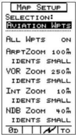
Press highlight "Ident Zoom
Limit." Press out selected
distance from your position that waypoint identifiers will be displayed. Set the units (nm, mi, or km) in the DISPLAY UNITS menu item in the Main Menu.
Press to highlight "All Wpts."
Press out select "N" or
“OFF.” With this option you choose to display Aviation waypoints on the moving maps.
Press ▼ to highlight the waypoint type Zoom distance. Waypoint types are Airport, VOR, Intersection, and NDB.
Press of select Zoom
distance; that is distance from your position that waypoints will be displayed. Selections are from OFF to 250 nm.
Airspaces

Press to highlight the "Idents"
size. Press on o elec
"Off, Small, Medium, or Large" for each waypoint type. Press t ENTER save the selected choices
In Map Setup, select "Airspaces." Press
to highlight Class B, C, or D
Airspaces. Press
Sector, Outer, or Off for each selection.
Grouping is slightly different in the International Database.
Press ▼ to highlight "Spec Use." Press or to select ON or OFF.
Press to highlight the Distance
Buffer value. Press o

select the value.
The distance buffer is the distance from the airspace border where you will be alerted. This distance can be shown in
the unit of measure you choose using the "DISPLAY UNITS" setting described later in this section.
Press ▼ to highlight the Time Buffer value. Press ⬆ select ▶ the value.
The Time Buffer contains the travel time (based upon current track and speed) from the airspace border where you will be alerted.
ATC Ring

Press ENTER to save the selected choices When ATC Ring is set to ON, a ring five nautical miles in radius is drawn around any airport that has a control tower frequency.
No alerts are provided for nearing the ATC ring; it is only a visual marker on the map screens for your convenience
User Wpts

Press ▼ to highlight the desired item. Press ⬆ select b desired choice.
Press ENTER to save the selected choices.
Road Data

The Road database allows you to show interstate, U.S., and state highways on the map pages of your Precedus.
All Roads - Choose ON or OFF.
Choose ON to display roads and road names on the map pages. Choose OFF to not display road information.
Zoom - Choose the distance from your position that a particular road type will be shown. If you choose OFF, that particular road type will not be shown on the map pages.
Idents - Choose ON or OFF. Choose ON to display the road identifiers for the selected Road type. Choose OFF to no display the identifier; the road will still be drawn.
Press to highlight the desired item. Press of a selective desired choice.
City Wpts

Press ENTER to save the selected choices.
The City database in Map Setup allows you to show the location and name of cities on the map pages of your Precedus.
All Cities - Choose ON or OFF. Choose ON to display the cities and city names on the map pages. Choose OFF to not display city information. City location is shown as a “+” on the map.
City Zoom - Choose the population threshold for the cities that will be shown. If you choose OFF, cities will not be shown on the map pages.
Idents - Choose OFF, SMALL, MEDIUM or LARGE. Choose OFF to
not show the city name; a “+” will still show the location. SMALL, MEDIUM and LARGE determine type size for the city name.
Press ▼ to highlight the desired item. Press ⬆ select the desired choice.
Press ENTER to save the selected choices.
Alerts This option controls whether or not and when the Precedus should alert you if you approach special use airspace or arrival at a destination. You can also set up your CDI resolution or Parallel Track distance, as well as alerts for these features.

Highlight "ALERTS" in the Main Menu and press the buttons to select AIRSPACES. Press
or to select "ON" or "OFF." When Airspaces are "ON," an alert message will appear in the Navigation function when you enter a special use airspace.
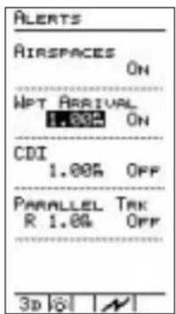
Press your highest the number value for WPT ARRIVAL. Press or to select the radius distance around the destination waypoint where the Precedus alerts you. This distance can be shown in the unit of measure you choose using the "DISPLAY UNITS" setting described later in this section. Press to highlight the ON/OFF option. Press or to select "YES" or "NO." If you choose "YES" for the alert message, the arrival alert will show on the display to advise you of arrival at your destination waypoint.
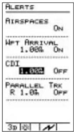
Press ▼ highlight the number value for CDI. Press ◀ or ▶ to select the distance off your course where the Precedus alerts you. The number you select is the distance from the center to the left or right side of the CDI scale in the NAV function. Press ▼ to highlight the ON/OFF option. Press ◀ or ▶ to select “YES” or “NO.” If you choose “YES” for the alert message, the course deviation alert will show on the display advising you when course deviation exceeds the CDI scale maximum value left or right.

Press do to highlight the direction for Parallel Track. Press or ▶ to select L/R (Left or Right of your current course). Now press to highlight the distance. Press◀ or ▶ to select the distance value. This function allows you to set a course to a destination that is parallel to your original course and offset by a distance you select. The Precedus alerts you when you exceed this distance.
Display Units
This option controls the way navigation units of measure show on the display. The units of measure you select show consistently throughout all screens in all operating functions. You also can set the Magnetic Variation and Map Datum.
Units of measure for each navigation parameter:
• Distance - nm/kts (nautical miles/knots); sm/mph (statute miles/miles per hour); km/kph (kilometers/kilometers per hour)
• Altitude-feet; meters
- Lat/Lon - d-m.mmm; d-m-s.s (where d=degrees, m=minutes, s=seconds of latitude or longitude), and UTM
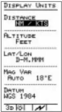
In the Main Menu press, o to highlight "DISPLAY UNITS" and press . enters or to select the Distance unit type.
Press the ▼ button to highlight the Altitude value and then press◀ or ▶ to select the desired type.
Press the w on to highlight Lat/Lon and then press d to select the desired type.


Press the ▼ button to highlight Mag Var and then press ◀ ▶ select Automatic, Manual, or True North. If you selected Manual, press the ▼ button to highlight the degrees value. Press set the degrees and direction value.
To disable magnetic variation, select "TRUE." All course headings will be referenced to true north.
Note
The Precedus automatically sets magnetic variation to 0 degrees when you fly above 70 degrees north or south latitude. It is not necessary to disable automatic magnetic variation as you travel north or south to high latitude regions.

Press the ▼ button to highlight the Map Datum Type and then press ◀ or ▶ to select the desired Map Datum.
The following list shows the GPS map datums contained within the Precedus. Each map datum represents a mathematical model of the earth used for the purpose of establishing precision in charting various areas of the earth. Since each datum relies on a different mathematical model, inconsistencies exist in defining the location of charted points between datums. For this reason, it is important to verify that you have selected the correct map datum for the area where you navigate and the chart you use.

Note
WGS-1984 is the default datum until you change it.
| Datum Name Ellipsoid | Ellipsoid (Model) |
| ARC 1950 Clarke 1880 | |
| ARC 1960 Clarke 1880 | |
| Australian Geodetic 1966 Australian National | |
| Australian Geodetic 1984 Australian National | |
| Bogota Observatory International | |
| Campo Inchauspe International | |
| Cape Clarke 1880 | |
| Carthage Clarke 1880 | |
| Chatham 1971 International | |
| Chua Astro International | |
| Corrego-Allegre International | |
| European 1950 West Europe International | |
| European 1950 Cyprus International | |
| European 1950 Egypt International | |
| European 1950 Iran | International |
Datum Name Ellipsoid Ellipsoid (Model)
| European 1950 Sicily International | |
| European 1979 International | |
| Gandajika Base International | |
| Geodetic Datum 1949 International | |
| Hjorsey 1955 International | |
| Indian (Thailand/Vietnam) Everest | |
| Indian (Bangladesh/India/Nepal) Everest | |
| Ireland 1965 Airy Modified | |
| Kertau 1948 Everest Modified | |
| Liberia 1964 Clarke 1880 | |
| Luzon Clarke 1866 | |
| Massawa Bessel 1841 | |
| Merchich Clarke 1880 | |
| Minna Clarke 1880 | |
| Nahrwan Clarke 1880 | |
| North American 1927 Conus | Clarke 1866 |
| North American 1927 Alaska | Clarke 1866 |
| North American 1927 Canada | Clarke 1866 |
| North American 1927 Cntrl. Amer. | Clarke 1866 |
| North American 1963 GRS-80 | |
| Old Egyptian | Helmert 1906 |
| Old Hawaiian | Clarke 1866 |
| Oman Clarke 1880 | |
| Ordered Survey Great Britain 1936 | Airy |
| Pitcairn Astro 1967 | International |
| Quatar National | International |
| Qurmoq | International |
| Schwarzeck | Bessel 1841 |
| South America 1969 | S. America 1969 |
| Timbalai | Everest |
| Tokyo Bessel 1841 | |
| Zanderij | International |
| WGS-1972 | WGS-72 |
| WGS-1984 | WGS-84 |
Timers The Precedus includes timers for countdown and flight time. Use this option to count elapsed time for as long as 60 minutes. The timers can run “in the background” while you navigate and will not interfere with unit operation.
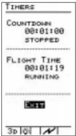
In the Main Menu, press ▼ or ▲ to highlight "TIMERS" and press ENTER

Press to highlight the Countdown time value. Press to select the desired time. Press to highlight "START?" and press to begin countdown from the total time shown.
As the countdown progresses, the screen shows "RUNNING." During the time you can stop the countdown, but will reset to the starting value when restarted. An alert message shows on the display when the countdown time has expired.
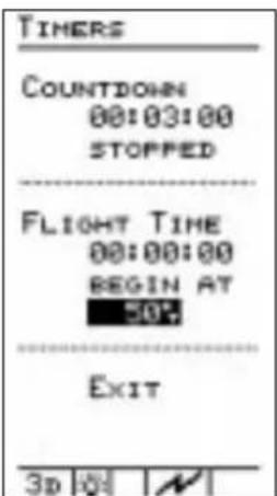
Press out high- and "BEGIN AT" for the Flight Time timer. Use the 10-point to select NOW, NEVER, POWER UP, or a speed between 5 and 200 kt as the starting point for the Flight Time counter. For instance, you may want to select a speed at which you are actually preparing for take-off to start your Flight Time counter.
User Waypoint Management
This option allows you to edit or delete waypoints you have created (user waypoints).
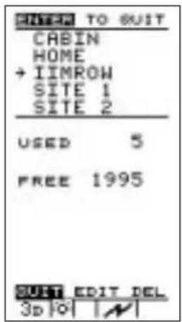
To edit a waypoint, press the buttons to highlight the desire waypoint. Press the button to select "EDIT" and then press
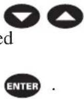
Move the highlight to the desired character with the 🔊 on ▶ Change the values with the ▽ buttons. When you finish making changes, press 📋 have the changes in memory.


To delete waypoints you no longer need, move the arrow cursor with the ▼ △ buttons to the waypoint you wish to delete. Move the highlight at the bottom of the screen with the ◀ ▶ buttons to “DEL” and press ENTER. The waypoint is removed from memory.
When you are finished, select "QUIT" with the 📁 or 🖼d press ENTER to return to the main menu.
Track History
The Track History function allows you to store a record of navigation progress in memory. The stored record consists of a series of track points, each containing your position at the time the point was stored. You can choose whether or not to store track points, how often to store them, and manage the storage process. You can store up to 2,000 track points.

In the Main Menu press, to highlight "TRACK HISTORY" and press ENTERESS or to highlight the ON/OFF setting for "KEEP HISTORY." Press to choose ON or OFF.
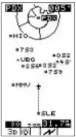
When track history is “ON,” points are stored in memory. Your track history displays on the moving map screens as a series of dots showing your flight path. Each dot indicates a stored point. When track history is “OFF,” no track points are stored or shown on the moving map screens.
Now press to reach "KEEP HISTORY." Press out choose the storage strategy. Select “FOREVER” to continuously store points, starting again and writing over existing points when memory becomes full, or select “UNTIL FULL” to stop storing points when memory becomes full.

![TRACK HISTORY KEEP HISTORY ON STRATEGY FOREVER SAVE BY DISTANCE INTERVAL 0.58% CLEAR? No USED 1/2 3D [OK] [N]](/content/2026/06/1199560/images/589f1762f0e821f2cea446ad0eef98acc7b1c13f01cb601e53d2c934cd3b3b3a.jpg)
Now press to reach "SAVE BY." Press out choose the method. Each storage method has the appropriate interval for the track points. Saving by "DISTANCE" allows you to select a distance interval. Saving points by "TIME" allows you to select the minutes and seconds interval for each track point.
“USED” shows you the percentage of memory space used for track point storage. If you wish to empty the memory of track points, select “CLEAR?” and choose “YES.”
Press ENTER when you have completed your choices.
Screen/ Light This function controls the backlight, Status Light, Power Light, and display contrast.

- In the Screen/Light function, press the <▶▶> buttons to select a Backlight intensity level of OFF, LOW, MED, or HIGH. A light bulb icon will appear at the bottom of the display when the backlight is turned on.
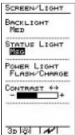
- Press to reach the STATUS LIGHT selection. The selected choice gives the conditions when the status light on the front of the Precedus will light. Press the light point choose your status light options.
• OFF - Status light will stay off
• MSG - Status light will turn on when a message is active
• NO POS - Status light will turn on when the GPS signal is lost
- MSG & NO POS - Status light will turn on when either a message is active or the GPS signal is lost
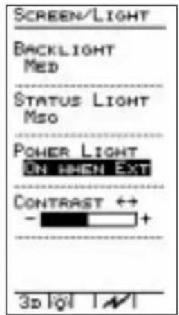
Press to reach the POWER LIGHT selection. Press the < > buttons to select OFF, ON WHEN EXT, or FLASH/CHARGE.
• OFF - Power light will stay off
- On When Ext - Power light will turn on when external power is supplied
- Flash/Charge - Power light will flash when the battery is charging
![SCREEN/LIGHT BACKLIGHT MED STATUS LIGHT MSG POWER LIGHT FLASH/CHARGE CONTRAST 0.0 - + - 3p [O] | N](/content/2026/06/1199560/images/5e90a663fc27015324eb50887bbaf648361d7dc4d900780782a71427863a0c76.jpg)
Press to reach the "CONTRAST" selection. Adjust the display contrast by pressing the bottom as you make adjustments, the horizontal bar shows the current contrast level. " - " indicates lower contrast, while "+" indicates higher contrast. The contrast setting you select is stored in memory and remains in effect until you change it.
Time and Place
Use this function to enter your present position and set UTC and local times. It is necessary to enter the time and place the first time the Precedus is switched on; this is called the "Seed Position." Time and place information you enter is stored in memory and need not be entered again. However, it is necessary to enter this information again if the unit is switched off and moved a distance of several hundred miles

In the Main Menu press, to highlight "TIME & PLACE" and press ENTER. The Lat/Lon position will be highlighted. Press the buttons to highlight each character to change and press the buttons to select the desired value. Repeat this operation for all necessary values.
System Setup
This function sets the Precedus operation mode (USAGE), Serial I/O, and the number of NAV Information pages available in the NAV function.
There are six operating modes (USAGE) available in the Precedus.
- Aviation
- Hiking
- Land Mobile
- Marine
- Survey
- Simulator
Each mode is optimized for the given activity. Generally you will use either the “AVIATION” or “SIMULATOR”
operation mode. Select “SIMULATOR” only when you wish to use the built-in simulator to practice navigating with the unit.
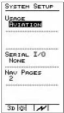
In the Main Menu press, to highlight "SYSTEM SETUP" and press .INTENS the buttons to select the desired USAGE.
If you choose the simulator mode, you can select the ground speed you “fly” the Precedus. All operating functions are available while you use the simulator. After simulator use, the unit returns automatically to the “AVIATION” operation mode the next time you switch on the power.
The Precedus is equipped with a serial data port for communication with external serial devices. This option controls the function of each port. Your choices include:
- None
• NMEA 183-1.5
• NMEA 183-2.0 - Moving Map
• DGPS 1200B
Using this option with appropriate electrical connections, you can:
- Connect the Precedus to your personal computer to manage waypoints you create*
- Send serial data to an external moving map display

- Send serial data matching the NMEA formats to any serial device in the cockpit capable of accepting it
- Disable the serial data port *See your II Morrow dealer or contact the factory for information about the optional Precedus/PC Interface Kit. Consult kit documentation for instructions on proper serial port settings.
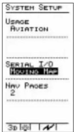
Press to highlight the "SERIAL I/O" function. Press the <1> buttons to select your choice.
The Precedus allows you to customize not only the content of the Navigation function pages, but also the number of information pages. These pages are the displays of navigation information, such as ground speed, altitude, CDI, distance to a waypoint, etc. The default value is two pages. You may select from zero to four pages. If you choose RESET, two pages will be selected and any modifications to your NAV Information pages will be removed.

Press to highlight the "NAV PAGES" function. Press the buttons to select your choice.
Press written you have completed your System Setup choices.
NAV Function Summary
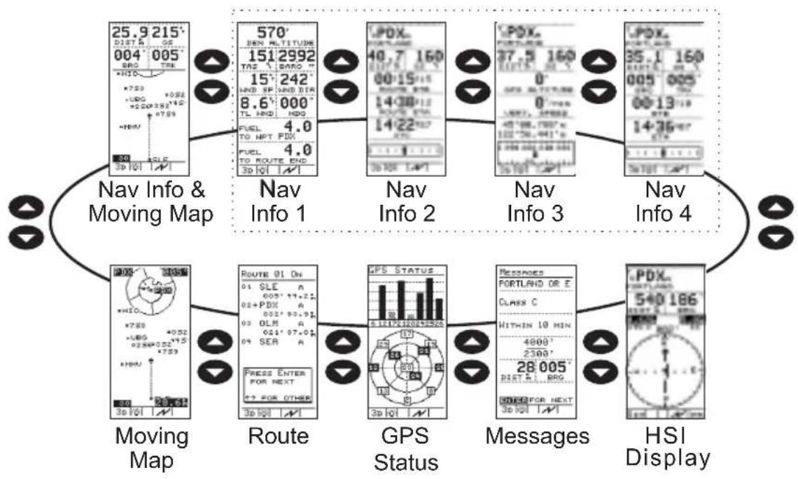
flowchart
graph TD
    A["Nav Info & Moving Map"] --> B["Nav Info 1"]
    B --> C["Nav Info 2"]
    C --> D["Nav Info 3"]
    D --> E["Nav Info 4"]
    E --> F["HSI Display"]

    subgraph_Map_1["Map Icon: 25.9, 215°, 004°, 005°, 006°, 007°, 008°, 009°, 010°, 011°, 012°, 013°, 014°, 015°, 016°, 017°, 018°, 019°, 020°"]
    end

    subgraph_Map_2["Map Icon: 570°, 151°, 2992°, 15°, 242°, 8.6°, 000°, TL HND, HDG, FUEL TO HPT PDX, FUEL TO ROUTE END, 3D I/OI"]
    end

    subgraph_Map_3["Map Icon: LPDX, 40.7, 160°, 00:15, 14:38, 112°, ROUTE STD, 14:22, 187°, 3D I/OI LAPT"]
    end

    subgraph_Map_4["Map Icon: LPDX, 37.5, 160°, 0°, 0°, 0°, 0°, 0°, 0°, 0°, 0°, 0°, 0°"]
    end

    subgraph_Map_5["Map Icon: LPDX, 35.1, 160°, 005°, 005°, 006°, 007°, 008°, 009°, 010°, 011°, 012°, 013°, 014°, 015°"]
    end

    subgraph_Map_6["Map Icon: LPDX, 35.1, 160°, 005°, 005°, 006°, 007°, 008°, 009°, 010°, 011°, 012°"]
    end

    subgraph_Map_7["Map Icon: LPDX, 35.1, 160°, 005°, 005°, 006°, 007°, 008°, 009°, 010°"]
    end

    subgraph_Map_8["Map Icon: LPDX, 35.1, 160°, 005°, 005°, 006°, 007°, 008°, 009°"]
    end

    subgraph_Map_9["Map Icon: LPDX, 35.1, 160°, 005°, 005°, 006°, 007°, 008°"]
    end

    subgraph_Map_10["Map Icon: LPDX, 35.1, 160°, 005°, 005°"]
    end

    subgraph_Map_11["Map Icon: LPDX, 35.1, 160°, 005°, 005°"]
    end

    subgraph_Map_12["Map Icon: LPDX, 35.1, 160°"]
    end

    subgraph_Map_13["Map Icon: LPDX, 35.1, 160°"]
    end

    subgraph_Map_14["Map Icon: LPDX, 35.1, 160°"]
    end

    subgraph_Map_15["Map Icon: LPDX, 35.1, 160°"]
    end

    subgraph_Map_16["Map Icon: LPDX, 35.1, 160°"]
    end

    subgraph_Map_17["Map Icon: LPDX, 35.1, 160°"]
    end

    subgraph_Map_18["Map Icon: LPDX, 35.1, 160°"]
    end

    subgraph_Map_19["Map Icon: LPDX, 35.1, 160°"]
    end

    subgraph_Map_20["Map Icon: LPDX, 35.1, 160°"]
    end

    subgraph_Map_21["Map Icon: LPDX, 35.1, 160°"]
    end

    subgraph_Map_22["Map Icon: LPDX, 35.1, 160°"]
    end

    subgraph_Map_23["Map Icon: LPDX, 35.1, 160°"]
    end

    subgraph_Map_24["Map Icon: LPDX, 35.1, 160°"]
    end

    subgraph_Map_25["Map Icon: LPDX, 35.1, 160°"]
    end

    subgraph_Map_26["Map Icon: LPDX, 35.1, 160°"]
    end

    subgraph_Map_27["Map Icon: LPDX, 35.1, 160°"]
    end

    subgraph_Map_28["Map Icon: LPDX, 35.1, 160°"]
    end

    subgraph_Map_29["Map Icon: LPDX, 35.1, 160°"]
    end

    subgraph_Map_30["Map Icon: LPDX, 35.1, 160°"]
    end

    subgraph_Map_31["Map Icon: LPDX, 35.1, 160°"]
    end

    subgraph_Map_32["Map Icon: LPDX, 35.1, 160°"]
    end

    subgraph_Map_33["Map Icon: LPDX, 35.1, 160°"]
    end

    subgraph_Map_34["Map Icon: LPDX, 35.1, 160°"]
    end

    subgraph_Map_35["Map Icon: LPDX, 35.1, 160°"]
    end

    subgraph_Map_36["Map Icon: LPDX, 35.1, 160°"]
    end

    subgraph_Map_37["Map Icon: LPDX, 35.1, 160°"]
    end

    subgraph_Map_38["Map Icon: LPDX, 35.1, 160°"]
    end

    subgraph_Map_39["Map Icon: LPDX, 35.1, 160°"]
    end

    subgraph_Map_40["Map Icon: LPDX, 35.1, 160°"]
    end

    subgraph_Map_41["Map Icon: LPDX, 35.1, 160°"]
    end

    subgraph_Map_42["Map Icon: LPDX, 35.1, 160°"]
    end

    subgraph_Map_43["Map Icon: LPDX, 35.1, 160°"]
    end

    subgraph_Map_44["Map Icon: LPDX, 35.1, 160°"]
    end

    subgraph_Map_45["Map Icon: LPDX, 35.1, 160°"]
    end

    subgraph_Map_46["Map Icon: LPDX, 35.1, 160°"]
    end

    subgraph_Map_47["Map Icon: LPDX, 35.1, 160°"]
    end

    subgraph_Map_48["Map Icon: LPDX, 35.1, 160°"]
    end

    subgraph_Map_49["Map Icon: LPDX, 35.1, 160°"]
    end

    subgraph_Map_50["Map Icon: LPDX, 35.1, 160°"]
    end
General Info
The General Info function tells you about the Databases that you have stored in the Precedus and other system information. In General Info, press ◀ or ▶ to access the available pages.
Databases

The Databases page shows the databases currently available in your Precedus and their date. You may have up to four databases loaded into your Precedus at a given time.
System Info
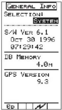
The System Info page shows your Precedus software version and date, database type, amount of memory in the database, and the GPS version. This information is for reference only and should be used whenever you contact a factory service representative. You cannot change any information on this page.
E6B Functions
Perform calculations of important information related to wind, temperature, and barometric pressure. The calculated results will be shown both on the E6B function page and in the Navigation pages. The E6B Calculator uses your actual ground speed, track, and magnetic variation for its calculations.
Density Altitude
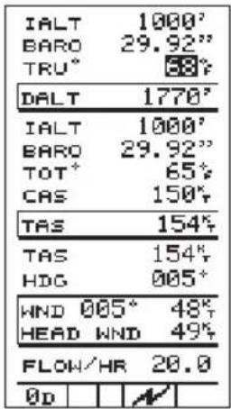
Highlight Indicated Altitude value (IALT) using , range in value using or Use the altitude indicated on your aircraft instruments. Change the units (feet or meters) in the DISPLAY UNITS menu.
Highlight the Barometer (BARO) value using , change the value using o highlight the symbol to the right of the value and use ◀ to select either inches (“) or millibars (mb).
Highlight the True Temperature (TRU) value using a single value using o. Press to highlight the measurement unit and press o. selected either Fahrenheit (F) or Celsius (C). The DALT value will update as you change values.
True Air Speed
| IALT | 1000' |
| BARO | 29.92" |
| TRU° | 68° |
| DALT | 1770° |
| IALT | 1000' |
| BARO | 29.92" |
| TOT° | 69° |
| CAS | 150° |
| TAS | 154° |
| TAS | 154° |
| HDG | 005° |
| HND 005° | 49° |
| HEAD WND | 49° |
| FLOW/HR | 20.0 |
| 0D |
Highlight Indicated Altitude value
(IALT) using, winge in value using or Use th
altitude indicated on your aircraft instruments. Change the units (feet or meters) in the DISPLAY UNITS menu.
Highlight the Barometer (BARO) value
using , using the value using or Highlight the
symbol to the right of the value and use
◀ ▶ to select either inches (“) or millibars (mb).
Highlight the Total Outside Temperature
(TOT) value using , change the value using o
Typically, the TOT and TRU values
will be the same until your speed
exceeds 250 kts. Press ▼ to highlight the measurement unit and press
or ⬆ sele ⬆ either Fahrenheit (F) or Celsius (C). The DALT value will update as you change values.
Press to highlight the Calibrated
Air Speed (CAS) value. This is the air speed indicated on your instrument
panel. Use a 1 change the
value. True air speed will be shown in the box below and will update the TAS value in the next section.
Wind Direction/ Speed and Head Wind Speed
| IALT | 1000° |
| BARO | 29.92" |
| TRU° | 68° |
| DALT | 1770° |
| IALT | 1000° |
| BARO | 29.92" |
| TOT° | 69° |
| CAS | 150° |
| TAS | 154° |
| TAS | 154° |
| HDG | 007° |
| WND 011° | 50° |
| HEAD WND | 49° |
| FLOW/HR | 20.0 |
| 0D |
Use to publish the TAS
value, change the value using ◀ or . ▶ value can be calculated in the
previous section or can be entered in this section from your aircraft instruments.
Use right on the Heading
value, change the value using or
. The Heading value is the direction that you are actually traveling.
The Wind Direction and Speed is shown on the top line of this box. The Head Wind component describes the amount of wind directly affecting your forward progress.
Fuel Flow

Highlight the Flow/Hr value using

Change the displayed value using
or . Press the key once for each increment of the tenths value. Hold the key to change the whole number value. Values entered here will be used on the fuel flow screens in NAV mode.
Default Settings
The Precedus is shipped from the factory with menu options set as shown here. Note that where a range exists for a setting, the upper and lower boundaries are shown with the default setting shown as bold. These menu option settings are stored in memory and remain in effect until you change them.
| Option Description Default Alert | |||
| Operation | Usage: | Aviation | N/A |
| Mode | Map Datum | WGS 1984 | N/A |
| Time & Place Lat/Lon: | Enter seed | N/A | |
| Date: | position, | ||
| Loc: | current time, | ||
| UTC Diff: | and UTC diff. | ||
| at power up. | |||
| Screen | Backlight: | OFF | N/A |
| Controls | Contrast | 0 - 50 -100% | |
| Map Setup ARPTS: | ON | N/A | |
| VORS: | ON | ||
| NDBS: | OFF | ||
| INTS: | OFF | ||
| USERS: | OFF | ||
| Idents: | Small | ||
| Route: | OFF | ||
| Orient: | TRACK | ||
| Airspaces: | ON | ||
| Track History Track History: | ON | N/A | |
| Strategy: | FOREVER | ||
| Save By: | DIST - TIME | ||
| Interval: | .1 - .50 - 10 nm | ||
| Used: | 0 -100% | ||
| Clear? | NO | ||
| Arrival Alerts Alert Message: | YES | YES | |
| Distance: | .1 - 1 - 9.9 nm | ||
| Airspace | Alert Message | YES | |
| Alerts | Dist. Buffer: | 0 - 2 - 100 nm | |
| Time Buffer: | 0 - 10 - 20 min | ||
| CDI Scale Alert Message: | NO | NO | |
| CDI Scale: | .1 - 1 - 9.9 nm | ||
| Magnetic | Option: | AUTOMATIC | N/A |
| Variation | Setting: | (Computed) | |
| Countdown Time | Total Time: (User | programmable 1 sec. to 60 min. | When time expires |
| Display Units Distance: | NM/KTS | N/A | |
| Altitude: | FEET | ||
| Lat/Lon | D-M.MMM | ||
| Serial Outputs I/O NONE N/A | |||
| User Waypoint Management | No default settings | N/A N/A | |
| System Info No default settings | N/A N/A | ||
Waypoint Database
Database Structure
The Precedus provides an extensive built-in database of waypoint information to aid the navigator. Waypoints in the database are divided into 5 categories. This structure allows you to easily select a waypoint as a destination, search for waypoint information, search for nearest waypoints, or display waypoints on moving map screens.
The waypoint types are:
• Airports (ARPTs)
• Non-directional beacons (NDBs)
• Very high frequency omniranges (VORs)
• Enroute intersections (INTs)
• User created (USERs)
Available Waypoint Information
The following information is available for each waypoint type. Use the waypoint INFO function to get this information as the Introduction describes in “Waypoint Information.”
ARPT Waypoint Information
• Bearing and distance from present position
- Airport type
- Airport elevation
• Fuel availability by type
• Runway length(s) and surface type
• Radio communication frequencies (an asterisk at the frequency indicates part-time availability)
• Lat/Lon coordinates
• Navigation beacon light
- IFR capability
- Landing fee

• Bearing and distance from present position
- Operating frequency
• Lat/Lon coordinates
• DME available
• Class (high/low/terminal)
• Weather broadcasts
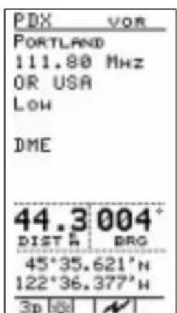

NDB Waypoint Information
• Bearing and distance from present position
- Operating frequency
• Lat/Lon coordinates
• DME available
• Class (high/low/terminal)
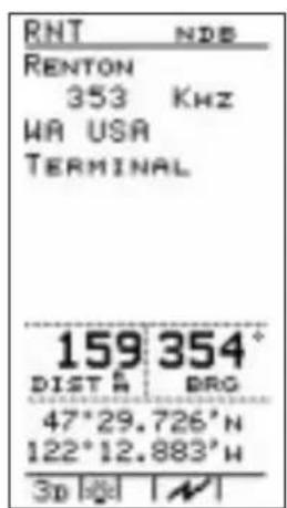

INT Waypoint Information
- Country
• Bearing and distance from present position
• Bearing from present position
• Lat/lon coordinates
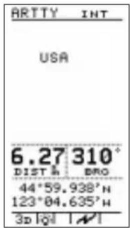

USER Waypoint Information
• Bearing and distance from present position
• Distance from present position
- Lat/Lon coordinates

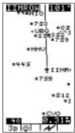
Tutorial
This section gives a tutorial on using the built-in simulator to practice “flying” the Precedus. Use this tutorial at your own pace to become familiar with using the unit.
During the tutorial, you will use many of the Precedus's features as you would during an actual trip. All operating functions are available while you use the simulator. Each will work the same way when you actually navigate later.
Get comfortable and take some time to follow the instructions in this section to “fly” with the Precedus. As you navigate with the simulator, feel free to experiment with the features as much as you like. The instructions here should serve only as a general guide. The goal of this tutorial is to help you become comfortable using the Precedus.
When you finish using the simulator, switch the unit off. The next time you switch it on, simulator mode will be automatically canceled and the unit will be set to aviation mode for actual navigation.
Starting the Simulator

- Press MENU to turn on the Precedus.
- Press the MENU key again to reach the main menu.
- Press the ▼ △ buttons to select "SYSTEM SETUP." Press CENTER select the option.
- Press the ◀ ▶ buttons to select Simulator mode.

- To set your Ground Speed, press the buttons to highlight the Ground Speed value and change it with the buttons to save your settings and continue.

- A message in the Navigation function warns you that GPS data is not available and that positions are simulated.
Preparing for the Trip
Before you navigate a trip, determine whether you will fly direct to a waypoint, or navigate a route of several waypoints. This tutorial presents instructions to set up either kind of trip. It may be helpful to first navigate direct to a destination before setting up a route to travel.
Originating the Trip
The Precedus's simulator uses your present position as the point of origin for the trip unless you have already used the unit to navigate a route. If this is the case, refer to the tutorial section entitled “Navigating a Route” later in this section, or deactivate your route and continue. These exercises assume your present position is the point of origin for the trip.
Assigning a Direct Waypoint
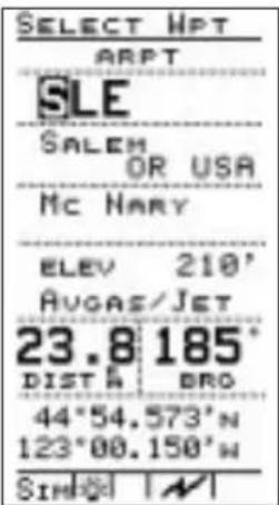
- Press the button.

-
Press ▼ △ buttons to select the first character of the destination waypoint name.
-
Press the ▶ button to move the highlight to the next character of your destination waypoint name.
-
Repeat steps 2 and 3 to select the last character of the destination waypoint name and the waypoint type. Press the ENTER button to assign the waypoint as the destination.

Navigating the Trip
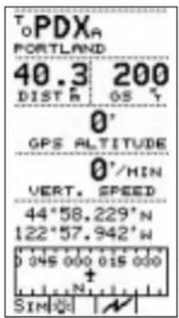
In the Navigation function, your track shows directly on course with no deviation from the bearing to the destination. The Lat/Lon coordinates change to reflect your present position to the nearest hundredth of a minute. The bearing/distance/ground speed show your selected ground speed and estimated time enroute on the trip.
Note
No GPS altitude value shows on the display when you are in Simulator mode.

Looking Around

While viewing the Moving Map, press the location room in and out and see waypoints around you. The map scale shows in the lower left corner of the display and indicates the represented distance between the airplane symbol and the top of the display. For example, if you are 30 nm from your destination and the map scale is set to 30 nm, you should be able to see the destination on the display. If, at the same map scale setting, your destination was 40 nm distant, you would not be able to see it on the display unless you selected a larger map scale.
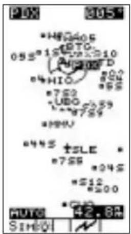
While viewing the moving map screen, press the buttons to change the map scale to "AUTO" to enable the auto zoom feature. Auto zoom shows your destination on the screen and keeps it in view as you navigate your course. The map scale changes automatically to a smaller scale as you approach the destination.
Getting Waypoint Information

While you are enroute, you may want to get information about your destination waypoint. You can check for fuel availability, runway lengths and surface, communication frequencies, and more. With the moving map screen displayed, press the INFO button to get information about the destination waypoint.

Press the buttons to view additional pages of information. Press the INFO button again to return to the moving map screen.
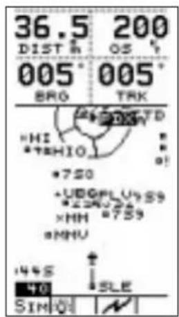
You can also get information about other waypoints on the screen as you navigate, whether or not the waypoint names are displayed. Select a map scale that presents at least several waypoints around you, or use auto zoom. Press the ENTER button several times and watch the highlight move from waypoint to waypoint on the screen.
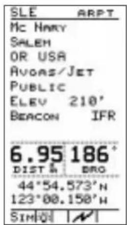
Information about the highlighted waypoint is available when you press the INFO.
Hint
You can get information about any waypoint in the Precedus's built-in database. Follow the steps in "Assigning a Direct Waypoint" earlier.
With the desired waypoint name showing on the display, press the INFO n. Waypoint
information shows on the screen, without the waypoint being assigned as a destination. Press

again to return to the previous function.
Checking Alert Settings

Looking ahead at the destination, the screen shows an airspace around it.
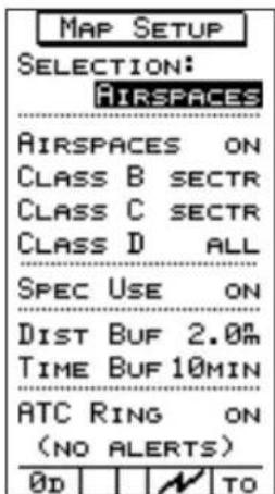
The airspace shows because the Map Setup menu option has the "AIRSPACES" item set to "ON."

You can also select an alert message to show on the display when you approach the airspace.
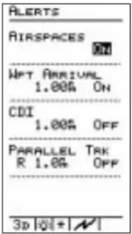
Select the AIRSPACE ALERTS function on the Main Menu. The "AIRSPACES" choice should be set to "ON."
The Precedus can also alert you with a message on the display as you approach your destination. Set the WPT ARRIVAL selection to "ON." Set the distance from the destination where you wish to be alerted.

Select the Airspaces screen under the MAP SETUP function on the Main Menu. Select the TYPE of airspaces, set the distance buffer to the desired distance from the airspace where you wish to be alerted, and the Time Buffer item to the desired travel time (at your present speed) from the airspace where you wish to be alerted. Press ENTER to return to the main menu.
Approaching the Destination

With the destination approaching, the airspace alert message shows on the display at the time or distance from the airspace (whichever occurs first) selected earlier. Press tENTER acknowledge the alert.
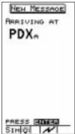
As you approach the destination, the arrival alert message also shows on the display at the distance from the destination you selected. Press t ENTER acknowledge the alert.
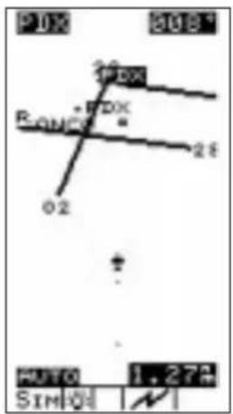
Scroll through the navigation screens to check your progress and decreasing range to the destination. When you are within several miles of the destination, adjust your ground speed to slow your rate of travel to approximately 30 knots. See “Setting the Ground Speed” earlier in this tutorial. Use the moving map screen to view your arrival at the destination. Set the map scale to auto zoom. At this slower rate of travel, you can clearly see the approaching destination. As you approach, you can see the runway configuration.
Note
The simulator will not “land,” but shows a “fly-by” and continues travel at the current heading and ground speed until you enter another destination. When you do this, the heading changes and the unit navigates to the new destination. You can stop travel at any time by adjusting ground speed to 0.

Setting Up a Route
The Precedus can store up to 20 routes or multiple leg trips of up to 30 waypoints each. After you create a route, you can edit it to add or change waypoints anytime. You can also delete waypoints from existing routes. See pages 29-36 in the Navigation Basics section for Route editing details. You can navigate any route you choose, but only one route can be active at any time.

- Display the route screen in the navigation function by pressing the

buttons. From the route screen, select "EDIT" with the <|>|> buttons and press .ENTER


- Use the left to select
"INSERT" to begin inserting waypoints. Press .ENTER
You can select waypoints to insert based on type, identifier, or name.
![ROUTE 01 OFF 01 EUG A 324° 22.7 R 02+CVO A 006° 27.5 R 00 SLE A 005° 44.2 R 04 PDX A RTE OPTIONS ST# NEXT EDIT PUSH ENTER TO START ROUTE SIM[0] [N] SIM[0] [N]](/content/2026/06/1199560/images/a6c1a2b57fcf499cfa7b57805921b88267af054f25210a0686f29ccdd099d9f1.jpg)
- The arrow cursor points to the first line in the route for the first waypoint. Press the buttons to choose the waypoint type (ARPT, VOR, NDB, INT, or User) and then the first character of the waypoint. Press the
buttons to select the desired character.
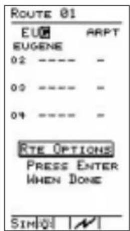
- Press the buttons remove
the highlight to the next character of the name. Repeat steps 3 and 4 to select the last character of the waypoint name and the waypoint type.
Hint
With the highlight on the first character of the
waypoint name, press ◀ and then the


buttons to search the database of waypoints one by one if necessary to find the waypoint you desire. You will need to do this if more than one waypoint share a common name. The vertical

arrow symbol appears to the left of the waypoint name.
![ROUTE 01 OFF 01 EUG A 334° 22.7 R 02+CVO A 009° 27.5 R 00 SLE A 005° 44.2 R 04 PDX A RTE OPTIONS REV NASH GUIT PUSH ENTER TO START NORMAL SIM[0] | N](/content/2026/06/1199560/images/da26de9a33092e1416d2ca697a92cd3b4704dc8593c7204d8fb2f5a0f71b63e6.jpg)
Starting a Route
- Press ENTER to insert the waypoint in the route. The waypoint is inserted and the arrow cursor points to the second line in the route. Repeat steps 2 through 4 above to enter additional waypoints.
When you finish inserting waypoints in the route, select "QUIT" with the
buttons and press . ENTR route is ready to navigate once it is started.
With the route you just created showing on the screen, select "START" with the
buttons and press. ENTER
The arrow marker points to line 02, indicating the "TO" waypoint. Waypoint EUG on line 01 is the point of origin.
You can navigate any route you choose, but only one route can be “Started” or active at any time. You can navigate the route in either direction, depending on your present position. For example, if your present position is at the last waypoint in the route, you could use this last waypoint as the point of origin by selecting “REVERSE.”
With "NORMAL" selected, press . ENTER The route screen shows on the display with the bearing and range to the waypoint at the right side of the screen.
Navigating a Route Set the ground speed to a realistic rate of travel. During route navigation, the arrow marker on the route screen points to the current “TO” waypoint. Scroll through the navigation screens to check your progress on the route.

As you approach the first destination waypoint, the arrival alert screen shows on the display to indicate your proximity to the waypoint. When you arrive at the first waypoint, the simulator changes course automatically to begin the second leg of the trip. The arrow marker on the route screen points to the new “TO” waypoint. Continue navigating the route. Route "Direct To"
While navigating a route, you may find it necessary to alter your trip and proceed "Direct To" a waypoint elsewhere in the list. You can navigate directly to any waypoint in the route, either those behind or those ahead of you.
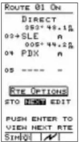
From the route screen, choose the active route. Select "EDIT" with the buttons and press .ENTER the button to move the arrow cursor to the waypoint (or leg) you want. Press .GO TO .NRST . Select the desired waypoint and press ENTER to assign the waypoint as the "Direct To" destination. The route screen shows the assigned waypoint "Direct To" status. You can assign any waypoint in the route a "Direct To" status at any time. Navigation continues to the "Direct To" waypoint.
Track History
The Precedus can store a record of your trip navigation progress in memory. The record consists of a series of track points, each containing your position at the time the point was stored. You can store up to 2,000 track points. Track point storage can be activated or deactivated any time you navigate. Track History cannot be viewed with the Precedus. you will need to use the Waypoint Manager software; contact the factory Technical Service Department.

- Select the Track History option from the main menu. The Track History screen shows on the display.
Press the button to turn "ON" the Track History feature.
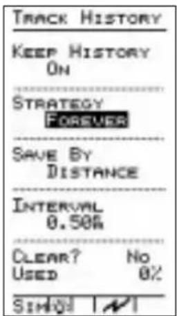
- Press the ▼ button to highlight the strategy type. Select a storage strategy by pressing the button
Select either “FOREVER” or “UNTIL FULL.” The “FOREVER” setting records track points indefinitely, recording over existing track points when memory becomes full. The “UNTIL FULL” setting stops recording points when memory fills to capacity.
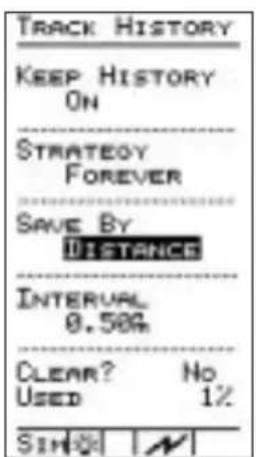
- Press the ▼ button to highlight the storage method. Select a storage method with the ▼ on ▼ choose either “DISTANCE” or “TIME. Press ENTER .
The “DISTANCE” setting records points at the distance interval you select. Similarly, the “TIME” setting records points at the interval of time you select.
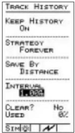
- Select a storage interval for the method you selected. If you selected Distance, the "INTERVAL" will be in nm, sm, or km. If you selected Time, the "INTERVAL" will be in hours and minutes. With the track point history screen items properly set, press ENTER to begin recording.
Note
After you begin recording track points and go about navigating, you can always refer to the Track Point History screen to check how much memory space has been used. Check the "USED" item on the screen to see the percentage of track point storage memory currently used.


- You can move the highlight to the "CLEAR?" item to empty the track point history memory anytime. Select "YES" and press ENTER to delete all track points. Deleted track points are not recoverable.
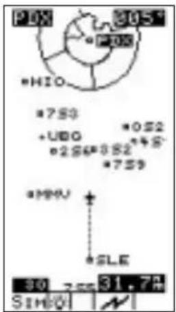
Check the moving map screen in the Navigation function as you navigate the route. With track points being recorded, small dots appear behind the airplane symbol as you travel. Each dot represents a stored track point.
Navigating to a Nearest Waypoint
The Precedus can help you select and navigate to waypoints near your present position. This feature could be valuable if you had to land the aircraft quickly. For the purpose of this tutorial, imagine that the weather conditions were becoming worse and you wish to land immediately.
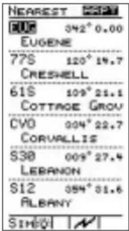
- Press GO TO NRST twice to display up to 30 closest waypoints around you.
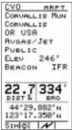
- Press the ▼ button to move down the list to select a waypoint. Press the ◀ buttons to view the airport, VOR, NDB, INT, or USER waypoint categories. Press INFO tamine details about the waypoint that the arrow points to.

- Press GO TO NRST to choose the waypoint as the destination. You will now fly "DIRECT" to your chosen "NEAREST" waypoint.
Conclusion This tutorial has explored many of the Precedus's features. If you feel comfortable using the unit, switch it off and then back on to cancel the simulator. The unit is ready for actual navigation. If you need more time to become comfortable operating the Precedus, repeat this tutorial. Navigate to different destinations, add new routes, and take your time exploring the way the unit works. The way you move the highlight around the screen and select option items is consistent throughout all items on the main menu.
Remember:
• The bowns have the highlight
• The leftmost change highlighted settings
While you navigate, remember:
• The low on change navigation screens
- The ◀ ➕ buttons move the highlight on the GPS signal screen and route screen, and changes the map scale on moving map screens
Troubleshooting
This section contains information to troubleshoot the Precedus when improper operation is observed. The following table lists possible problems you could encounter while operating the unit. Examine the possible causes of the problem and take the action listed to correct the trouble. If you cannot correct the problem, contact your dealer. If your dealer is unavailable, contact the II Morrow factory at the address and phone number listed.
Contacting If efforts to resolve the problem fail, contact your dealer or the Factory the factory weekdays from 8:00 A.M. until 5:00 P.M. Pacific time for technical assistance. The II Morrow technical service staff will gladly assist you.
II Morrow Inc. Technical Service Department 2345 Turner Road S.E. Salem, OR 97302 U.S.A.
U.S.A. Toll Free 800-525-6726 Canada Toll Free 800-654-3415 FAX (503) 364-2138 International (503) 391-3411
Problem Possible Cause Action
| Unit does not power on | If using battery: Dead battery | Recharge battery |
| If using AC power supply: bad power supply | Check operation with battery or a known good power supply | |
| No GPS signal reception | Obstructed signal path | Move aircraft out of hangar or away from buildings to provide an unobstructed view of the sky for the antenna |
| Incorrect seed position, time, or UTC differential entered | Check these settings, if necessary | |
| Unit in simulator mode | Select “Aviation” mode in the “Usage” function in System Setup | |
| If using an external antenna: faulty external antenna, wiring, or connections | Contact your dealer to check the antenna and other wiring | |
| Display too dark or too light — characters hard to see | Change in viewing angle or ambient light conditions | Adjust display backlight or contrast |
| Search for nearest waypoints reveals too few or wrong types of waypoints | Incorrect selection of waypoint types to show after search | Check “Map Setup” function and verify that the desired waypoint type to search is “ON” |
Problem Possible Cause Action
| Wrong types of waypoints show on moving map screens | Incorrect selection of waypoint types to show on moving map screens | See action above - the waypoint types you set to “NO” do not show on the moving map screen or after Nearest Waypoint searches |
| Position fix seems inaccurate | Incorrect Map Datum selected | Check Map Datum selection in System Setup to verify correct map datum |
| Wrong bearing and track values | Incorrect magnetic variation entered | Check Magnetic Var option -select “Automatic” or enter correct value |
| Airspace boundaries missing from moving map | Airspace display on moving map screens set to “OFF” | Check “Map Setup” and set “Airspaces” to “ON” |
| Line representing route path on moving map is missing | Route path display on moving map screens is set to “OFF” | Check the “Map Setup” function and verify that “Route” is set to “ON” |
Glossary of Navigation Terms
A Altitude (GPS ALT): Altitude, as calculated by the Precedus, based upon a mathematical model of the earth's surface curvature. A substantial difference between this altitude value and altitude referenced to sea level may exist.
Automatic Terminal Information Service (ATIS): Recorded information about weather and other conditions at an airport, periodically updated when conditions change.
Azimuth: Bearing, as measured clockwise from true or magnetic north.
B Bearing (BRG): The direction to any point, usually measured in degrees relative to true or magnetic north.
C Constellation: A group of stars or objects, such as GPS satellites, in the heavens.
Coordinates: Values for latitude and longitude that describe a geographical point on the surface of the earth.
Course: The planned direction of travel in a horizontal plane.
Course Deviation: A measurement of distance left or right from the desired course of travel.
Course Deviation Indicator (CDI): A graphic indicator of course deviation typically shown as a graduated horizontal bar with an icon indicating the deviation distance left or right of course.
Common Traffic Advisory Frequency (CTAF)
D Database: A collection of data structured in such a way as to allow quick and convenient access to any particular record or records. The Precedus contains a built-in database of waypoints and waypoint information. Users may add waypoints to this database.
Degree: 1/360th of a circle.
Desired Track (DTK): The desired course of navigation between a point of origin and a destination waypoint.
Dilution of Precision (DOP): A merit value for the calculated position based on the geometrical configuration of the satellites used; 3 is considered good, greater than 7 is considered poor. Also called Precision Dilution of Precision or PDOP.
Distance: A measure of interval in space. Also referred to as range.
Distance Measuring Equipment (DME)
Drift: Displacement from the intended course of travel.
E Elevation: The angle of a GPS satellite above the horizon.
Estimated Time of Arrival (ETA)
Estimated Time Enroute (ETE)
F Fix: A geographical location determined by either visual reference or by electronic navigation aids.
G Global Positioning System (GPS): Also known as NAVSTAR. A constellation of satellites launched by the U.S. Department of Defense into six orbit lanes (four satellites per plane) at an altitude of 10,898 nm above the earth.
Ground (GRND): Ground communication frequency
Ground Speed (GS): Speed of travel across the ground. In aviation, the relation between ground speed and air speed is affected by the prevailing winds.
Icon: A symbol shown on the display depicting present position. The icon is shown as a symbol of an airplane on the Precedus's moving map screens.
Identifier: A name, typically abbreviated, assigned to a waypoint. The identifier may consist of numbers and alpha characters, up to six in length. For example, the airport identifier for Los Angeles International Airport is LAX.
Instrument Flight Rules (IFR)
Intersection (INT): A point defined by any combination of courses, radials, or bearings of two or more navigational aids.
K Knot (kt): A unit of speed equal to one nautical mile per hour.
L Latitude (Lat): Any line circling the earth parallel to the equator, measured in degrees, minutes, and seconds north and south of the equator.
Longitude (Lon): Any line from the north to the south pole, measured in degrees, minutes, and seconds of a circle, east or west of the Prime Meridian (Greenwich, England).
M Magnetic North: The region, some distance from the geographic north pole where the earth's magnetic lines concentrate. A magnetic compass points to the magnetic north.
Magnetic Variation (Mag Var): The angle between the magnetic and true north. At various points on the earth it is different due to local magnetic disturbances. It is shown on charts as isogonic lines marked with degrees of variation, either east or west. These degrees must be added to or subtracted from the true course to get the magnetic course. (Easterly variations are deducted, and westerly variations are added.) The Precedus automatically sets magnetic variation to 0 degrees at positions above 70 degrees north or south latitude.
Map Datum: A mathematical model of the earth used for the purpose of creating navigation charts and maps. The Precedus contains the set of datums listed in Appendix B.
Meter (m): A metric distance measurement equal to 39.37 inches.
Minute: 1/60th of a degree.
N Nautical Mile (nm): A distance measurement equal to 6,076 feet, or 1.15 statute mile. One nautical mile is also equal to one minute of latitude.
Non-Directional Beacon (NDB): A low frequency/medium frequency navigation aid sending non-directional signals that can be used for navigation.
R Radial: Any of the 360 magnetic courses from a VOR or similar navigational aid, beginning at the navigational aid and proceeding outward in a straight line.
Range (RNG): The distance from the present position to a destination waypoint.
S Second: 1/60th of a minute of a degree.
Seed Position: A latitude and longitude position fix approximately equal to the current position that the Precedus uses to determine the location of available satellites from which signals may be received.
Selective Availability (SA): The degradation of accuracy of GPS position fix data by the United States Department of Defense for civilian use.
Statute Mile: A distance measurement equal to 5,280 feet or 0.87 of a nautical mile.
T Three-dimensional (3D) Position Fix: A position fix defined by latitude, longitude, and altitude.
TOT: Total Outside Temperature. Also called indicated air temperature, this is the total temperature of the outside air temperature (TRU) and the heating effect of the aircraft moving through the air. The heating effect is usually negligible for most piston aircraft.
Track (TRK): The imaginary line that the flight path of an airplane makes over the earth.
TRU: True outside air temperature.
True North: Geographic north, at the earth's north pole.
Tower (TWR): Airport tower communication frequency
U UNICOM: The radio frequencies assigned to aeronautical advisory stations for communication with aircraft. Unicoms
may provide such airport information as active runway, wind direction and velocity and other conditions of importance to pilots.
Universal Coordinated Time (UTC): Greenwich Mean Time, or the time at the Prime Meridian in Greenwich, England. Also referred to as Zulu time.
UTC Differential: The difference in time between that at the present position and UTC.
Universal Transverse Mercator Map Projection System (UTM): Also known as Military Grid Coordinates, the UTM grid consists of 60 north-south/east-west zones, each six degrees wide in longitude.
V Very High Frequency Omnirange (VOR): A navigational aid that transmits signals such that a receiver can indicate its current radial or bearing from the transmitter.
W Waypoint: A navigation fix used in area navigation and defined by latitude and longitude coordinates.
Display Care and Cleaning
Your new Precedus GPS has a hard coating that has been applied to the display screen. Despite this coating, care must be taken when cleaning the display screen. To remove stains, smudges, fingerprints, and so forth, we recommend these cleaning methods (if the first method fails to remove the problem, try the next method):
- Wipe with a clean, dry, non-abrasive fabric (for example, cotton or Handi-wipes). Do NOT use paper products, such as paper towels or facial tissues.
- Blow on the area to condense moisture on the display and then wipe the area with the clean fabric
- Moisten a clean fabric with a small amount of water and wipe the display area
- Apply a small amount of glass cleaner (without ammonia) to the fabric and wipe the area
- Apply a small amount of isopropyl alcohol and wipe the area (this is the last resort)
Note

Use a clean fabric with each cleaning method to avoid other contaminants. Do not use paper products.
Battery Care
Charging the Battery The Precedus comes with a high quality rechargeable NiCd battery. This battery is not charged and needs to be charged two to three times to reach full capacity before its first use. A built-in battery charger will charge the battery when the unit is connected to external power.
Charge the battery by connecting the Precedus to external power using either the AC adapter or the cigarette plug. Leave the unit plugged in for a minimum of eight hours. The Precedus will automatically stop charging and maintain the full charge.
Battery Memory The battery may lose some of its capacity if the battery is only partially discharged and then charged again. This loss of capacity is called the memory effect and can be reversed by discharging the battery completely before charging it again. Leave the Precedus on until the battery is completely discharged and then charge the battery to recondition it. A special battery charger/reconditioner available for the Precedus will accomplish this automatically.
Desktop Charger A desktop battery charger/reconditioner is available for the Precedus and will quick-charge the battery in approximately one hour. The desktop charger has a built-in reconditioner that will remove the memory effect from your battery.
Index
A
Airport. 66
Airspace....74,86 Alert....49,65,75 Distance Buffer....46 Time Buffer....47
Airspaces....46
Alert....8
C D I....50
Parallel Track....50
Waypoint Arrival....49
Alerts. 39,49,74 Airspace. 49,65,75 Arrival. 65
Altitude....2 Antenna....15 Approach....37 Arrow Buttons....3
B
Backlight.....5,57,64
Battery Care....92 Charger....92 Memory....92 Memory Effect....92
C
CDI Alert Resolution....50 Scale Default....65 Contacting the Factory....84 Contrast....5,58,64 Controls....3 CountdownTimers....54 Current Date....12 Current Position....12
D
Database Memory....62 Type....62
Default Settings. 64
Differential GPS 59
Dilution of Precision. 20
Display 85
Backlight .... 5
Contrast .... 5
Information .... 5
Startup .... 6
Display Care and Cleaning....91 Display Units....8,39,47,50 Altitude....51 Defaults....65 Distance....51 Lat/Lon....51 Magnetic Variation....51
Distance Buffer Airspace Alert .... 4 6
E
E 6 B....6 2 Enter....3
F
Flight Plan....4 Fixed Map....3 5
G
General Information . . . 40, 48, 61, 65 Databases ..... 6 1 System Info..... 6 2
Glossary....87,90
GOTO....4,16
GOTO....4,16,24
GPS....1
Altitude....72 Satellite....15 Satellites....11,20 Signal....85 Signal Strength....14
Status....14,15,20
Version....62
H
HSI Display....26
I
Identifier Size .... 4 5
II Morrow Inc....84
Info 3
Intersection 68
L
Local Time....13,58
M
Magnetic Variation....50,65,8 Display Units....51
Main Menu8.... 39,40
Map Datum....50,52,64,8
Map Setup....8,28,39,45,65, ATC Ring....47 Road Data....48
Message 75
Messages....20
Moving Map....72,86 Airspaces....46
Auto Zoom. 26
Orientation. 46
Panning 23
Scale....2
Auto Zoom....26
Scanning for WPT Info ..... 30
Screen 23
Serial Data Port ..... 5 9
Zoom 25
N
Navigation Adding Route Waypoints . . . . 3 3
Basics....19
Customizing Information
Screens....21
Deleting Route Waypoints....34
Direct 82
Function....9,19
Function Summary .....60
Information Screens.....19,22
Multiple Leg Flight Plans .... 31
Number of Nav Info Pages ... 60
Return 39
See Route
Route Screen 27
Route Waypoints ..... 3 2
Simulator 69
Summary 9
Trip 72
Trip Setup 71
NDB 67
Nearest 4
...... See Also GOTO
New Waypoint .... 3
NMEA Data Format .... 59
6P
Parallel Track Alert Resolution.....50
Pilot Checklist....42
Checklist Options ..... 4 4
Creating New 42
Edit Existing 43
Position Fix. 20
Power 3
Power Light. 57
Present Position....58,72
R
Return to Nav 8,39
Route
Adding Waypoints....3 3
Changing Waypoints ..... 3 2
Creating 31
Deleting Waypoints....34
Direct "To" 36,79
Hold 35
Normal....78
Resume 36
Reverse 78
Setup 76
Start 78
Starting. 34
Stop 35
V VOR....67
S
Screen/Light5, 9, 40, 57
Backlight 57
Contrast 58
Power Light 57
Status Ligh....t 5 7
Seed Position ..... 9, 11 - 12, 58
Serial Data Port. 59
Serial Output. 65
Simulator....69,70,85
Software Version 62
Status Light. 57
System Info. 9
System Information.....40,61,65
System Setup....9,40,58,85
Differential GPS ....59
Navigation Pages. . . . . . . . . . 6 0
NMEA 59
Serial Data Port ..... 5 9
Simulator 70
Usage 59
W
Waypoint....2-3,86
Airport Information ..... 6 6
Arrival 75
Arrival Alert 49
Arrival Alerts. 65
Available Information ..... 6 6
Creating User Waypoints.....28
Database....16,66-68
Database Structure. . . . . . . . . 6 6
Destination....16,71
Destination Information.....29
Direct....71,74
Getting Information.....73
Information.....27,29-30
Intersection Information ..... 6 8
NDB Information.....67
Nearest. 82,85
Nearest Waypoint
Information 30
Nearest Waypoint Search .... 2 7
User Information ..... 6 8
User Waypoint
Management ..... 29,39,55
VOR Information. . . . . . . . . 6 7
Waypoint. 2,3,86
Creating User Waypoints..24,28
Waypoint Identifier....3
T
Time & Place ..... 9, 12
Time and Place ..... 40, 58, 64
Time Buffer
Airspace Alert .... 47
Timer
Countdown.....8,39,54,65
Track History ..... 8, 39, 55, 65, 80
Troubleshooting....84-86
Tutorial 69-83
U
Usage 58,64,85
User Waypoint
Management....8,39,55,65
Delete. 55
Edit. 5 5
UTC 13,58,85
Precedus Features
- User adjustable character size on the Moving Map
- Customizable Navigation pages
- Extensive built-in database including: Public-Use airports, VORs, NDBs, Intersections, runway diagrams, waypoint information, and U.S./Canada GPS overlay approach waypoints
Segmented special use airspace (U.S. Class B and C; MOAs; Restricted, Prohibited, Warning, Alert, Caution, Danger, and Training area; International Class B and D, CTAs and TMAs.
Frequencies for approach, tower, ground, ATIS, UNICOM, CTAF, etc.
Automatic Approach Monitor; displays GPS overlay approach waypoints
Runway centerline extensions Airport City Search
• 1,000 User-programmable waypoints
- Countdown Timer
• GOTO (Direct-to-Waypoint) function
- Nearest Waypoint Search by Navaid type (airport, VOR, NDB, INT, User)
- Selectable modes optimized for your use:
Aviation
Simulator
Land Mobile
Hiking
Survey
- E6B Calculator functions for: calculated and true airspeed, true air temp, density altitude, indicated altitude, barometric pressure, heading, head wind, wind direction, and wind speed
- Graphic display of GPS satellite location and signal quality
- Parallel Track
- Remote waypoint search
• Differential GPS input
• Automatic and manual magnetic variation - Internal/External antenna
- Interfaces
NMEA 0183
RS-232 compatible with aviation moving maps and radar PC (up/downloading database, user waypoints, and routes
RTCM SC-104 (differential GPS) and more...
Technical Specifications
Display: 80 x 160 pixel (12,800) LCD with electroluminescent backlighting
Viewing area: 1.57 x 2.93 inches
Size: 2.2 inches w x 7.5 inches h x 1.5 inches deep
Weight: 17 ounces
Power: Internal, rechargeable 6.2 volt battery (standard P110 NEC-type cell phone)
Battery Life: 4 hours typical
External: 10-32 VDC
Environmental:
Operating Temperature - -10°C to +60°C
Storage Temperature - -40°C to +70°C
Humidity - 50°C at 95%
Altitude - 40,000 feet
GPS Performance:
GPS Receiver: 8-Channel parallel
Frequency: 1575.42 MHz L1 C/A code
Horizontal Accuracy: 15 meters RMS (100 meters 2 DRMS w/SA
DGPS Accuracy: 1-5 meters typical
Vertical Accuracy: 156 meters 2DRMS w/SA
Velocity: 600 knots
Time to first fix: 20 seconds
Reacquisition: 2.5 seconds
Position Update: 1 second
Standard Accessories
Rechargeable battery
A/C adapter
Yoke Mount
Antenna Extension Cable
User Guide
Quick Reference Guide
Leather case
Optional Accessories
Ballistic nylon carrying case
High capacity rechargeable battery
Desktop battery charger and conditioner
Serial Interface/Waypoint Manager software
Specifications subject to change without notice.
© 1997 by II Morrow Inc.
Printed in the U.S.A. All Rights Reserved.
II MORROW
VISIONARY THINKING TODAY

© 1997 by II Morrow Inc.
2345 Turner Road S.E.
U.S.A.
Phone (503) 581-8101
1-800-525-6726
In Canada 1-800-654-3415
FAX (503) 364-2138
Part #560-0110-04
Rev. A
APOLLO

- Welcome ...
- About This Manual
- Table of Contents
- Introduction to GPS Navigation ..... 1
- Operation Basics .... 3
- Getting Started the First Time....11
- Navigation Basics....19
- Function Reference 39
- Waypoint Database 66
- Tutorial....69
- Troubleshooting....84
- Glossary of Navigation Terms 87
- Display Care and Cleaning....91
- Battery Care....92
- History of Revisions
- Ordering Information
- Important Notice
- FCC Notice
- DOC Notice
- Aviation Applications
- Introduction to GPS Navigation
- GPS System Accuracy
- Summary
- Operation Basics
- Controls
- Display Screens
- Startup Screen
- Main Menu
- Getting Started the First Time
- Note
- Entering a Seed Position
- Important!
- Press the button.
- Select a destination waypoint. Use the
- Hint
- Navigation Basics
- GPS Status
- TO MOVE
- Moving Map Screen
- Important
- Resuming a Route
- Function Reference
- Main Menu Function Summary
- Pilot Checklist
- Creating a New Checklist
- Misc Setup
- Aviation Waypoints
- Airspaces
- Road Data
- All Roads - Choose ON or OFF.
- City Wpts
- Display Units
- System Info
- E6B Functions
- Density Altitude
- Default Settings
- Waypoint Database
- ARPT Waypoint Information
- NDB Waypoint Information
- INT Waypoint Information
- USER Waypoint Information
- Tutorial
- Track History
- Remember:
- Troubleshooting
- Glossary of Navigation Terms
- Common Traffic Advisory Frequency (CTAF)
- Distance Measuring Equipment (DME)
- Instrument Flight Rules (IFR)
- Display Care and Cleaning
- Battery Care
- Index
- A
- B
- C
- D
- E
- F
- G
- H
- I
- L
- M
- N
- 6P
- R
- S
- W
- T
- U
- Precedus Features
- Technical Specifications
- Standard Accessories
- Optional Accessories
- II MORROW
Brand : GARMIN
Model : Apollo 900
Category : Unspecified