
ROKK Nest Qi - Power bank Scanstrut - Free user manual and instructions
Find the device manual for free ROKK Nest Qi Scanstrut in PDF.

| Product Type | Wireless Charger (Qi) |
| Brand | Scanstrut |
| Model | ROKK Nest Qi |
| Output Power | 5W (5V, 1A) |
| Input Voltage Range | 10-30V DC (12V/24V system) |
| Input Current Max | 1.5A |
| Standby Current Draw | < 0.03W |
| Waterproof Rating | IPX6 (front and back) |
| Certifications | Qi, CE, FCC, ROHS |
| Compatibility | Qi-compatible devices (phones, earbuds, etc.) |
| Mounting Type | Flush mount with bezel |
| Included Accessories | Wireless charger module, front bezel, screws (x5 3mm pan head, x4 No6 self-tapping), pocket |
| Max Phone Case Thickness | 3mm |
| Safety Features | Thermal shutdown, reverse polarity protection (via fuse), IPX6 waterproofing |
| Installation Requirement | Professional installation recommended; use silicone sealant for waterproofing |
| Wiring Recommendation | 18 AWG (0.82mm²) for cable extensions; ensure minimum 10V at device |
| Material | Metal housing, high friction top surface |
| Usage Environment | Marine and vehicle applications (avoid hazardous/flammable atmospheres, above waterline) |
| Warranty | Refer to manufacturer; no user serviceable components |
| Environmental Protection | Waste electrical products should be recycled; do not dispose with household waste |
Frequently Asked Questions - ROKK Nest Qi Scanstrut
User questions about ROKK Nest Qi Scanstrut
0 question about this device. Answer the ones you know or ask your own.
Ask a new question about this device
Download the instructions for your Power bank in PDF format for free! Find your manual ROKK Nest Qi - Scanstrut and take your electronic device back in hand. On this page are published all the documents necessary for the use of your device. ROKK Nest Qi by Scanstrut.
USER MANUAL ROKK Nest Qi Scanstrut
Electrical information & installation instructions.
Issue 2
SC-CW-06E
Technical information.
Important.
| Input voltage range | 10-30V DC(12/24V system) |
| Input current max | 1.5A |
| Output power | 5W (5V, 1A) |
| Standby current draw | < 0.03W |
| Waterproof rating | IPX6 front and back |
| Certifications | Qi, CE, FCC, ROHS, |
(ENG) READ THESE INSTRUCTIONS BEFORE INSTALLING THE PRODUCT.
natural_image
Line drawing of a rectangular metal enclosure or housing component (no text or symbols)Pocket x1

Philips No. 2
Screwdriver

natural_image
Isometric line drawing of a rectangular frame with a recessed top and bottom (no text or symbols)Front bezel x1

Drill Bits
5mm (3/16")
2.5mm (3/32")
3mm (1/8")
1 Choose mounting location ensuring there is adequate space behind mounting surface.

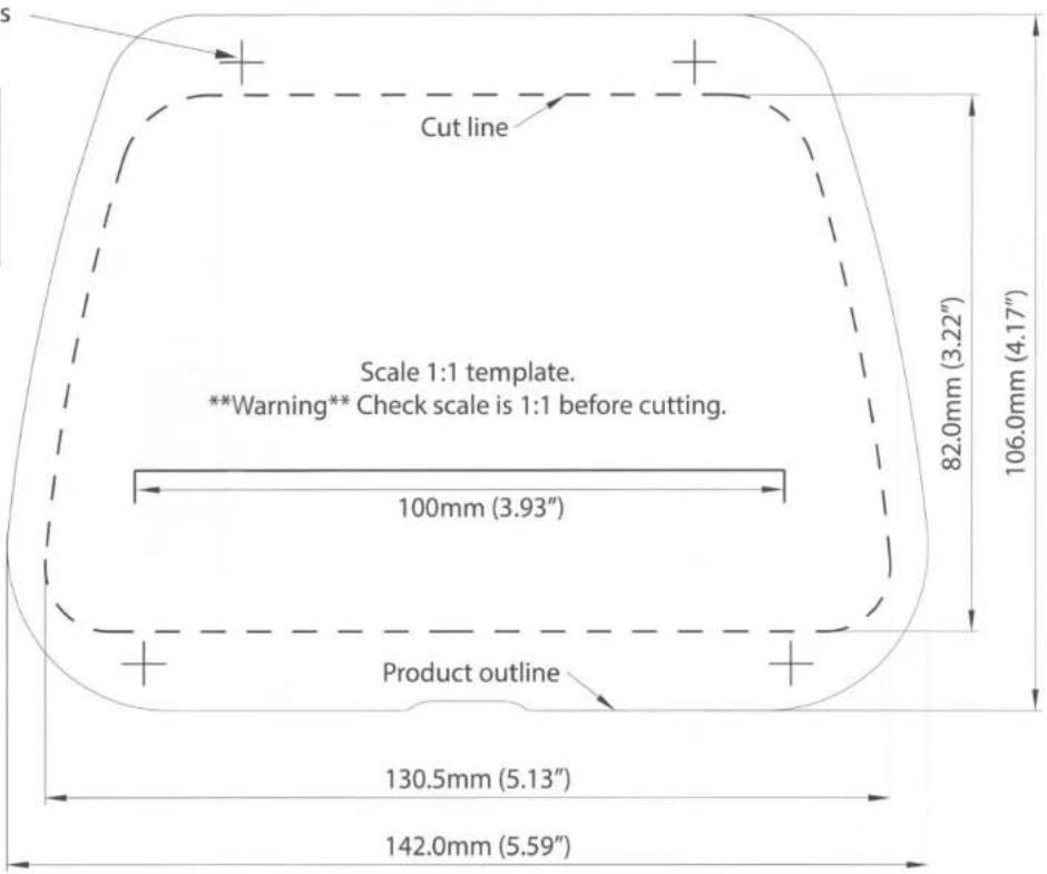
2 Cut hole and drill pilot holes using paper template.

natural_image
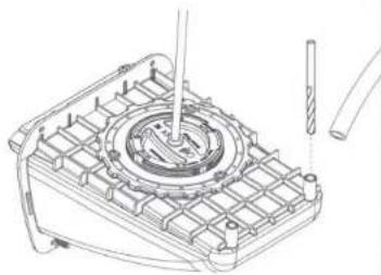
Line drawing of a mechanical component with a rectangular block and internal components (no text or symbols)3 Install wireless charger SC-CW-01E-005 using x3 3mm x 10mm pan head Philips thread forming screws provided.

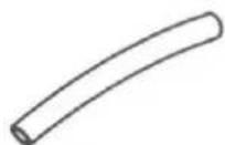
4 Optional Drain Pipe: Carefully drill drain holes using 5mm (3/16") drill bit. Attach drain pipe 8mm (5/16") ID pipe, not included.
natural_image
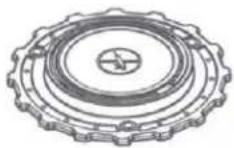
Technical line drawing of a mechanical component with internal gears and a tool (no text or symbols)5 Apply silicone sealant generously around flange, ensure good coverage around perimeter.

natural_image
Line drawing of a mechanical component with a tool inserted, no text or symbols present6 Secure with x4 No8. (3.5mm) x 3/4" (19mm)
Self tapping CSK Philips screws provided.
Add silicone sealant to screw holes.

natural_image
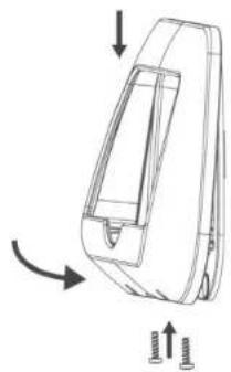
Technical line drawing of a mechanical assembly with screws and a bracket (no text or symbols)7 Attach front bezel using x2 remaining 3mm x 10mm pan head Philips thread forming screws.
natural_image
Line drawing of a car front panel with directional arrows indicating motion (no text or symbols)8 Connect wires to 12/24V supply, ensuring a waterproof connection. Fuse according to input voltage and current.

natural_image
Simple line drawing of a battery connected to a switch and power supply circuit (no text or symbols)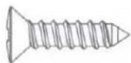
No6 (3.5mm) x 3/4" (19mm) self -tapping CSK Philips screw x4

Powerdrill
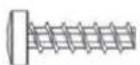
3mm x 10mm Pan head Philips Thread forming screw x5

Jigsaw
SC-CW-01E-005 Wireless charger x1

Silicone Sealant
Drain Pipe 8mm (5/16") internal diameter (Optional, not included)
For latest tech info visit: www.scanstrut.com/rokk-wireless
The product must be installed in accordance with the instructions provided. Failure to do so could result in personal injury, damage to your vessel/vehicle and/or product failure.
Scanstrut recommends installation is carried out by a qualified electrician. No liability is accepted for damage and/or injury caused by incorrect installation.

WARNING
This product is to be fitted to a 12V DC or 24V DC battery/power source only.
The power supply must be switched off before installation.
An appropriate fuse or circuit breaker must be used in-line between the battery/power source and the product.
Check for correct polarity of all wiring before switching the power on.
This product may contain high voltages. Do not tamper with the product.
This product is NOT approved for use in hazardous/flammable atmospheres. Do NOT install in a hazardous/flammable atmosphere e.g. engine rooms.
Before drilling any holes, ensure the area behind the mounting location is clear of wires, fuel and all other hazardous objects.
Ensure any holes cut will not significantly weaken the structure of the surface.
If the product needs to be mounted outside, it must be mounted in a location safely above the waterline, where it is not at risk of being submerged.
The product cannot charge through a metallic surface.

CAUTION
The product is specifically for the charging of Qi compatible devices.
The cable must be retained and not interfere with mechanical systems.
This product contains no user serviceable components. Do NOT attempt to repair or alter the product in any way.
The high friction top surface does not ensure the device will not slip during
extreme operating environments such as high acceleration and deceleration.
If a phone case which is thicker than 3mm is used the device may not charge.
When used in a high ambient temperature/direct sunlight the product may temporarily shut down, this is a safety feature of the electronics.
The IP rating is only valid if correctly installed using the instructions and on a perfectly flat non-porous smooth surface.
When selecting a mounting location, avoid places exposed to heat-radiating appliances and poorly-ventilated areas.
EMC INSTALLATION GUIDELINES
Scanstrut products conform to Electromagnetic Compatibility (EMC) regulations, to ensure that electromagnetic interference between equipment is minimised.
WIRING
When extending the cable from your battery/power source to the product, ensure there is a minimum of 10V being provided to the product continuously. We recommend a wire gauge of 18AWG (0.82mm²) for any length of cable extension.
This schematic is to illustrate how the product should be connected to a 12V DC or 24V DC battery/power supply.
ENVIRONMENTAL PROTECTION

Waste electrical products should not be disposed of with household waste. Please recycle where facilities exist. Check with your Local Authority or retailer for recycling advice.
Drill x4 holes for No.6 Screws
| Material | No. 6 Screw |
| Soft Materiale.g. plywood | 2.5mm(3/32") |
| Hard Materiale.g. fiberglass,acrylic, hardwoods | 3mm(1/8") |
FCC Warning Statement
Changes or modifications not expressly approved by the party responsible for compliance could void the user's authority to operate the equipment. This equipment has been tested and found to comply with the limits for a
Class B digital device, pursuant to Part 13 of the FCC Rules. These limits are designed to provide reasonable protection against harmful interference in a residential installation. This equipment generates uses and can radiate radio frequency energy and, if not installed and used in accordance with the instructions, may cause harmful interference to radio communications. However, there is no guarantee that interference will not occur in a particular installation. If this equipment does cause harmful interference to radio or television reception, which can be determined by turning voice by one or more of the following measures:
Reorient or relocate the receiving antenna.
Increase the separation between the equipment and receiver.
Connect the equipment into an outlet on a circuit different
from that to which the receiver is connected.
Consult the dealer or an experienced radio/TV technician
for help
Brand : Scanstrut
Model : ROKK Nest Qi
Category : Power bank