
PCP700/1SDXA - Hot plate CANDY - Free user manual and instructions
Find the device manual for free PCP700/1SDXA CANDY in PDF.

| Product Type | Gas hob (stove) |
| Brand | Candy |
| Model | PCP700/1SDXA |
| Dimensions (W x D) | 695 x 510 mm |
| Cutout Dimensions | Refer to Fig. 1 (manual) |
| Power Supply | 230 V / 50 Hz |
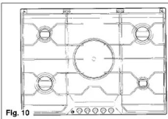
| Number of Gas Burners | 5 |
| Burner Configuration | 1 small, 1 medium, 2 large, 1 double ring (wok) |
| Gas Types | Natural gas (1.0 kPa) and LPG (2.75 kPa) - convertible |
| Electric Ignition | Yes (built-in spark ignition) |
| Gas Safety Device | Yes (thermocouple cutoff) |
| Installation Type | Built-in (worktop cutout) |
| Materials | Stainless steel, enamelled parts |
| Cleaning Instructions | Warm soapy water; avoid abrasives. Burners cleanable with soapy water. |
| Safety Features | Flame failure device, child supervision warning |
| Warranty | 12 months |
| Spare Parts Availability | Injectors, burner caps, control knobs, gas taps |
Frequently Asked Questions - PCP700/1SDXA CANDY
User questions about PCP700/1SDXA CANDY
0 question about this device. Answer the ones you know or ask your own.
Ask a new question about this device
Download the instructions for your Hot plate in PDF format for free! Find your manual PCP700/1SDXA - CANDY and take your electronic device back in hand. On this page are published all the documents necessary for the use of your device. PCP700/1SDXA by CANDY.
USER MANUAL PCP700/1SDXA CANDY
EN HOBS 70 cm USER INSTRUCTIONS
TECHNICAL CHARACTERISTICS
| Cooking hobs 70x50 | |||||||
| Burners 5 gas 5 gas 5 gas 5 gas 5 gas | gas | ||||||
| Reference type P751 P751 P752 P752 P752 | |||||||
| Supply Voltage (W/Hz) | 230/50 | 230/50 | 230/50 | 230/50 | 230/50 | 230/50 | |
| Installed electric power (W) | - | - | - | - | - | - | |
| Medium burner | 1 | 1 | 1 | 1 | 1 | 1 | |
| Large burner | 2 | 2 | 2 | 2 | 2 | 2 | |
| Small burner | 1 | 1 | 1 | 1 | 1 | 1 | |
| Double ring burner | 1 | - | - | 1 | - | - | |
| Maxi burner | - | 1 | - | - | 1 | - | |
| Fish burner | - | - | 1 | - | - | 1 | |
| Power of gas installed: | |||||||
| - Natural gas 1.0 kPa (MJ/H)** | 40,5 | 40,5 | 40,5 | 40,5 | 40,5 | 40,5 | |
| - LPG gas 2.75 kPa (MJ/H) | 37,4 | 37,4 | 37,4 | 37,4 | 37,4 | 37,4 | |
| Electric ignition* | yes | yes | yes | yes | yes | yes | |
| Gas safety device | - | - | - | yes | yes | yes | |
| Product size mm. | 695x510 | 695x510 | 695x510 | 695x510 | 695x510 | 695x510 | |
| Degree protection | - | - | - | - | - | - | |
| Class | 3 | 3 | 3 | 3 | 3 | 3 | |

Fig. 1
* Some models only
** Manufacturer setting
INSTALLATION
The Purchaser is responsible for the installation of the hob. The Manufacturer does not accept any responsibility for any damage or loss resulting from incorrect installation, and as such this will not covered by the Manufacturer's Guarantee.
The hob may be installed in any worktop which is heat resistant to a temperature of 100^ , and has a thickness of 25 - 40 mm. The dimensions of the insert to be cut out of the worktop are in shown in Fig. 1.
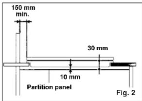
If the Hob is fitted next to a cabinet on either side, the distance between the Hob and the cabinet must be at least 150 mm (see Fig. 2); while the distance between the hob and the rear wall must be at least 55 mm.
If below the hob there is an accessible space, there must be a partition panel in insulating material (wood or similar) providing a space of at least 10 mm below the Hob (see Fig. 2).
The Hob unit is fitted by attaching the Fixing Clamps supplied, using the holes at the base of the unit.
VERY IMPORTANT - APPLYING THE SEALANT
Important - The diagram below shows how the sealant should be applied.
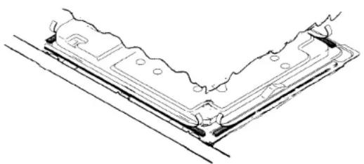
natural_image
Technical line drawing of a mechanical component with mounting holes and a V-shaped groove (no text or symbols)This appliance has been designed for non-professional, i.e. domestic, use.
Appropriate checks and tests have ensured that, even in the most extreme conditions, the temperatures reached are within acceptable limits. The Hob is thermally insulated (in line with Regulation EN) and may be installed: next to panels higher than the worktop, for type «Y», or next to panels not higher than the worktop for type «X». See technical characteristics table «Degree of protection».
Instructions for the installer
Suitable location
A gas-powered cooking appliance produces heat and himidity in the area in which it is installed. For this reason you should ensure good ventilation either by keeping all natural air passages open or by installing an extractor hood with an exhaust flue (Fig. 3-4). Intensive and prolonged use of the appliance may require extra ventilation, such the opening of a window or an increase in speed of the electric fan, if you have one.
If your appliance is not fitted with a thermocouple (safety device) the ventilation hole shown in Fig. 3 should be at least 200 cm ^4 .

If a hood cannot be installed, an electric fan should be fitted to an outside wall or window as long there are air vents in the area.
The electric fan should be able to carry out a complete change of air in the kitchen 3-5 times every hour.
The installer should follow the relevant national standards.

natural_image
Diagram of a kitchen sink with a lamp and brick wall, labeled Fig. 4 (no text or symbols on the diagram itself)Electrical connection
Check the data on the rating plate, located on the outside of the unit, to ensure that the supply and input voltage are suitable.
Before connection, check the earthing system.
By Law, this appliance must be earthed. If this regulation is not complied with, the Manufacturer will not be responsible for any damage caused to persons or property. If a plug is not already attached, fit a plug appropriate to the load indicated on the rating plate. The earth wire is coloured yellow/green.
Where the Hob is connected direct to the electricity supply, a circuit breaker must be fitted with at least a 3 mm contact spacing when in the open position.
It if is necessary to replace the connecting cable, the earth wire (yellow/green) must, by law, be approximately 10 mm longer than the live and neutral wires. Rubber insulated cable type H05RR-F must be used.
The cables should be 1.5 mm ^2 section for products with electrically heated elements,
and 0,75 mm ^2 for others products. Also, the maximum external diameter of the cable should not be greater than 7 mm.

flowchart
graph LR
    A["MAINS SUPPLY"] --> B["LIVE L"]
    A --> C["EARTH"]
    A --> D["NEUTRAL N"]
    B --> E["BROWN WIRE"]
    C --> F["GREEN YELLOW WIRE"]
    D --> G["BLUE WIRE"]
    E --> H["POWER CABLE"]
    F --> H
    G --> H
Declaration of compliance. The parts of this equipment which are designed to come into contact with foodstuffs, comply with EEC directive 89/109.

Appliance complying with European directives 89/336/EEC, 90/396/EEC, 73/23/EEC and subsequent modifications.
Gas connection
The rating plate on the hob shows the type of gas with which it is designed to be used. It is possible to use other types of gas after carrying out some simple modifications. a) Connection to the gas supply
— connection to the mains gas supply or gas cylinder should be carried out according to the relevant national standards, after having checked that it is regulated for the type of gas with which it will be supplied. If it is not correctly regulated follow the instructions in the paragraph entitled «Adaption for different types of gas». For liquid gas (cylinder gas) use pressure regulators which comply with the relevant national standards. N.B.: for safe operation, economic use of energy and to ensure greater durability of the appliance, make sure that the supply pressure conforms with the values shown in the table on page 6.
— Connection to a rigid pipe (see instruction on page 10)
Connection to the gas supply should be done without putting any kind of stress on the appliance.
— Connection to a flexible steel pipe (see instructions on page 10)
The junction of the gas pipe with the appliance is a 1/2" gas tapered thread connection. Use only pipes, washers and sealing washers which comply with the relevant national standards.
The fitting of these pipes should be done to that their maximum length, when fully extended, should not exceed 2000 mm.
N.B.: carry out a final check for leaks on the pipework using a soapy solution. Never use a flame. Also, make sure that the flexible pipe cannot come into contact with a moving part of the cabinet (eg, a drawer) and that it is not situated where it could be damaged.
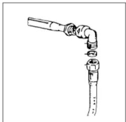
natural_image
Line drawing of a pipe joint with attached fittings (no text or symbols)Adapting the hob to different types of gas
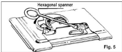
To adapt the Hob for use with different types of gas, carry out the following instructions: — remove the grids and burners
— insert the hexagonal spanner (supplied) into the burner support (Fig. 5)
— unscrew the injector and replace it with one suitable for the gas to be used (see Table page 6).
When you have carried out the new gas regulation, replace the old gas rating plate on your appliance with one (supplied with hob) suitable for the type of gas for which it has been regulated.
REGULATING THE BURNERS
Flame Combustion
For maximum efficiency from the burners, the correct combustion of the flame is necessary. A good flame must be well aligned and without yellow tips (Fig. 7/B). If there is insufficient air, the flame will be uneven with yellow tips (Fig. 7/A). If there is too much air, the flame will be very short and bright (Fig. 7/C). In these cases the combustion must be adjusted by re-fitting the carburation tube to the Venturi (where there is insufficient air) or removing the carburation tube (in the case of too much air). To position the carburation tube, the fixing screws must be loosened, and retightened when the satisfactory combustion is obtained.
For dimensions «X» see attached table
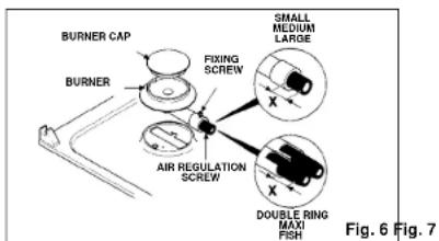
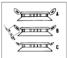
Table of gas consumption
| Burner | Natural gas Reg. 1,0 kPa | LPG gas Reg. 2,75 kPa | Quota +X+ depending on type of gas | |||
| MJ/Hinjector | size | MJ/Hinjector | NG ar regul. | LPG ar. regul. | ||
| Maxi | 2x110 11 | 2x85 11 | 13 mm 13 mm | |||
| Fish | 2x110 11 | 2x85 11 | 15 mm 15 mm | |||
| Double ring | 2x110 11 | 2x85 11 | 13 mm 15 mm | |||
| Rapid | 141 10 | 81 8,7 | 4 mm 5 mm | |||
| Semi rapid | 110 5,7 | 65 5,5 | 2 mm 7 mm | |||
| Small | 92 3,8 | 52 3,5 | 6 mm 6 mm | |||
| Total NHGC | 40,5 | 37,4 | ||||
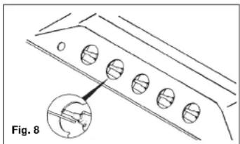
Regulating the minimum flame
After lighting the burners, turn the control knob to the minimum setting and then remove the knob (this can easily be removed by apply a gentle pressure).
Using a small «Terminal» type screwdriver the regulating screw can be adjusted as in Fig. 8. Turning the screw clockwise reduces the gas flow, whilst turning it anticlockwise increases the flow – Use this adjustment to obtain a flame of approximately 3 to 4 mm in length and then replace the control knob.
If GPL (cylinder) gas is being used, turn the screw clockwise right to the end of the travel of the by-pass.
Screws
regulating
Gas tap calibrating screws
(flat head slot type)
PRESSURE ADJUSTMENT
First turn the gas off to the appliance. Remove the sealing screw from the regulators test point at the rear of the appliance and fit the hose of the Manometer to it.
Turn the gas on and light the Wok Burner and one Medium Burner at maximum setting. Check the pressure and adjust at the regulator if necessary to the settings in the table below or on the Data plate.
For Propane Gas adjust at the regulator on the cylinder - Turn regulator adjusting screw clockwise increases pressure whilst anti-clockwise decreases pressure. Refit the test point sealing screw when finished.
INSTRUCTIONS FOR USE
Using the gas Burner
To ignite the burners, place a lighted taper close to the burner, press in and turn the control knob anti-clockwise.
If the burners have not been used for a couple of days, wait for a few seconds before lighting the burner, this will allow any air present in the pipes to escape.
For appliances equipped with electronic ignition, simply press down and turn the control knob to the position marked with a star *.
After the burner ignites, turn the knob to the control setting required.
The ignition is by repetitive spark generation; in case the burner does not light at once, keep the knob in the ignition position for a maximum of 5 seconds.
If the burner does not ignite in this time, switch off the control knob and repeat the operation again.
As a safety device, some models automatically cut off the gas supply if the flame is accidentally extinguished. In this case, push and rotate the control knob until the ★ position and keep it held down for approx 5-6 seconds.
The burner will then remain lit.
ATTENTION: When cleaning the hob, take care to replace the burners correctly, this will ensure that the ignition point is not blocked.
GENERAL ADVICE
For the best results, the flat-bottomed pans size should match the gas burner size as follows:
Small from 6 to 12 cm.
— Medium from 12 to 18 cm. — Large from 18 to 24 cm.
— Double ring from 24 to 28 cm. — Maxi from 24 to 28 cm.
— Fish from 26 to 28 cm.;
Rectangular pan max 210x370 - min. 150x290 mm.
For smaller containers the gas burner should be regulated so that the flame does not overlap the base of the pan. Vessels with concave or convex base should not be used. WARNING: If a burner is accidentally extinguished, turn the knob to the off position and do not attempt to re-ignite if for at least 1 minute.
To protect the glass lid from damage and in the interests of safety, the burners/plates must be turned off and the burner/pan support/plate area must be cool before closing the lid down.
Mijorose burner: the heat diffusing plate, to be used only on the rear right hand burner, is designed to provide a particularly delicate cooking facility. When this facility is not required, the burner can be used in the conventional way.
Use of electric hotplates (electric hotplates)
For the best use of the electric hotplates and to minimise energy consumption, the following recommendations should be noted.
| POWER OUTPUT - ELECTRIC HOTPLATES | ||
| Setting | ||
| 0 OFF | ||
| 1 VERY LOW Warming dishes & melting butter and chocolate | ||
| 2 | LOW | Simmering, sauces, stews, milk puddings, poached eggs |
| 3 | MODERATE | Vegetables, frozen foods, boiling water |
| 4 | MEDIUM | Fresh Vegetables, pasta, fish, pancakes. |
| 5 | HIGH | Omelettes, steaks |
| 6 | VERY HIGH | Chops |
A neon indicator light adjacent to the control knob will glow when the electric plate is in use.
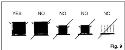
Only pans which have smooth flat bases should be used on the electric hotplates. The size of the pan should be as close as possible to the diameter of the hotplate, and never smaller (see Fig. 9). The base of the pan should be dry and spillages should be avoided. Empty pans should not be left on the plates, nor should the plates left switched on without a pan.
THE GAS HOBS WITH ONE ELECTRIC PLATE ARE FITTED WITH A PAN SUPPORT TO BE USED FOR RESTING PNA WHEN THE PLATE IS NOT IN USE.
WHEN THE HOTPLATE IS SWITCHED ON THE PAN SUPPORT MUST BE LIFTED UP TO ALLOW THE PAN TO BE PLACED IN DIRECT CONTACT WITH THE HOTPLATE.
natural_image
Technical drawing of a mechanical part with grid lines and circular features (no text or symbols)MAINTENANCE AND CLEANING
Important Advice
Before cleaning the Hob, ensure the appliance has cooled down. Remove the plug from the socket or (if connected directly) switch off the electricity supply.
When cleaning the enamelled, varnished or chrome sections, use warm soapy water or a non caustic detergent. For stainless steel use an appropriate cleaning solution. Hotplates should only be cleaned with a cotton cloth coated with vaseline or seed oil. Never use abrasives, corrosive detergents, bleaching agents or acids. Avoid any acid or alkaline substances (lemon, juice, vinegar etc.) on the enamelled, varnisched or stainless steel sections.
The burners can be cleaned with soapy water. To restore their original shine, use a household stainless steel cleaner. After cleaning, dry the burners and replace.
It is important the Burners are replaced correctly.
The appliance is not intended for use by young children or infirm persons without supervision. Young children should be supervised to ensure that they do not play with the appliance.
This appliance must only be used for the purpose for which it is intended, domestic cooking, and any other use will be considered improper and could therefore be dangerous. The Manufacturer will not be responsible for any damage or loss resulting from improper use.
Lubricating the gas taps
If a gas tap becomes stiff, it should be dismantled, cleaned carefully with petrol and smeared with a drop of special heat resistant grease.
The following operations should be carried but:
— disconnect the electrical power supply, close the gas supply tap from the mains or cylinder.
— Remove the hob top plate by removing the corner screws and those under the burners.
— Remove the two screws holding down the head flange.
— Remove the head flange and the retaining spring on the knob shaft.
— Remove the gas regulation cone, clean it with petrol and smear it with some heat resistant grease, taking care not to obstruct any holes through which gas must pass.
— Re-assemble all the parts, making sure that the spring and the rotating axis of the cone fitted to the knob shaft are correctly seated.
Aftercare
Before calling out a Service Engineer please check the following:
— that the plug is correctly inserted and fused;
— that the gas supply is not faulty.
If the fault cannot be identified:
switch off the appliance — do not tamper with it — call the Aftercare Service Centre.
The appliance is covered by a 12 month Guarantee giving free Aftercare Service.
The Manufacturer will not be responsible for any inaccuracy resulting from printing or transcript errors contained in this brochure. We reserve the right to carry out modifications to products as required, including the interests of consumption, without prejudice to the characteristics relating to safety or function.
INSTRUCTIONS FOR ASSEMBLY OF THE HOB TO THE GAS SUPPLY PIPES
These instructions are for Fitters qualified for installation of equipment in line with the relevant national standard. All work must be carried out with the electricity supply disconnected.
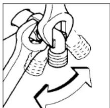
ASSEMBLY PROCEDURE
2 Spanners, sizes 17 and 23 mm are required.

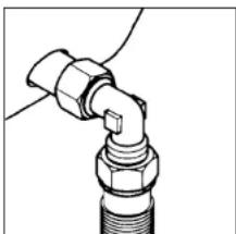
A) As illustrated, assemble parts in sequence:
A) fixed pipe
B) washer
C) Elbow fitting with
tapered thred
connection
natural_image
Diagram of a rope knot being lifted by a rope, showing rope routing and motion direction (no text or symbols)2) Tighten the joints with the Spanners, remembering to twist the pipes into position before tightening.
natural_image
Technical line drawing of a mechanical joint or connector (no text or symbols)3) Attach fitting C to mains gas supply using rigid copper pipe or flexible steel pipe.
VERY IMPORTANT
For ease of installation and to avoid gas leaks, it is recommended to connect the pipes as follows:
First connect the pipe to the Hob
and then
Connect the pipe to the gas supply.
In this sequence is not followed, there is a danger that gas will be trapped in the pipe.
AFTER INSTALLATION, CHECK THE TIGHTNESS OF ALL JOINTS USING A SOAPY SOLUTION

Grafica R.B. - 02/2002 - Cod. 41003881
- INSTALLATION
- Instructions for the installer
- Suitable location
- Electrical connection
- Gas connection
- Adapting the hob to different types of gas
- REGULATING THE BURNERS
- Flame Combustion
- Regulating the minimum flame
- Screws
- regulating
- PRESSURE ADJUSTMENT
- INSTRUCTIONS FOR USE
- Using the gas Burner
- ATTENTION: When cleaning the hob, take care to replace the burners correctly, this will ensure that the ignition point is not blocked.
- GENERAL ADVICE
- Use of electric hotplates (electric hotplates)
- MAINTENANCE AND CLEANING
- Important Advice
- Lubricating the gas taps
- Aftercare
- INSTRUCTIONS FOR ASSEMBLY OF THE HOB TO THE GAS SUPPLY PIPES
- ASSEMBLY PROCEDURE
- VERY IMPORTANT
Brand : CANDY
Model : PCP700/1SDXA
Category : Hot plate