
M3WHM - Microphone Audix - Free user manual and instructions
Find the device manual for free M3WHM Audix in PDF.

| Product Type | Ceiling Microphone Array |
| Brand | Audix |
| Model | M3WHM |
| Microphone Type | Condenser (electret) |
| Polar Pattern (per element) | Cardioid |
| Number of Elements | 3 (120° spacing) |
| Frequency Response | 50 Hz – 20 kHz (typical) |
| Phantom Power Requirement | 18–52 V DC |
| Output Connector | 7-pin mini XLR (male) |
| Included Cable Length | 4 ft (1.2 m) |
| Coverage Radius | Up to 10 ft (3 m) |
| Recommended Mounting Height | 8–8.5 ft (2.4–2.6 m) AFF |
| Included Accessories | Junction box (JBM3), breakout cable (terminal block), seismic restraint cable, lid |
| Optional Breakout Cable | CBLM3XLR (RJ45 to 3 XLR male) |
| Optional Interface Cable | CAT7 LS0H, lengths from 7 to 100 m (prepackaged or bulk) |
| Optional Brass Bell Housing | PLENHSEM3 (plenum seal) |
| Mounting Type | Suspended ceiling (drop tile) |
| Material | Housing: metal (painted); Junction box: plenum-rated metal |
| Color | White (standard) |
| Weight (microphone only) | Approx. 0.5 lb (0.23 kg) |
| Dimensions (microphone) | Diameter: 3.5 in (89 mm); Height: 2.0 in (51 mm) |
Frequently Asked Questions - M3WHM Audix
User questions about M3WHM Audix
0 question about this device. Answer the ones you know or ask your own.
Ask a new question about this device
Download the instructions for your Microphone in PDF format for free! Find your manual M3WHM - Audix and take your electronic device back in hand. On this page are published all the documents necessary for the use of your device. M3WHM by Audix.
USER MANUAL M3WHM Audix
natural_image
Modern office meeting room with a long wooden table, chairs, and large windows under ceiling lights (no visible text or symbols)AUDIX M3 INSTALLATION GUIDE
Thank you for choosing Audix! Our products are designed to provide you with many years of reliable service. Please read this manual before using the system for optimal installation and operation.
IN THE PACKAGE
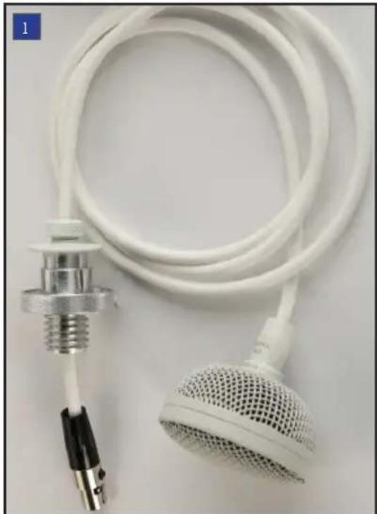
natural_image
Close-up of a white medical or laboratory device with coiled tube and meshed head (no visible text or symbols)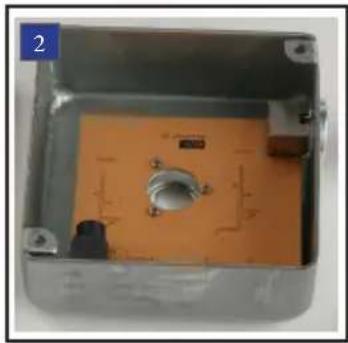
natural_image
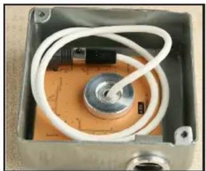
Interior view of an open electronic device casing with orange circuit board and small components (no visible text or symbols)
natural_image
Square metallic object with four small screws, no visible text or symbols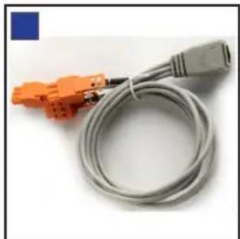
natural_image
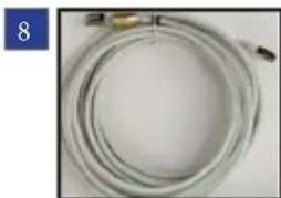
Coiled gray cable with orange connectors, no visible text or symbols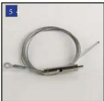
natural_image
Coiled metal wire with a metal rod and tip, labeled '5 4' in the top-left corner (no other text or symbols)1 M3 Tri-element Hanging Ceiling Microphone
2 JBM3 - Plenum rated junction box circuitry
3 Junction box lid
4 Breakout cable consisting of RJ45 female to three terminal block connectors
5 Seismic / Fire restraint cable
OPTIONAL ACCESSORIES

natural_image
Close-up of a brass-colored cylindrical object with rounded ends, no visible text or symbolsPLENHSEM3 Brass plenum bell housing (patent pending). This brass housing is specifically designed to provide a plenum seal when threaded on to the plenum junction box. The bell housing is included with all Audix CAT 7 prepackaged interface cables (see below for models), and may be purchased separately for bulk cable runs.

natural_image
Coiled cable with connectors and connectors, no visible text or symbolsCBLM3XLR Breakout cable consisting of an RJ45 female to three XLR male connectors. This cable is designed to be used in conjunction with Audix CAT 7 interface cable, keeping the shielded and balanced audio path intact when connecting to the three mic level XLR inputs of a DSP Controller.
natural_image
Coiled white cable or hose with a small metallic connector, no visible text or symbolsCAT7 Interface cable. Audix manufactures a high quality CAT 7 cable optimized for balanced audio and cross talk elimination. The cable is LS0H (low smoke zero halogen) and consists of four twisted pairs that are individually shielded, RJ45 male connectors and a brass housing to further seal the cable at the plenum rated junction box. The interface cable is available in prepackaged lengths or in bulk (see below for models).
CBLM307 - Interface Cable 7 meters (23')
CBLM310 - Interface Cable 10 meters (33')
CBLM315 - Interface Cable 15 meters (49')
CBLM320 - Interface Cable 20 meters (66')
CBLM325 - Interface Cable 25 meters (82')
CBLM330 - Interface Cable 30 meters (98')
CBLM350 - Bulk cable. 50 meters (162'). Use with brass plenum bell housing #6 for best results.
CBLM3100 - As above. 100 meters (325')
Note: The Audix M3 also works with CAT 5 and CAT 6 cable, however, Audix recommends using shielded cable.
INSTALLATION AND WIRING INSTRUCTIONS
natural_image
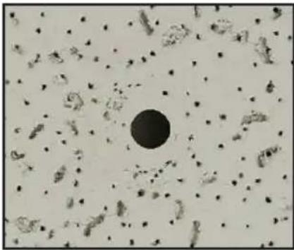
Microscopic view of cellular structures with a central dark circle (no text or labels visible)Fig A. Remove ceiling tile and drill 5/8" (16mm) hole in the desired location.

natural_image
Metal enclosure with internal components and a small central component (no visible text or symbols)Fig B. Position the JBM3 plenum rated junction box 2 over the drilled hole.
natural_image
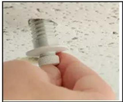
Close-up of a hand holding a metallic screw and nut against a textured white surface (no text or symbols visible)Fig C. Remove the nut from the threaded portion of the M3 cable 1, feed cable through the tile hole and into the junction box.
natural_image
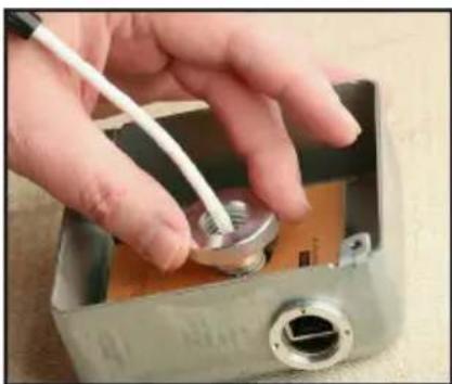
Hand inserting a small metallic component into a metal enclosure with a white cable (no visible text or symbols)Fig D. Install the threaded nut with shoulder side down and secure.

natural_image
Hand inserting a small component into an open metallic housing (no visible text or symbols)Fig E. Insert the 7 pin mini female XLR connector into the male receptacle.
natural_image
Interior view of an electronic device housing with white cables and a central component (no visible text or symbols)Fig F. Set the initial height of the M3 and spool the excess cable inside the junction box.

natural_image
Close-up of a metallic electronic device with a metallic connector and gold connector attached (no visible text or symbols)Fig G. Fasten the lid 3 on top of the junction box. Insert RJ45/Cat cable into JBM3 receptacle. (See back page for installing seismic cable)

natural_image
Hand inserting a small metallic connector into a metal housing (no text or symbols visible)Fig H. If using Audix Cat 7 LSOH interface cable 8, screw on the brass bell housing over the RJ45 connection and reset ceiling tile.

natural_image
Hand holding a metallic stand with red arrows indicating upward motion, against a textured wall background (no text or symbols)Fig I. Adjust the cable to exact desired length by either feeding or pulling the cable through the ceiling mount.
natural_image
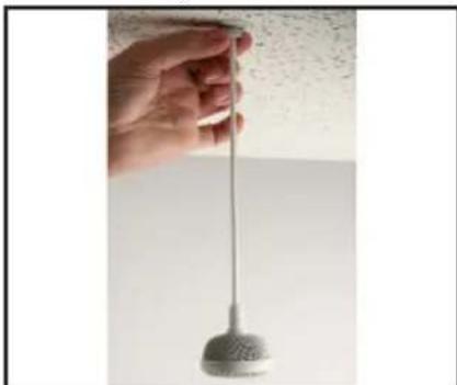
Hand holding a metallic pendulum against a plain wall (no text or symbols visible)Fig J. Position the microphone by turning the cable as necessary and gently turn the nut clockwise to secure (1 to 2 turns). Do not over tighten.

Fig K. Microphone elements are spaced 120 degree apart. Channel 1 is directly below the Audix logo

natural_image
Coiled network cable with orange connectors and a green terminal block (no visible text or symbols)Fig L. Connect RJ45 cables into the breakout cable and connect to DSP Controller.
The M3 contains three independent microphones and audio channels for interfacing into the mixing device or audio console. The Audix provided breakout cable 4 is designed to interface with a professional DSP controller using terminal blocks.
Audix has an optional breakout cable 7 that terminates with three XLR connectors.
The M3 microphone requires phantom power voltage of 18-52 volts.
Microphone Placement
Although the M3 can be hung from a variety of heights, Audix recommends 8' to 8 12 ' AFF (above finished floor) placement. When capturing larger zone areas such as open seating or distance learning, the M3 has a coverage radius up to 10'. Most conference table type coverage, however, will typically utilize a smaller radius. For example: for a 10' - 12' conference table two M3 microphones are recommended so that the gain can be lowered and extraneous table and room noise minimized.
Note: The M3 is provided with 4 feet of cable that can be adjusted to the desired height. In cases where a longer cable is necessary, Audix is able to provide custom lengths. Please call Audix or your local Audix Sales Representative for more details.
Wiring Tips
Audix CAT 7 cable is recommended to insure high quality, interference free audio over long distances. For installations where a different brand of CAT 7 cable is being used, please consult the wiring diagram below. Audix has designed a breakout cable that is available with terminal block connectors (supplied) or XLR connectors (optional).
BREAKOUT CABLE PIN CONFIGURATION (STANDARD T568B)

SEISMIC / FIRE RESTRAINT INSTRUCTION
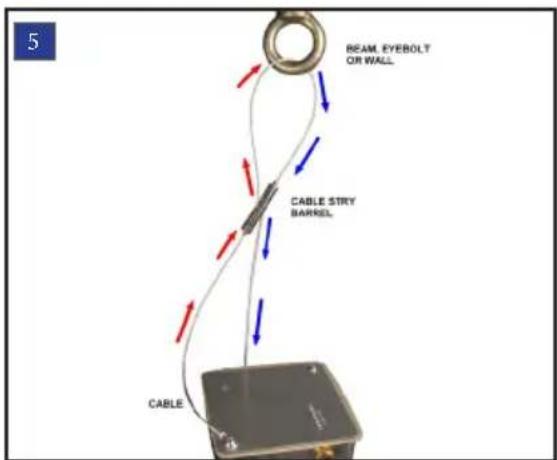
Wrap the cable around a beam, eyebolt or hanger. Then slip the cable through the top of cable stay barrel pulling excess cable until taut.
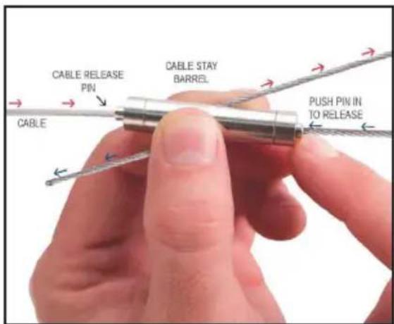
To release cable, depress the cable release pin on either end to release the loop or to extend cable length.
Brand : Audix
Model : M3WHM
Category : Microphone