
HVWCIP-R - AV Screen AG Neovo - Free user manual and instructions
Find the device manual for free HVWCIP-R AG Neovo in PDF.


| Product Type | HDMI Receiver (H.264/MPEG-4 AVC) |
| Input Interface | 1 x CAT5/6 (RJ-45) |
| Output Interface | 1 x HDMI 1.3, 1 x Stereo Audio (Phoenix connector) |
| Maximum Resolution | 1920 x 1200 @ 60Hz |
| Video Compression | H.264/MPEG-4 AVC (Baseline, Main, High Profile) |
| End-to-End Latency | Low latency: 60-90ms; High quality: 250-300ms |
| Power Supply | 12V DC 1A (PoE Class 0, up to 15.4W) |
| Power Consumption | 6W (max) |
| Dimensions (L x H x D) | 267 x 25 x 112 mm (10.5 x 1.0 x 4.4 in) |
| Weight | 0.6 kg (1.3 lbs) |
| ESD Protection | ±8kV (air-gap), ±4kV (contact) |
| Operating Temperature | 0°C to 40°C (32°F to 104°F) |
| Storage Temperature | -20°C to 60°C (-4°F to 140°F) |
| Relative Humidity | 20% to 90% RH (non-condensing) |
| Control Methods | PC Configurator, Web GUI, iPad App, RS-232, Telnet |
| RS-232 | Data pass-through for bidirectional control |
| Audio De-embedding | Yes, via stereo Phoenix connector |
| PoE Support | Yes, Class 0 (up to 15.4W) |
| IP Features | Auto IP, Zeroconf, IGMP v2/v3, TCP/IP, UDP |
| HDCP Compliance | Yes, HDCP compliant |
| Package Contents | 1x HVWCIP-R, 1x Power Adapter, 2x Phoenix Connectors, 1x User Manual |
Frequently Asked Questions - HVWCIP-R AG Neovo
User questions about HVWCIP-R AG Neovo
0 question about this device. Answer the ones you know or ask your own.
Ask a new question about this device
Download the instructions for your AV Screen in PDF format for free! Find your manual HVWCIP-R - AG Neovo and take your electronic device back in hand. On this page are published all the documents necessary for the use of your device. HVWCIP-R by AG Neovo.
USER MANUAL HVWCIP-R AG Neovo
Chapter 1: GETTING STARTED ....2
1.1 IMPORTANT SAFE GUARDS....2
1.2 SAFETY INSTRUCTIONS....2
1.3 REGULATORY NOTICES FEDERAL COMMUNICATIONS COMMISSION (FCC)....3
Chapter 2: INTRODUCTION....4
2.1 PACKAGE CONTENTS....5
2.2 BEFORE INSTALLATION....5
2.3 APPLICATION DIAGRAM 6
2.4 PANEL DESCRIPTION 7
2.4.1 FRONT PANEL (Transmitter, HVWCIP-T)....7
2.4.2 REAR PANEL (Transmitter, HVWCIP-T)....7
2.4.3 FRONT PANEL (Receiver, HVWCIP-R) 8
2.4.4 REAR PANEL (Receiver, HVWCIP-R) 8
Chapter 3: INSTALLATION (HVWCIP-SET) POINT to POINT....9
3.1 APPLICATION....9
3.1.1 IP Matrix Switch Guide 9
3.2 NETWORKING GUIDE 10
3.2.1 SIMPLE SETUP GUIDE FOR NETWORK SWITCH.... 10
3.2.2 POE REQUIREMENTS 10
Chapter 4: PC CONFIGURATOR....11
4.1 SETTING A STATIC IP ON YOUR COMPUTER.... 11
Chapter 5: SPECIFICATIONS....14
Chapter 6: TROUBLESHOOTING....17
GETTING STARTED
1.1 IMPORTANT SAFE GUARDS
Please read all of these instructions carefully before you use the device. Save this manual for future reference.
What the warranty does not cover
- Any product, on which the serial number has been defaced, modified or removed.
- Damage, deterioration or malfunction resulting from:
- Accident, misuse, neglect, fire, water, lightning, or other acts of nature, unauthorized product modification, or failure to follow instructions supplied with the product.
- Repair or attempted repair by anyone not authorized by us.
- Any damage of the product due to shipment.
- Removal or installation of the product.
- External causes to the product, such as electric power fluctuation or failure.
- Use of supplies or parts not meeting our specifications.
• Normal wear and tear. - Any other causes which does not relate to a product defect.
- Removal, installation, and set-up service charges.
1.2 SAFETY INSTRUCTIONS
The HVWCIP-SET, HDMI H.264 IP Matrix Transmitter/Receiver has been tested for conformance to safety regulations and requirements, and has been certified for international use. However, like all electronic equipments, the HVWCIP-SET should be used with care. Read the following safety instructions to protect yourself from possible injury and to minimize the risk of damage to the unit.
Do not dismantle the housing or modify the module.
⚠ Dismantling the housing or modifying the module may result in electrical shock or burn.
⚠️ Refer all servicing to qualified service personnel.
Do not attempt to service this product yourself as opening or removing housing may expose you to dangerous voltage or other hazards
⚠️ Keep the module away from liquids.
Spillage into the housing may result in fire, electrical shock, or equipment damage. If an object or liquid falls or spills on to the housing, unplug the module immediately.
Have the module checked by a qualified service engineer before using it again.
Do not use liquid or aerosol cleaners to clean this unit. Always unplug the power to the device before cleaning.
GETTING STARTED
1.3 REGULATORY NOTICES FEDERAL COMMUNICATIONS COMMISSION (FCC)
This equipment has been tested and found to comply with Part 15 of the FCC rules. These limits are designed to provide reasonable protection against harmful interference in a residential installation. Any changes or modifications made to this equipment may void the user's authority to operate this equipment.
| Warning Symbol Description | |
 | ONLY USE THE PROVIDED POWER CABLE OR POWER ADAPTER SUPPLIED. DO NOT TAMPER WITH THE ELECTRICAL PARTS. THIS MAY RESULT IN ELECTRICAL SHOCK OR BURN. |
 | DO NOT TAMPER WITH THE UNIT. DOING SO WILL VOID THE WARRANTY AND CONTINUED USE OF THE PRODUCT. |
 | THE VIDEO BOARDS ARE VERY SENSITIVE TO STATIC. PLEASE ENSURE IF RACK MOUNTED OR INSTALLED ON A SURFACE, IT SHOULD BE IN A GROUNDED ENVIROMENT. |

natural_image
Blue circular icon with a white human figure holding an open book (no text or symbols)WARNING
Read & understand user guide before using this device.
Failure to follow the proper installation instructions could result in damage to the product and preventing expected results.
INTRODUCTION
The HVWCIP-SET, HDMI H.264 IP Videowall/Matrix Receiver/Transmitter delivers end-to-end streaming media over IP networks. The HVWCIP-SET is composed of two units a HVWCIP-R and an HVWCIP-T. The HVWCIP-R H.264/ MPEG-4 AVC video compression format, it receives the encoded IP signal through LAN port and decodes video/audio signal out through HDMI interface, it also supports stereo de-embedding and streaming resolutions up to 1920 x 1200@60Hz.
FEATURES:
- Flexible PC,WEB GUI iPad control;
• CEC Function on the Receiver;
• Supports live IP video stream decoding 480p@60Hz to 1920 x 1200@60Hz; - Supports POE;
- Allows video previewing via iPad App and Windows 7 software 352x288@5Hz;
• Supports multiple interfaces HDMI, DVI signals over IP networks; - Supports audio embedding and de-embedding;
• Built in-auto scaler;
• Supports H.264 features baseline profile, main profile and high profile;
• Supports H.264, TCP/IP, Telnet, UDP and IGMP; - Support Telnet, WEB GUI control and 3rd Party control sytems API commands;
- Supports Auto IP, Zero-configuration networking (zeroconf)
- Seamless switching, no black screen, no frame lock.
- Configurable encoding bit rate up to 30 Mbps
• Auto input format detection - HDCP compliant
Other features include:
Point to Point - (Direct Connection with CAT5/6) - 100m (330ft)
Point to Multi - point with CAT5/6 requires a POE Network Switch which supports port based, IGMP v2.0 or above protocol.
Videowall and Matrix Function – with CAT 5/6 cable without any signal loss add multiple Sources to multiple transmitters which links via LAN by cascading any POE Gigabit Ethernet switches up to 3 levels, to the receivers connected to the HD Monitors at different locations on the Network. Transporting full HD 1080p video and internally H.264 video compression adapts to available network bandwidth if needed while retaining vivid picture with PCM audio.
2.1 PACKAGE CONTENTS
Before you start the installation of the HDMI Extender, please check the package contents.
| 1 | HVWCIP-Series x 2(HVWCIP-T)(HVWCIP-R) |   |
| 2 | Power Adapter (+12V DC 1A) + International Adapters X 2 |  |
| 3 | Right and Left Ear Rack Sets X 1 | 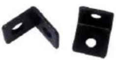 |
| 4 | Phoenix Connector (Male, 3.5mm, 3 pins) X 4Transmitter X 2Receiver X 2 |  |
| 5 | USER'S MANUAL X 1 |  |
2.2 BEFORE INSTALLATION
- Put the product in a level and stable location. If the product falls, it may cause damage or malfunction to components within the casing.
- Do not place the product in temperatures under 0°C or over 50°C. High humidity may also cause the unit to malfunction.
- Use the DC power adapter with correct specifications supplied with the unit. If the improper power supply is used, this may result in malfunction of the unit and may cause fire.
- Do not twist or pull by force the ends of the UTP cable. It will cause malfunction.
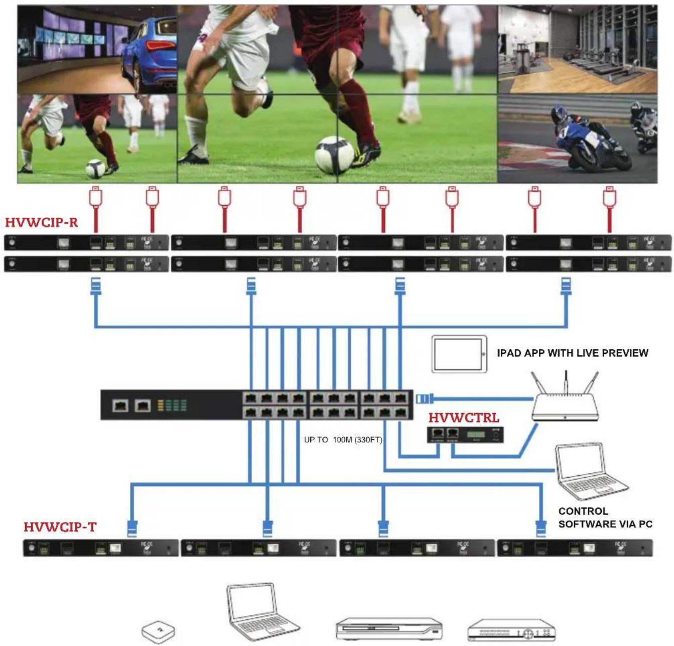
2.3 APPLICATION DIAGRAM
HVWCIP-SET
CABLE INDEX
Input / Output
CAT-5e / CAT-6
AUDIO
MULTI SOURCE TO MULTI DISPLAY
1080p60 = 100m (328 feet) CAT6
WUXGA = 100m (328 feet) CAT6
flowchart
graph TD
    subgraph TopPanel
        A["客户端"] --> B["IPAD APP WITH LIVE PREVIEW"]
        B --> C["IPAD APP"]
        C --> D["IPAD APP"]
        D --> E["IPAD APP"]
        E --> F["IPAD APP"]
        F --> G["IPAD APP"]
        G --> H["IPAD APP"]
        H --> I["IPAD APP"]
        I --> J["IPAD APP"]
        J --> K["IPAD APP"]
        K --> L["IPAD APP"]
        L --> M["IPAD APP"]
        M --> N["IPAD APP"]
        N --> O["IPAD APP"]
        O --> P["IPAD APP"]
        P --> Q["IPAD APP"]
        Q --> R["IPAD APP"]
        R --> S["IPAD APP"]
        S --> T["IPAD APP"]
        T --> U["IPAD APP"]
        U --> V["IPAD APP"]
        V --> W["IPAD APP"]
        W --> X["IPAD APP"]
        X --> Y["IPAD APP"]
        Y --> Z["IPAD APP"]
        Z --> AA["IPAD APP"]
        AA --> AB["IPAD APP"]
        AB --> AC["IPAD APP"]
        AC --> AD["IPAD APP"]
        AD --> AE["IPAD APP"]
        AE --> AF["IPAD APP"]
        AF --> AG["IPAD APP"]
        AG --> AH["IPAD APP"]
        AH --> AI["IPAD APP"]
        AI --> AJ["IPAD APP"]
        AJ --> AK["IPAD APP"]
        AK --> AL["IPAD APP"]
        AL --> AM["IPAD APP"]
        AM --> AN["IPAD APP"]
        AN --> AO["IPAD APP"]
        AO --> AP["IPAD APP"]
        AP --> AQ["IPAD APP"]
        AQ --> AR["IPAD APP"]
        AR --> AS["IPAD APP"]
        AS --> AT["IPAD APP"]
        AT --> AU["IPAD APP"]
        AU --> AV["IPAD APP"]
        AV --> AW["IPAD APP"]
        AW --> AX["IPAD APP"]
        AX --> AY["IPAD APP"]
        AY --> AZ["IPAD APP"]
        AZ --> BA["IPAD APP"]
        BA --> BB["IPAD APP"]
        BB --> BC["IPAD APP"]
        BC --> BD["IPAD APP"]
        BD --> BE["IPAD APP"]
        BE --> BF["IPAD APP"]
        BF --> BG["IPAD APP"]
        BG --> BH["IPAD APP"]
        BH --> BI["IPAD APP"]
        BI --> BJ["IPAD APP"]
        BJ --> BK["IPAD APP"]
        BK --> BL["IPAD APP"]
        BL --> BM["IPAD APP"]
        BM --> BN["IPAD APP"]
        BN --> BO["IPAD APP"]
        BO --> BP["IPAD APP"]
        BP --> BQ["IPAD APP"]
        BQ --> BR["IPAD APP"]
        BR --> BS["IPAD APP"]
        BS --> BT["IPAD APP"]
        BT --> BU["IPAD APP"]
        BU --> BV["IPAD APP"]
        BV --> BW["IPAD APP"]
        BW --> BX["IPAD APP"]
        BX --> BY["IPAD APP"]
        BY --> BZ["IPAD APP"]
        BZ --> CA["IPAD APP"]
        CA --> CB["IPAD APP"]
        CB --> CC["IPAD APP"]
        CC --> CD["IPAD APP"]
        CD --> CE["IPAD APP"]
        CE --> CF["IPAD APP"]
        CF --> CG["IPAD APP"]
        CG --> CH["IPAD APP"]
        CH --> CI["IPAD APP"]
        CI --> CJ["IPAD APP"]
        CJ --> CK["IPAD APP"]
        CK --> CR["IPAD APP"]
        CR --> CS["IPAD APP"]
        CS --> CT["IPAD APP"]
        CT --> CU["IPAD APP"]
        CU --> CV["IPAD APP"]
        CV --> CW["IPAD APP"]
        CW --> CX["IPAD APP"]
        CX --> CY["IPAD APP"]
        CY --> CZ["IPAD APP"]
        CZ --> DA["IPAD APP"]
        DA --> DB["IPAD APP"]
        DB --> DC["IPAD APP"]
        DC --> DD["IPAD APP"]
        DD --> DE["IPAD APP"]
        DE --> DF["IPAD APP"]
        DF --> DG["IPAD APP"]
        DG --> DH["IPAD APP"]
        DH --> DI["IPAD APP"]
        DI --> DJ["IPAD APP"]
        DJ --> DK["IPAD APP"]
        DK --> DL["IPAD APP"]
        DL --> DV["IPAD APP"]
        DV --> DW["IPAD APP"]
        DW --> DX["IPAD APP"]
        DX --> DXB["IPAD APP"]
DVI/HDMI SOURCE VGA SOURCE YPbPr SOURCE CVBS SOURCE
2.4 PANEL DESCRIPTION
2.4.1 FRONT PANEL (Transmitter, HVWCIP-T)

| 1 Power LED: Indicates if the unit is powered OFF or ON by a RED LED |
| 2 Status LED: Steady Blue Light ON indicates unit is communicating properly. LED blinking waiting on Source |
2.4.2 REAR PANEL (Transmitter, HVWCIP-T)

| 3 | Power Jack: DC 12V 1A 4 RS 232: RS-232 Data | pass-through port for receiving /sending commands to RS 232 devices. |
| 5 | HDMI IN: Connect to HDMI/DVI Source. 6 Stereo | Audio OUT: Connects to an audio output device such as an amplifier for audio de-embedding. |
| 7 | CAT5/6: Used for transporting video/audio streams to Receiver units connected. | Ground Screw: Ground connection prevent device from voltage damage. |
2.4.3 FRONT PANEL (Receiver, HVWCIP-R)
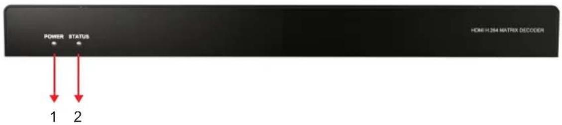
| 1 Power LED: Indicates if the unit is powered OFF or ON by a RED LED. |
| 2 $status LED: Steady Blue Light ON indicates unit is communicating properly. LED blinking waiting on Transmitter. |
2.4.4 REAR PANEL (Receiver, HVWCIP-R)

| 3 | Power: 12V 1A DC Power Jack. 4 CAT 5/6: used | for accepting video/ audio streams from the Transmitter units connected. |
| 5 | HDMI OUT: Connect to HDMI Display. 6 Stereo | Audio OUT: Connects to an audio output device such as an amplifier for audio de-embedding. |
| 7 | RS 232 : RS-232 Data pass-through port for receiving / sending commands to RS 232 devices. | 8 Ground Screw: Ground connection prevent device from voltage damage. |
INSTALLATION
INSTALLATION (HVWCIP-Set) POINT to POINT
To setup HVWCIP-SET please follow these steps for connecting to a device:
- Turn off all devices including monitors / TV.
- Connect an HDMI source (such as a Blu-Ray Disc player or PC) to the Transmitter HVWCIP-T.
- Connect CAT5/6 from Transmitter to Receiver at the CAT5/6 port.
- Connect an HDMI out from HVWCIP-R receiver to a Display/Monitor.
- Connect Audio out to Speakers or Amplifier.
- Ensure all cable connections are secure and not loose.
- Plug in 12V DC power (supplied) and connect the HVWCIP-T and HVWCIP-R to power jack.
- Power on HDMI Source.
- Power on the HDMI display.
NOTE: For network setup please see the Network switch configuration guide and Network Connection guide to achieve best results.
3.1 APPLICATION
3.1.1 IP Matrix Switch Guide
| Transmitter and Receiver Guide Networking Switch Guide | |||
| Distribution Status | Total Quantity | Network Topology | Recommended Switches |
| Centralized | Less than or equal to 20 Transmitter / Receiver | Single Switch Networking | Cisco SG 300 24-port 1000 Mbps Ethernet Switch HUAWEI 24-port 1000 Mbps Ethernet Switch |
| Less than or equal to 40 Transmitter / Receiver | Cisco SG300 /500 48-port 1000 Mbps Ethernet Switch HUAWEI 48-port 1000 Mbps Ethernet Switch | ||
| More than 40 Transmitter / Receiver | Cascading Switch Networking | Cisco switch SG Series or Catalyst: Core switches uses 1000 Mbps Ethernet switches. Extended switches use 1000 Mbps Ethernet switches | |
| Distributed No requirement | |||
INSTALLATION
3.2 NETWORKING GUIDE
HVWCIP-R HDMI over IP units can be networked together with a recommended Layer 2 Gigabit Smart Switches. As mentioned previously in section 3 the importance of calculation for the capacity of the switch meets the requirements of the number of Transmitters/Receivers you have on your network. These units can perform well over a standard network infrastructure, however the quality of this infrastructure is critical. We have tested many brands of switches all of which perform well in small system configurations of around 10 Transmitters and Receivers.
3.2.1 Simple Setup Guide for Network switch
HVWCIP-R should be connected to a Layer 2 managed switch which supports Multicast & IGMP snooping.
Do not connect any units to the switch until all the network switch configuration has been. For recommended switches and PDF configuration guides please see the download section of HVWCIP-Series at agneovo.com
3.2.2 POE Requirements
It is not necessary to change the IP addresses of the transmitters and receivers units – factory default Auto IP is used to configure correct IP addresses to simply plug and play.
DHCP addresses are not recommended, while Static addresses are for supervised setups and network strict environments.
Failure to note the IP settings of any unit changed may result in a complicated reset procedure.
Most HVWCIP-R installations use the POE (Power Over Ethernet) function to power the transmitters and receivers units.
HVWCIP-SET is Class 0 rated POE devices, they can require up to 15.4W of power each, but tested their actual power draw is between 5-7W. In order to calculate the number of devices that is recommended on a network switch please divide the total POE power capacity of the switch by 15.4. Please see the example:
CISCO SG300-52P with a POE power output of 375W: 375 / 15.4 = 24.35. From the answer 24 devices can be powered by this switch. In order to have all ports powered by POE on a network switch, please see the example:
SG300-52MP which provides 740W. 740 / 15.4 = 48. From the answer 48 devices can be powered by this switch.
PC CONFIGURATOR
You can connect multiple HVWCIP-T and the HVWCIP-R H.264 receiver to build a modular IP matrix. With the PC configurator, you can configure and manage this function. For more information, see the user guide of PC configurator.
Minimum System Requirements PC Software
Operating System: Microsoft® Windows® XP, Windows® Vista, Windows® 7, Windows® 8 or Windows® 10
CPU: 1.5 GHz
Memory: 1 GB of RAM
HDD: 32 GB of available hard disk space
Network: 10/100 NIC
4.1 SETTING A STATIC IP ON YOUR COMPUTER
Before using the AG Neovo PC Configurator, please ensure you download the most recent version from the product HVWCIP-T Transmitter and HVWCIP-R Receiver website link /downloads PC control software.
All devices must be are in the same network segment. To verify and properly control the devices, please set a static IP on your computer. See the instructions below if not sure on how to proceed:
The Transmitter and Receiver units are pre-configured with AutoIP. Upon connecting the units to a stand alone network switch (without router attached), the units will be on IP address range at 169.254.1.1 and subnet mask 255.255.0.0.
Set your computer's IP address as 169.254.X.X and subnet mask as 255.255.0.0.
A Windows 7 PC/Laptop is used as an example to configure a static IP address.
-
Click Start.
-
Choose Control Panel > Network and Internet > Network and Sharing Center > Change
Adapter Settings, right click Local Area Connection, and then choose Properties.

PC CONFIGURATOR
- Double-click Internet Protocol Version 4 (TCP/IPv4).

- Select Use the following IP address. After configuring the settings in the following example, click OK.
• IP address: 169.254.2.5
- Subnet mask: 255.255.0.0

- Click OK.
PC CONFIGURATOR
CONFIGURING YOUR OPERATING SYSTEM
Firewall
Your operating system firewall may block some features of PC Configurator and prevent it from communicating with Transmitter and Receiver. A computer running Windows 7 is used as an example to configure your operating system firewall through either of the following two approaches.
Method 1
You can configure the firewall in the Windows Firewall panel on your computer, for example select both Home/Work (Private) and Public for PC Configurator & Matrix.

Method 2
You can also configure the firewall in the Windows Security Alert window. When starting MaintainTool, the Windows Security Alert may display. If so, use the administrator privileges to select a network you allow this software to communicate on, for example select both private and public networks, and then click Allow access.

SPECIFICATIONS
| ITEM DESCRIPTION | ||
| UNITS HVWCIP-T HVW | VCIP-R | |
| UNIT DESCRIPTION H | DMI Transmitter HDMI Receiver | |
| Input Video Port 1 x HD | MI IN 1 x CAT5/6 | |
| Input Video Type HDMI, | DVI 1.0 H.264/MPEG-4 AVC | |
| Input Resolution | HDMI:640 x 480@60Hz,480i@60Hz 480p@60Hz,576i@50Hz,576P@50Hz,800 x 600@60Hz,1024 x 768@60Hz,720p@50Hz,720p@60Hz,1280 x 800@60Hz,1280 x 1024@60Hz,1360 x 768@60Hz,1366 x 768@60Hz,1400 x 1050@60Hz,1440 x 900@60Hz,1680 x 1050@60Hz,1080i@50Hz, 1080i@60Hz,1080p@24Hz, 1080p@25Hz, 1080p@30Hz,1080p@50Hz,1080p@60Hz,1920 x 1200@60HzDVI:640 x 480@60Hz,480i@60Hz, 480p@60Hz,576i@50Hz, 576P@50Hz,800 x 600@60Hz,1024 x 768@60Hz,720p@50Hz, 720p@60Hz,1280 x 800@60Hz, 1280 x1024@60Hz,1360 x 768@60Hz, 1366 x 768@60Hz,1400 x 1050@60Hz, 1440 x 900@60Hz,1680 x 1050@60Hz,1080i@50Hz, 1080@60Hz,1080p@24Hz, 1080p@25Hz, 1080p@30Hz,1080p@50Hz, 1080p@60Hz,1920 x 1200@60Hz | 480p@60Hz~1920x1200@60Hz |
SPECIFICATIONS
| ITEM DESCRIPTION | ||
| Input Resolution | VGA:640 x 480@60Hz,800 x 600@60Hz1024 x 768@60Hz,1280 x 1024@60Hz1280 x 720@60Hz,1280 x 768@60Hz,1280 x 800@60Hz,1360 x 768@60Hz, 1366 x 768@60Hz,1440 x 900@60Hz1400 x 1050@60Hz1680 x 1050@60Hz,1920 x 1080@60Hz,1920 x 1200@60HzYPbPr:720 x 480i@60Hz, 720 x 480p@60Hz,720 x 576i@50Hz, 720 x 576P@50Hz,1280 x720p@50Hz, 1280x720p@60Hz1920 x1080i@50Hz, 1920 x 1080i@60HzCVBS:480i@60Hz,576i@50Hz | |
| Input Video Signal 0.5~ | 1.2 V p-p NA | |
| Encoding Data Rate Up | to 30 Mbps, configurable NA | |
| Output Video Ports 1 x | CAT5/6 1 x HDMI | |
| Output Video Type H.26 | 4/MPEG-4 AVC HDMI 1.3 | |
| Output Video Resolutions | Large IP stream:480p@60Hz~1920 x 1200@60HzSmall IP stream: 352x288@5Hz | HDMI:480p@60Hz,576p@50Hz,800 x600@60Hz,1024 x768@60Hz,720p@50Hz, 720p@60Hz, 1280 x800@60Hz,1280x1024@60Hz,1366 x768@60Hz,1440x900@60Hz,1600 x1200@60Hz,1680 x 1050@60Hz,1080p@24Hz,1080p@25Hz,1080p@30Hz,1080p@50Hz, 1080p@60Hz,1920 x 1200@60Hz |
| Video Impedence 100 Ω | 100 Ω | |
| Input DDC Signal 5 V p-p (TTL) NA | ||
SPECIFICATIONS
ITEM DESCRIPTION
| End-to-End Time Latency | About 60ms-90ms (Low latency mode) About 250ms-300ms (High quality mode) | About 60ms-90ms (Low latency mode) About 250ms-300ms (High quality mode |
| Input Audio Ports 1 x Audio jack 1 x CAT5/6 | ||
| Input Audio Format Stereo | Audio embedded in streaming media input | |
| Output Audio Ports 1 x Phoenix connector 1 x Phoenix connector | ||
| Output Audio Format Stereo | ||
| Control Method | Rear panel CAT5/6 port, PC configurator and RS-232 | PC configurator and RS-232 |
| Power Supply 12 V 1 A DC 12 V 1 A DC | ||
| Power Consumption 6W (Max.) 6W (Max.) | ||
| Shipping Dimensions (L X H X D) | 310 x 76 x 180 mm (12.2" x 3.0" x7.1") | 310 x 180 x 76 mm (12.2" x 7.1" x 3.0") |
| Product Dimensions (L X H X D) | 236 x 25 x 94 mm (9.3" x 1.0" x 3.7") | 267 x 25 x 112 mm (10.5" x 1.0" x 4.4") |
| Weight | 0.5 kg (1.0 lbs) | 0.6 kg (1.3 lbs) |
| ESD Protection | Human body model: -±8kV (air-gap discharge) -±4kV (contact discharge) | Human body model: -±8kV (air-gap discharge) -±4kV (contact discharge) |
Environmental
| OPERATING TEMPERATURE | 32° ~ 104°F (0° to 40°C) | 32° ~ 104°F (0° to 40°C) |
| STORAGE TEMPERATURE | -4° ~ 140°F (-20° ~ 60°C) | -4° ~ 140°F (-20° ~ 60°C) |
| RELATIVE HUMIDITY | 20~90% RH (no condensation) | 20~90% RH (no condensation) |
TROUBLESHOOTING
PROBLEM POSSIBLE SOLUTION
| PC Configurator cannot find devices | 1.Check the Windows Firewall.Taking Windows 7 as an example: Click Start menu, go to Control Panel>System and Security >Windows Firewall > Allowed Programs, select Home/Work (Private) and Public for PC configurator.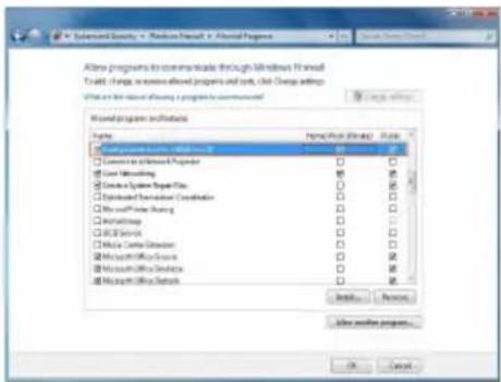 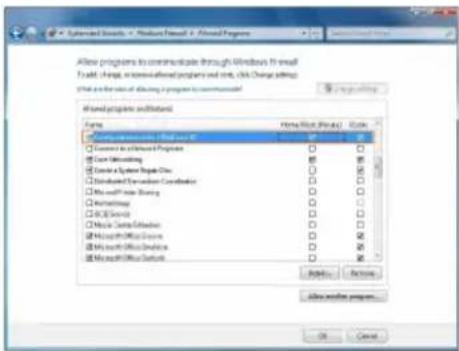 PC Configurator (HDMI over IP) Maintain Tool2.Check the IP address and subnet mask of your computer.The computer, Transmitter, Receiver and switch should be in the same network segment. Therefore, set your computer's IP address as 169.254.X.X and subnet mask as 255.255.0.0.For more information, see the description in the networking guide.3.Check the switch configuration, and that IGMP snooping and all the other functions are enabled. PC Configurator (HDMI over IP) Maintain Tool2.Check the IP address and subnet mask of your computer.The computer, Transmitter, Receiver and switch should be in the same network segment. Therefore, set your computer's IP address as 169.254.X.X and subnet mask as 255.255.0.0.For more information, see the description in the networking guide.3.Check the switch configuration, and that IGMP snooping and all the other functions are enabled. | |
| Display Showing No Picture | 1. Check all devices are powered on.2. Check all cables are securely seated and connected properly.3. Check the LED STATUS indicators on the Receivers to see if Transmitters and Receivers are linked correctly. Blue Steady=OK Blue Blinking=standby To link the devices use the PC configurator on your PC/Laptop, drag the Transmitter to the Receiver and click apply.4. Check that source device is powered on and the HDMI cable is connected. Check the displays are powered on and the correct input selection. Check the HDMI cable is plugged into the correct port. | |
TROUBLESHOOTING
PROBLEM POSSIBLE SOLUTION
| Display Showing No Picture | 5. Example switch to HDMI 1 if a display's HDMI 1 port is connected to Receiver via an HDMI cable.6. Ensure the displays/monitor support HDCP.7. Check native EDID timings from the manufactures guide to match the Receiver output resolution. If so, replace the displays with other models.8. Check that Transmitter supports the resolutions of the input signals. For more information about the resolutions, see “Specifications” of “Introduction” section.9. Check the switch configuration, and that IGMP snooping and all the other functions are enabled. |
| No audio | 1. Check all the devices are powered on.2. Check all cables are securely seated and connected properly.3. Check the LED STATUS indicators on the Receivers to see if Transmitters and Receivers are linked correctly. Blue Steady=OK Blue Blinking=standby To link the devices use the PC configurator on your PC/Laptop, drag the Transmitter to the Receiver and click apply.4. Check the A/V device is playing a video with sound.5. Check the A/V devices audio output with an RCA jack to a speaker or amplifier, also use a headphones if the equipment has a 3.5mm audio out.6. Check the A/V devices are not set to mute or 0 for volume.7. Check Receiver is not set to mute, open PC configurator and right click on the Receiver and on the drop down select mute . For more information, see the user guide of PC configurator. |
| No Live preview on Windows7 or iPad App | 1. Please ensure your HVWCIP-T, HVWCTRL and your wireless router is on the same network segment.2. For Window 7/iPad app, please ensure the units are VersionHVWCIP-T V2.8.3HVWCIP-R V2.8.2HVWCTRL V1.5/V5.10 (5.11)CTRLPRO-M V7.0  |
TROUBLESHOOTING
-
All HDMI over CATx transmission distances are measured using Belden CAT6A (625MHz), 4-Pair, UTP-Unshielded, Riser-CMR, Premise Horizontal Cable, 23 AWG Solid Bare Copper Conductors, Polyolefin Insulation, Patented Double-H spline, Ripcord, PVC Jacket using Quantum 980 signal HDMI Video Generator Module with Video Pattern Testing and shielded ends.
-
The transmission length is largely affected by the type of category cables, also the type of HDMI sources, and the type of HDMI display. The testing result shows solid UTP cables (usually in the form of 300m or 1000ft bulk cable) can transmit a lot longer signals than stranded UTP cables (usually in the form of patch cords). Shielded STP connectors are better suit than unshielded UTP connectors. A solid UTP CAT6A cable shows longer transmission length than solid UTP CAT5E/6E cable.
-
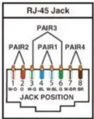
EIA/TIA-568-B termination (T568B) for category cables is recommended.
-
To reduce the interference among the unshielded twisted pairs of wires in category cable, you can use shielded STP cables with shielded connector to improve EMI problems, which occurs in poor wiring environments with unplanned cable runs situated away from EMI interference.
-
Because the quality of the category cables has the major effects in how long transmission distance will be made and how good is the received signal on the display, the actual transmission length is subject to high quality category cables. For resolution greater than 1080i or 1280x1024, a solid CAT6E 250MHz cable is the only viable choice.
| Data Link TIA/EIA-568-B | |||
| PIN | Color | Function | |
| 1 |  | W-O | TX0- |
| 2 |  | O | TX0+ |
| 3 |  | W-G | TX1- |
| 4 |  | BL | TX2- |
| 5 |  | W-BL | TX2+ |
| 6 |  | G | TX1+ |
| 7 |  | W-BR | TXC- |
| 8 |  | BR | TXC+ |
PERFORMANCE GUIDE FOR HDMI OVER CATEGORY CABLE TRANSMISSION
| PERFORMANCE RATING TYPE OF CATEGORY CABLE | ||||
| WIRING SHIELDING CAT5 CAT5E CAT6 | ||||
| SOLID | UNSHIELDED (UTP) | ★★★ ★★★★ ★★★★★★ | ||
| SHIELDED (STP) | ★★★ ★★★ ★★★★ | |||
| STRANDED | UNSHIELDED (UTP) | ★ ★★ ★★ | ||
| SHIELDED (STP) | ★ ★ ★★ | |||
| TERMINATION | PLEASE USE EIA/TIA-568-B TERMINATION (T568B) AT ANY TIME | |||
- Chapter 1: GETTING STARTED ....2
- Chapter 2: INTRODUCTION....4
- Chapter 3: INSTALLATION (HVWCIP-SET) POINT to POINT....9
- Chapter 4: PC CONFIGURATOR....11
- Chapter 5: SPECIFICATIONS....14
- Chapter 6: TROUBLESHOOTING....17
- GETTING STARTED
- IMPORTANT SAFE GUARDS
- SAFETY INSTRUCTIONS
- REGULATORY NOTICES FEDERAL COMMUNICATIONS COMMISSION (FCC)
- WARNING
- INTRODUCTION
- FEATURES:
- PACKAGE CONTENTS
- BEFORE INSTALLATION
- APPLICATION DIAGRAM
- HVWCIP-SET
- PANEL DESCRIPTION
- FRONT PANEL (Transmitter, HVWCIP-T)
- REAR PANEL (Transmitter, HVWCIP-T)
- FRONT PANEL (Receiver, HVWCIP-R)
- REAR PANEL (Receiver, HVWCIP-R)
- INSTALLATION
- INSTALLATION (HVWCIP-Set) POINT to POINT
- APPLICATION
- IP Matrix Switch Guide
- NETWORKING GUIDE
- Simple Setup Guide for Network switch
- POE Requirements
- PC CONFIGURATOR
- SETTING A STATIC IP ON YOUR COMPUTER
- CONFIGURING YOUR OPERATING SYSTEM
- Firewall
- Method 1
- Method 2
- SPECIFICATIONS
- TROUBLESHOOTING
Brand : AG Neovo
Model : HVWCIP-R
Category : AV Screen