
SU-C700EB - Amplifier TECHNICS - Free user manual and instructions
Find the device manual for free SU-C700EB TECHNICS in PDF.


| Product Type | Stereo Integrated Amplifier |
| Brand | Technics |
| Model | SU-C700EB |
| Amplifier Technology | Full-digital amplifier with high-precision jitter reduction and PWM conversion circuit |
| Output Power (8 Ω) | 45 W + 45 W (1 kHz, 0.3% THD, 20 kHz LPF) |
| Output Power (4 Ω) | 70 W + 70 W (1 kHz, 0.5% THD, 20 kHz LPF) |
| Load Impedance | 4 Ω to 16 Ω |
| Frequency Response (LINE) | 20 Hz to 80 kHz (-3 dB, 8 Ω) |
| Frequency Response (PHONO) | 20 Hz to 20 kHz (RIAA deviation ±1 dB, 8 Ω) |
| Input Sensitivity (LINE) | 200 mV / 22 kΩ |
| Input Sensitivity (PHONO MM) | 2.5 mV / 47 kΩ |
| Digital Inputs | 3× Coaxial, 1× Optical, 1× USB (PC) |
| USB Audio Support | LPCM up to 192 kHz/32 bit, DSD64/128 (ASIO Native, DoP) |
| Headphone Output | 6.3 mm stereo jack |
| Power Consumption | 73 W (Standby: approx. 0.3 W) |
| Power Supply | AC 220-240 V, 50/60 Hz |
| Remote Control | Supplied (N2QAYA000096) |
| System Control Ports | CONTROL1/CONTROL2 (for linking with ST-C700/SL-C700) |
| Special Features | LAPC (Load Adaptive Phase Calibration), Low-noise linear power supply, Auto off function |
| Safety | Protection circuit against overheating; CE compliant |
Frequently Asked Questions - SU-C700EB TECHNICS
User questions about SU-C700EB TECHNICS
0 question about this device. Answer the ones you know or ask your own.
Ask a new question about this device
Download the instructions for your Amplifier in PDF format for free! Find your manual SU-C700EB - TECHNICS and take your electronic device back in hand. On this page are published all the documents necessary for the use of your device. SU-C700EB by TECHNICS.
USER MANUAL SU-C700EB TECHNICS
Operating Instructions
Stereo Integrated Amplifier
SU-C700
Music is borderless and timeless,
touching people's hearts across cultures and generations.
Each day the discovery of a truly emotive experience
from an unencountered sound awaits.
Let us take you on your journey to rediscover music.
Rediscover Music™
Technics
Thank you for purchasing this product.
Please read these instructions carefully before using this product, and save this manual for future use.
For the United Kingdom and Ireland customers
Sales and Support Information
Customer Communications Centre
●For customers within the UK: 0333 222 8777
●For customers within Ireland: 01 447 5229
- Monday–Friday 9:00 am – 5:00 pm, (Excluding public holidays).
- For further support on your product, please visit our website: www.technics.com/uk/
■ Features of this unit
This unit offers the following features:
Full-digital amplifier with a high-precision jitter reduction circuit and PWM conversion circuit
This unit is a full-digital amplifier. Its specially-designed jitter reduction circuit and high-precision PWM conversion circuit eliminate distortion, noise, and jitter.
LAPC (Load Adaptive Phase Calibration)
Adaptive processing of speaker impedance flattens frequency amplitude and phase characteristics. The result is the reproduction of sound with rich spatial expression.
High-speed and lower noise linear power supply
The combination of a large-current Schottky-barrier diode, a rectifier circuit with a large storage capacitor, and a stabilized power supply circuit achieves remarkably superior power supply that is both low-noise and plentiful.
■ Recommended devices
We recommend using Technics devices (optional) for superior audio quality.
| Product name Model number | |
| Network Audio Player ST-C700 | |
| Compact Disc Player SL-C700 | |
| Speaker System SB-C700 |
Safety precautions
WARNING
Unit
• To reduce the risk of fire, electric shock or product damage,
- Do not expose this unit to rain, moisture, dripping or splashing.
- Do not place objects filled with liquids, such as vases, on this unit.
- Use only the recommended accessories.
- Do not remove covers.
- Do not repair this unit by yourself. Refer servicing to qualified service personnel.
- Do not let metal objects fall inside this unit.
- Do not place heavy items on this unit.
AC mains lead
• To reduce the risk of fire, electric shock or product damage,
- Ensure that the power supply voltage corresponds to the voltage printed on this unit.
- Insert the mains plug fully into the socket outlet.
- Do not pull, bend, or place heavy items on the lead.
- Do not handle the plug with wet hands.
- Hold onto the mains plug body when disconnecting the plug.
- Do not use a damaged mains plug or socket outlet.
• The mains plug is the disconnecting device.
Install this unit so that the mains plug can be unplugged from the socket outlet immediately.
CAUTION
Unit
- Do not place sources of naked flames, such as lighted candles, on this unit.
- This unit may receive radio interference caused by mobile telephones
during use. If such interference occurs, please increase separation between this unit and the mobile telephone.
• This unit is intended for use in moderate climates. - Do not put any objects on this unit. This unit becomes hot while it is on.
Placement
- Place this unit on an even surface.
• To reduce the risk of fire, electric shock or product damage, - Do not install or place this unit in a bookcase, built-in cabinet or in another confined space. Ensure this unit is well ventilated.
- Do not obstruct this unit's ventilation openings with newspapers, tablecloths, curtains, and similar items.
- Do not expose this unit to direct sunlight, high temperatures, high humidity, and excessive vibration.
- Do not lift or carry this unit by holding any of its knobs or levers. Doing so may cause this unit to fall, resulting in personal injury or malfunction of this unit.
Battery
- Danger of explosion if battery is incorrectly replaced. Replace only with the type recommended by the manufacturer.
- Mishandling of batteries can cause electrolyte leakage and may cause a fire.
- Remove the battery if you do not intend to use the remote control for a long period of time. Store in a cool, dark place.
- Do not heat or expose to flame.
- Do not leave the battery(ies) in a car exposed to direct sunlight for a long period of time with doors and windows closed.
- Do not take apart or short circuit.
- Do not recharge alkaline or manganese batteries.
- Do not use batteries if the covering has been peeled off.
- Do not mix old and new batteries or different types at the same time.
- When disposing of the batteries, please contact your local authorities or dealer and ask for the correct method of disposal.
Caution for AC Mains Lead
(For the AC mains plug of three pins)
For your safety, please read the following text carefully.
This appliance is supplied with a moulded three pin mains plug for your safety and convenience.
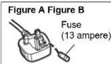
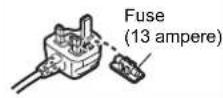
A 13-ampere fuse is fitted in this plug.
Should the fuse need to be replaced please ensure that the replacement fuse has a rating of 13-ampere and that it is approved by ASTA or BSI to BS1362. Check for the ASTA mark or the BSI mark on the body of the fuse.
If the plug contains a removable fuse cover you must ensure that it is refitted when the fuse is replaced.
If you lose the fuse cover the plug must not be used until a replacement cover is obtained.
A replacement fuse cover can be purchased from your local dealer.
Before use
Remove the connector cover.
How to replace the fuse
The location of the fuse differ according to the type of AC mains plug (figures A and B). Confirm the AC mains plug fitted and follow the instructions below. Illustrations may differ from actual AC mains plug.
- Open the fuse cover with a screwdriver.

- Replace the fuse and close or attach the fuse cover.
Disposal of Old Equipment and Batteries
Only for European Union and countries with recycling systems
These symbols on the products, packaging, and/or accompanying documents mean that used electrical and electronic products and batteries must not be mixed with general household waste.
For proper treatment, recovery and recycling of old products and used batteries, please take them to applicable collection points in accordance with your national legislation.
By disposing of them correctly, you will help to save valuable resources and prevent any potential negative effects on human health and the environment. For more information about collection and recycling, please contact your local municipality.
Penalties may be applicable for incorrect disposal of this waste, in accordance with national legislation.
Note for the battery symbol (bottom symbol):
This symbol might be used in combination with a chemical symbol. In this case it complies with the requirement set by the Directive for the chemical involved.


Table of contents
Safety precautions....5
Accessories....6
Unit care 6
Control reference guide ....7
Getting started 9
Operations.... 13
Listening to audio from a PC, etc.... 15
Troubleshooting....16
Specifications.... 17
About descriptions in these operating instructions
- Pages to be referred to are indicated as “⇒ ○○”.
●The illustrations shown may differ from your unit. - Unless otherwise indicated, operations are described using the remote control.
Accessories
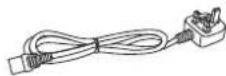
□ 1 AC mains lead
For the United Kingdom and Ireland
(K2CT2YY00103)
□ 1 Remote control (N2QAYA000096)

For Australia and New Zealand
(K2CJ2YY00097)

□ 2 Batteries for remote control

For South Africa
(K2CQ2YY00127)


- Product numbers provided in these operating instructions are correct as of November 2014. These may be subject to change.
- Do not use AC mains lead with other equipment.
■ Using the remote control
Insert the battery so the terminals (+ and -)
match those in the remote control.
Point it at the remote control signal sensor on this unit. ( 7)
- Keep the batteries out of reach of children to prevent swallowing.

Unit care
Pull out the AC mains lead from the outlet before maintenance. Clean this unit with a soft cloth.
- When dirt is heavy, wring a wet cloth tightly to wipe the dirt, and then wipe it with a soft cloth.
- Do not use solvents including benzine, thinner, alcohol, kitchen detergent, a chemical wiper, etc. This might cause the exterior case to be deformed or the coating to come off.
Control reference guide
This unit
Front

① Power switch lever
Turn on/off this unit.
- The remote control do not operate when the power switch lever is in the lowered position.
② Headphones jack
For connecting a headphone plug.
- When a plug is connected, the speakers do not output sound.
- Excessive sound pressure from earphones and headphones can cause hearing loss.
- Listening at full volume for long periods may damage the user's ears.
③ LAPC indicator ( 13)
The indicator lights up when amplifier output correction is on.
④ Volume knob
Adjust the volume.
- When this unit is muted, if you turn the knob anticlockwise until it stops and then turn it clockwise, the muting will be cancelled.
⑤ Remote control signal sensor
Distance: Within approx. 7 m directly in front Angle: Approx. 30° left and right
⑥ Input selector knob
Turn this knob clockwise or anticlockwise to switch the input source. ( 13)
⑦ Peak power meter
Display the output level.
⑧ Input indicator ( 13)
The indicator for the selected input source lights up.
- The indicator blinks if you select "PC", "COAX1", "COAX2", "COAX3" or "OPT" when the device is not connected to this unit.
■ Rear

⑨ PHONO EARTH terminal [PHONO EARTH] (⇒ 11)
For connecting the ground wire of a record player.
⑩ Analogue audio input terminal [PHONO] ( 11)
For connecting a record player.
• MM cartridges are supported.
⑪ Attenuator [ATTENUATOR]
If audio distortion occurs when using the analogue audio input terminal [LINE IN], set this switch to [ON].
⑫ Analogue audio input terminal [LINE IN] ( 11)
⑬ Speaker terminals [SPEAKERS] ( 9)
⑭ AC IN terminal [AC IN \~] (⇒ 12)
⑮ Digital audio input terminal [PC] ( 15) For connecting to a PC, etc.
⑯ Digital audio input terminal [OPT IN] (⇒ 11)
⑰ Digital audio input terminals [COAX1 IN]/[COAX2 IN]/[COAX3 IN] (⇒ 10, 11)
⑱ System terminals [CONTROL1]/[CONTROL2] (⇒ 10)
⑲ Product identification marking The model number is indicated.
Remote control

■ Buttons that work for this unit
① [AMP ⏻]: Standby/on switch
Press to switch the unit from on to standby mode or vice versa. In standby mode, the unit is still consuming a small amount of power.
- The remote control do not operate when the power switch lever is in the lowered position.
② [AMP]/[NWP]/[CD]: Select the device to be operated
| [AMP] LINE indicator lights up |
| [NWP] COAX1 indicator lights up |
| [CD] COAX2 indicator lights up |
③ [> INPUT <]: Select the input source ( 13)
④ [DIMMER]: Adjust the brightness of the light and the indicators
Each press of this button switches the brightness.
⑤ [LAPC]: Measure the characteristics of the amplifier and correct its output ( 13)
⑥ [+ VOL -]: Adjust the volume
⑦ [MUTE]: Mute the sound
Input indicator blinks. Press [MUTE] again to cancel.
■ Buttons that work for the ST-C700/SL-C700
The remote control of this unit also works for the ST-C700/SL-C700.
For information on the operations of the ST-C700/SL-C700, please also refer to their operating instructions.
① Standby/on switch for the ST-C700
② Standby/on switch for theSL-C700
③ Select the device to be operated
4 Select the input source of the ST-C700
⑤ Adjust the display brightness
6 Display HOME menu
⑦ Change the displayed information
8 Selection/OK
⑨ Return to the previous display
10 Enter menu
⑪ Turn on/off Direct mode
⑫ Turn on/off Re-master
13 Basic playback control buttons
14 Numeric buttons, etc.
Getting started
- Turn off all equipment before connection and read the appropriate operating instructions.
- Do not connect the AC mains lead until all other connections are complete.
- Insert the plugs of the cables to be connected all the way in.
- Do not bend cables at sharp angles.
Speaker connection
e.g.,
SB-C700 Speaker cable SB-C700
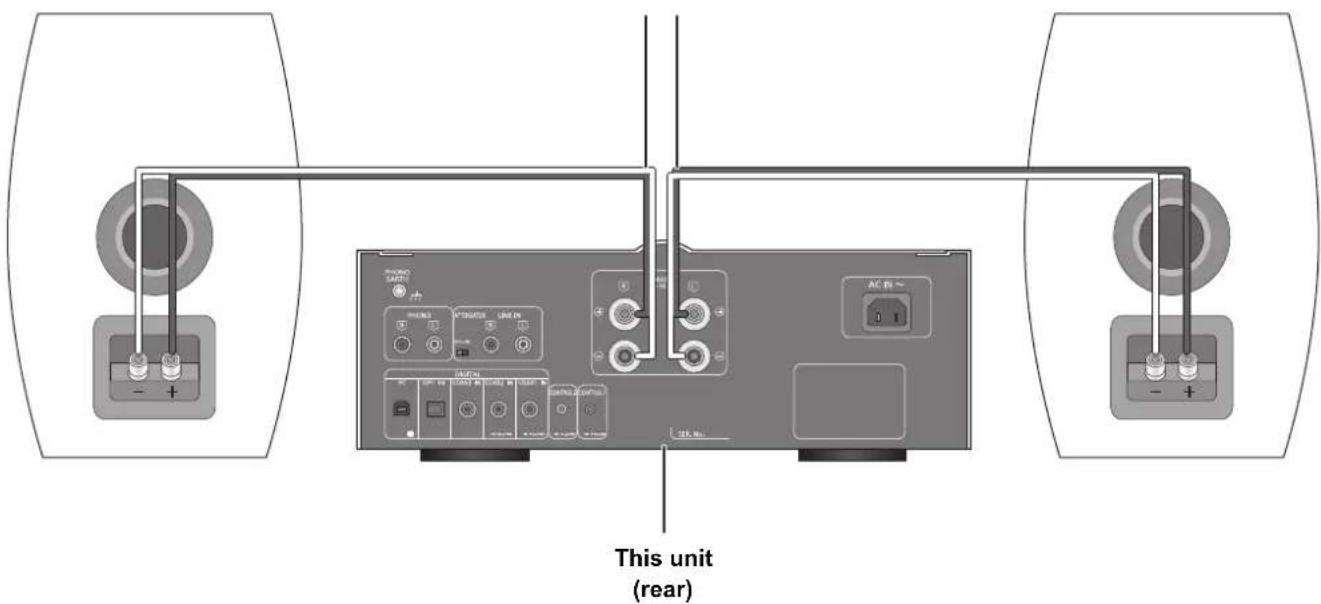
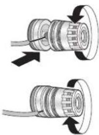
1 Turn the knobs to loosen them, and insert the core wires into the holes.
natural_image
Diagram showing two mechanical components with arrows indicating direction of movement (no text or symbols)2 Tighten the knobs.

- When the connections are completed, pull the speaker cables lightly to check that they are connected firmly.
- Be careful not to cross (short-circuit) or reverse the polarity of the speaker wires as doing so may damage the amplifier.
- Wire the polarity (+/−) of the terminals correctly. Not doing so may adversely affect stereo effects or cause malfunction.
- For details, refer to the operating instructions of the speakers.
DO NOT

natural_image
Pure electrical circuit lines without any symbolsSystem control connection to an ST-C700/SL-C700
- You can input digital audio signals to this unit and play back music.
- You can automatically link this unit with the ST-C700/SL-C700 and operate them easily with the remote control. (→ 14)
SL-C700 System connection cable System connection cable ST-C700

flowchart
graph TD
    A["Device Unit"] --> B["Coaxial digital cable Coaxial digital cable"]
    B --> C["Control Unit"]
    B --> D["Digital Control Unit"]
    B --> E["AC Control Unit"]
    B --> F["COAX OUT Control Unit"]
    B --> G["Control Unit"]
    style A fill:#f9f,stroke:#333
    style B fill:#ccf,stroke:#333
    style C fill:#cfc,stroke:#333
    style D fill:#fcc,stroke:#333
    style E fill:#cff,stroke:#333
    style F fill:#ffc,stroke:#333
    style G fill:#cfc,stroke:#333

- Use the system connection cables and the coaxial digital cables supplied with the ST-C700/SL-C700.
- Connect the system connection cables to the system terminals [CONTROL1]/[CONTROL2]. Connect the ST-C700 to [CONTROL1] and the SL-C700 to [CONTROL2].
- Connect coaxial digital cables to the digital audio input terminals [COAX1 IN]/[COAX2 IN]. Connect the ST-C700 to [COAX1 IN] and the SL-C700 to [COAX2 IN].
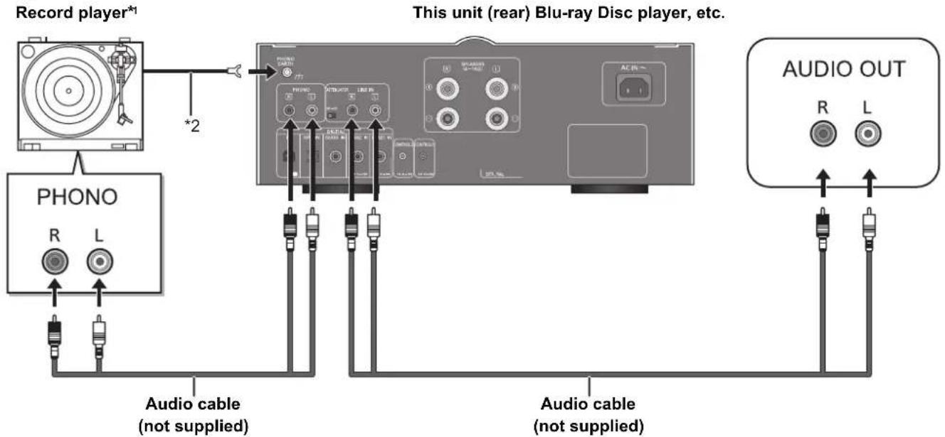
Connecting to analogue audio output devices
You can input analogue audio signals to this unit and play back music.
e.g.,
flowchart
graph TD
    A["Record player*1"] -->|*2| B["This unit (rear) Blu-ray Disc player, etc."]
    C["PHONO"] --> D["Audio cable (not supplied)"]
    E["AUDIO OUT"] --> F["Audio cable (not supplied)"]
    D --> G["Phono Cable"]
    F --> H["Audio Cable"]
    style A fill:#f9f,stroke:#333
    style C fill:#ccf,stroke:#333
    style E fill:#cfc,stroke:#333
*1 When connecting to a record player with a built-in PHONO equalizer, connect its cable to the analogue audio input terminal [LINE IN].
*2 When connecting a record player with a ground wire, connect the ground wire to the PHONO EARTH terminal [PHONO EARTH] of this unit.
Connecting to digital audio output devices
You can input digital audio signals to this unit and play back music.
e.g.,
CD player, etc. This unit (rear) CD player, etc.

flowchart
graph LR
    A["OPTICAL OUT"] --> B["Optical digital audio cable (not supplied)"]
    B --> C["Coaxial digital cable (not supplied)"]
    C --> D["COAXIAL OUT"]

- The digital audio input of this unit supports only the linear PCM (LPCM) signals listed below. For details, refer to the operating instructions of the connected device.
| Input terminal Sampling frequency Number of quantization bits | |
| Coaxial digital input 32/44.1/48/88.2/96/176.4/192 kHz 16/24 bit | |
| Optical digital input 32/44.1/48/88.2/96 kHz 16/24 bit |
AC mains lead connection
Connect only after all other connections are completed.
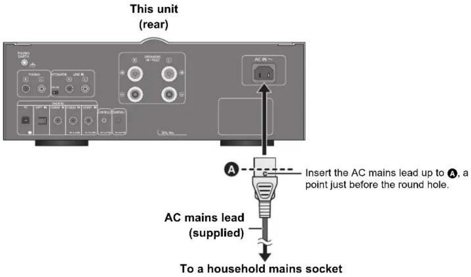

- This unit consumes a small amount of AC power ( 17) even the power switch lever is in the [OFF] position. Remove the plug from the main electrical outlet if you will not be using the unit for an extended period of time. Place the unit so the plug can be easily removed.
Measuring the characteristics of the amplifier and correcting its output
To optimise the audio output, you can measure the amplifier characteristics and correct its output when it is connected to the speakers.
- Disconnect the headphones. If you connect them during amplifier characteristic measurement or amplifier output correction, it will be cancelled.
Test tone emitted during measurement
To ensure the measurement accuracy, the speakers output a test tone at regular intervals. (For approximately 4 minutes)
It is not possible to change the volume of the audio being output while the measurement is in progress.
1 Raise the power switch lever of this unit to the [∅/I] position.
2 Press and hold [LAPC] until the LAPC indicator on this unit starts to blink.
- This unit will start measuring the characteristics of the amplifier. Check that a test tone is output from both the left and right speakers.
- If you press [LAPC] while the measurement is in progress, it will be cancelled. The LAPC indicator on this unit will go off.
- When the measurement is complete, amplifier output correction will be automatically turned on. The LAPC indicator on this unit will light up.
■ Turning on/off the output correction function
Press [LAPC].
Each time you press the button:
| LAPC indicator lights up On | |
| LAPC indicator goes off Off |
![TECHNICS SU-C700EB - Press [LAPC]. - 1](/content/2026/06/1192561/images/9af228f8e7169b89971f993a7975b0bfbe13cb39d168597ea2295d93d9325797.jpg)
- Depending on the type of the connected speakers, the effect of the output correction function may be minimal.
- The corrected output remains in effect until you measure the characteristics again. When you use other speakers, redo the measurement.
Operations
- Reduce the volume to minimum.
1 Raise the power switch lever of this unit to the [⏻/l] position.
2 Press [> INPUT <] below [AMP] to select the input source.
The indicator of the selected input source will light up.
| PHONO Analogue audio input (PHONO) | |
| LINE Analogue audio input (LINE IN) | |
| PC | Digital audio input (PC) ( 15) |
| COAX1 | ●Digital audio input (COAX1 IN)●ST-C700 |
| COAX2 | ●Digital audio input (COAX2 IN)●SL-C700 |
| COAX3 | Digital audio input (COAX3 IN) |
| OPT | Digital audio input (OPT IN) |
3 Operate the device to be used for playback.
4 Press [+ VOL -] to adjust the volume.
Auto off function
This unit is designed to conserve its power consumption and save energy. The unit will turn to standby mode automatically if there is no sound and it is not being used for approximately 20 minutes.
- The factory default is "On".
To cancel this function
1 Press and hold [MUTE] until the PHONO indicator on this unit starts to blink.
2 Press [MUTE].
Each time you press the button:
COAX3 indicator blinks On
OPT indicator blinks Off
3 Press [VOL -] to exit.

- You will exit the auto off setup mode if you do not operate any buttons and controls for approximately 10 seconds after any of the three indicators above starts blinking.
Remote control code
When other equipment responds to the supplied remote control, change the remote control code.
- The factory default is "1".
Point the remote control at this unit, and press and hold [OK] and the numeric button for at least 4 seconds.
- When the code is changed, the PC indicator and the COAX2 indicator blink for approximately 10 seconds.
[OK] + [1] Set the code to 1
[OK] + [2] Set the code to 2

- When the ST-C700/SL-C700 is connected via the system control function, change its remote control code as well as the remote control code for this unit.
Using the system control function
You can automatically link this unit with the ST-C700/SL-C700 and operate them easily with the remote control.
Preparation
① Connect this unit and the ST-C700/SL-C700 with system connection cables and coaxial digital cables. ( 10)
② Set the power switch lever of this unit and the ST-C700/SL-C700 to the [∅/I] position.
■ Switching this unit and the ST-C700/SL-C700 to on/standby simultaneously
- If you point the remote control at this unit and press [AMP ⏻] when this unit and the ST-C700/SL-C700 are in standby mode, this unit and the device of the selected input source will be turned on simultaneously.
- If you point the remote control at this unit and press [AMP ⏻] when this unit and the ST-C700/SL-C700 are turned on, this unit and the ST-C700/SL-C700 will simultaneously enter standby mode.
- Switching this unit's input source automatically
When you perform an operation such as playback on the ST-C700/SL-C700, the input source of this unit will be automatically switched to "COAX1"/"COAX2".

- For information on the operations of the ST-C700/SL-C700, please also refer to their operating instructions.
- If you install the dedicated app "Technics Music App" (free of charge) on your tablet/smartphone, you can use a wide variety of functions when the unit and the ST-C700 are connected.
For details, visit:
www.technics.com/support/
Listening to audio from a PC, etc.
You can connect the digital audio input terminal [PC] and a PC, etc. with a USB cable and play back music on the PC, etc. with this unit.
Connecting to a PC
Before connecting to a PC, follow the steps below.
- Refer to the following for the recommend OS versions for your PC: - Windows Vista, Windows 7, Windows 8, Windows 8.1 - OS X 10.7, 10.8, 10.9, 10.10
① Download and install the dedicated driver to the PC. (Only for Windows OS)
Download and install the driver from the website below.
www.technics.com/support/
② Download and install the dedicated app "Technics Audio Player" (free of charge) on your PC. (Common to both Windows OS and OS X)
Download and install the app from the website below.
www.technics.com/support/
(as of November 2014)
1 Disconnect the AC mains lead.
2 Connect this unit and a PC, etc.
e.g.,

3 Connect the AC mains lead to this unit, and raise the power switch lever to the [⏻/l] position. (⇒ 12)
4 Press [> INPUT <] below [AMP] repeatedly to select "PC".
5 Operate the PC, etc. for playback.
6 Press [+ VOL -] to adjust the volume.
Troubleshooting
Before requesting service, make the following checks. If you are uncertain about some of the check points, or if the solutions indicated in the following guide does not resolve the issue, then consult your dealer for instructions.
To return all settings to the factory defaults
When the following situations occur, reset the memory:
- There is no response when buttons are pressed.
- You want to clear and reset the memory contents.
When the unit is off:
① Press and hold [AMP ⏻].
② While continuing to hold [AMP ⏻], raise the power switch lever of this unit to the [∅/l] position.
- Keep holding [AMP ⏻] until the PC indicator and the COAX2 indicator blink twice.
Heat buildup of this unit.
- This unit becomes warm when the volume is high. This is not a malfunction.
A "humming" sound can be heard during playback.
- An AC mains lead or fluorescent light is near the cables. Keep other appliances and cords away from the cables of this unit.
- Set the [ATTENUATOR] switch to [ON]. (⇒ 7)
- A strong magnetic field near a TV or other device may adversely affect the audio quality. Keep this unit away from such devices.
- The speakers may output noise when a device nearby is emitting powerful radio waves, such as when a mobile phone is on a call.
No sound.
- Check connections to speakers and other equipment. After checking the connections, measure the characteristics of the amplifier. (⇒ 13)
- Check to see if the correct input source is selected.
- Insert the plugs of the cables to be connected all the way in.
- Playback of multi-channel content is not supported.
- The digital audio input terminals of this unit can only detect linear PCM (LPCM) signals. For details, refer to the operating instructions of the connected device.
The remote control does not work properly.
- To avoid interference, please do not put any objects in front of signal sensor. ( 7)
- Change the remote control code if other products react to this remote control. (⇒ 14)
Pressing [DIMMER] changes the display and the basic control switches brightness of the ST-C700/SL-C700.
- [DIMMER] works for the ST-C700/SL-C700 as well as this unit. Turn off the device that you want to maintain the brightness level of, and press [DIMMER].
The peak power meter does not operate.
- In the following cases, this meter does not operate:
- When a headphone plug is connected.
- When the peak power meter light is turned off by pressing [DIMMER].
- When this unit is muted by pressing [MUTE].
The system control function is not working.
- Use the system connection cables supplied with the ST-C700/SL-C700.
- Connect the system connection cables to the system terminals [CONTROL1]/[CONTROL2]. Connect the ST-C700 to [CONTROL1] and the SL-C700 to [CONTROL2].
- Connect coaxial digital cables to the digital audio input terminals [COAX1 IN]/[COAX2 IN]. Connect the ST-C700 to [COAX1 IN] and the SL-C700 to [COAX2 IN].
The unit turns off automatically.
- Is the auto off function turned on? (⇒ 14)
- If the ST-C700 is connected to this unit via the system control function, this unit may automatically enter standby mode when the ST-C700 enters standby mode. (⇒ 10, 14)
- This unit incorporates a protection circuit to prevent damage caused by heat buildup. When you use this unit at a high volume level for a long period of time, it may turn off automatically.
Wait for this unit to cool down before turning on this unit again. (For approximately 3 minutes)
Input indicator blinks.
- In the following cases, the input indicator blinks: - When this unit is muted by pressing [MUTE].
- "PC", "COAX1", "COAX2", "COAX3" or "OPT" is selected, but no device is connected.
– Audio signals, such as sampling frequency components, are not input correctly.
Specifications
GENERAL
Power supply
AC 220 V to 240 V, 50/60 Hz
Power consumption 73 W
Power consumption in standby mode Approx. 0.3 W
Power consumption in off mode Approx. 0.3 W
Dimensions (W×H×D)
Operating temperature range
0^ C to +40^ C
Operating humidity range 35 % to 80 % RH (no condensation)
■ AMPLIFIER SECTION
Output power
45 W + 45 W (1 kHz, T.H.D. 0.3 %, 8 Ω, 20 kHz LPF)
70 W + 70 W (1 kHz, T.H.D. 0.5 %, 4 Ω, 20 kHz LPF)
Load impedance
4 Ω to 16 Ω
Frequency response
PHONO (MM)
20 Hz to 20 kHz (RIAA DEVIATION ±1 dB, 8 Ω)
LINE
20 Hz to 80 kHz ( -3 dB , 8 )
COAX1/2/3
20 Hz to 90 kHz ( -3 dB , 8 )
Input sensitivity/Input impedance
LINE
200 mV / 22 kΩ
PHONO (MM)
2.5 mV / 47 kΩ
■ TERMINALS SECTION
Headphones jack
Stereo, ∅6.3 mm
USB port
USB Standard
USB 2.0 high-speed
USB Audio Class specification
USB Audio Class 2.0, Asynchronous mode
Connector
USB Standard B connector
Format support
LPCM (32/44.1/48/88.2/96/176.4/192 kHz, 16/24/32 bit)
DSD (2.8224 MHz, 5.6448 MHz)
DSD control mode
ASIO Native mode, DoP mode
DSD64/DSD128 playback
Channel
2 ch
Analogue input
Line input
Pin jack
PHONO (MM)
Pin jack
Digital input
Optical digital input
Optical terminal
Coaxial digital input ×3
Pin jack
Format support
LPCM
System port
System control ×2
∅3.5 mm jack

- Specifications are subject to change without notice.
• Mass and dimensions are approximate.
Headquarter Address: Panasonic Corporation
Kadoma, Ósaka, Japan
Importer for Europe: Panasonic Marketing Europe GmbH
Panasonic Testing Centre
Winsbergring 15, 22525 Hamburg, Germany
EU
Panasonic Corporation
Web Site: http://www.panasonic.com
En

- For the United Kingdom and Ireland customers
- Sales and Support Information
- ■ Features of this unit
- Full-digital amplifier with a high-precision jitter reduction circuit and PWM conversion circuit
- LAPC (Load Adaptive Phase Calibration)
- High-speed and lower noise linear power supply
- ■ Recommended devices
- Safety precautions
- WARNING
- Unit
- AC mains lead
- CAUTION
- Placement
- Battery
- Caution for AC Mains Lead
- (For the AC mains plug of three pins)
- Before use
- How to replace the fuse
- Disposal of Old Equipment and Batteries
- Only for European Union and countries with recycling systems
- Note for the battery symbol (bottom symbol):
- Table of contents
- About descriptions in these operating instructions
- Accessories
- ■ Using the remote control
- Unit care
- Control reference guide
- This unit
- ① Power switch lever
- ② Headphones jack
- ③ LAPC indicator ( 13)
- ④ Volume knob
- ⑤ Remote control signal sensor
- ⑥ Input selector knob
- ⑦ Peak power meter
- ⑧ Input indicator ( 13)
- ⑨ PHONO EARTH terminal [PHONO EARTH] (⇒ 11)
- ⑩ Analogue audio input terminal [PHONO] ( 11)
- ⑪ Attenuator [ATTENUATOR]
- ⑫ Analogue audio input terminal [LINE IN] ( 11)
- ⑯ Digital audio input terminal [OPT IN] (⇒ 11)
- Remote control
- ■ Buttons that work for this unit
- ① [AMP ⏻]: Standby/on switch
- ② [AMP]/[NWP]/[CD]: Select the device to be operated
- ■ Buttons that work for the ST-C700/SL-C700
- Getting started
- Speaker connection
- System control connection to an ST-C700/SL-C700
- Connecting to analogue audio output devices
- Connecting to digital audio output devices
- AC mains lead connection
- Measuring the characteristics of the amplifier and correcting its output
- Test tone emitted during measurement
- Press [LAPC].
- Operations
- Auto off function
- To cancel this function
- Remote control code
- Using the system control function
- Preparation
- Listening to audio from a PC, etc.
- Connecting to a PC
- Troubleshooting
- To return all settings to the factory defaults
- When the unit is off:
- Heat buildup of this unit.
- A "humming" sound can be heard during playback.
- No sound.
- The remote control does not work properly.
- Pressing [DIMMER] changes the display and the basic control switches brightness of the ST-C700/SL-C700.
- The peak power meter does not operate.
- The system control function is not working.
- The unit turns off automatically.
- Input indicator blinks.
- Specifications
- GENERAL
- ■ AMPLIFIER SECTION
- ■ TERMINALS SECTION
Brand : TECHNICS
Model : SU-C700EB
Category : Amplifier