
TXP-650 - Video projector TOSHIBA - Free user manual and instructions
Find the device manual for free TXP-650 TOSHIBA in PDF.


| Product Type | Video Projector |
| Brand | Toshiba |
| Model | TXP-650 |
| Dimensions (W x D x H) | 11.8 x 9.8 x 3.9 in (300 x 250 x 100 mm) |
| Weight | 7.7 lb (3.5 kg) |
| Power Consumption | 200 W (typical) |
| Lamp Type | UHP (typical) |
| Lamp Life | 4000 hours (standard mode) |
| Brightness | 2000 ANSI lumens |
| Resolution | XGA (1024 x 768) |
| Contrast Ratio | 2000:1 (typical) |
| Input Connectors | VGA, S-Video, Composite, Audio |
| Projection Distance | 4.9 - 39 ft (1.5 - 12 m) |
| Projection Screen Size | 40 - 300 in diagonal |
| Keystone Correction | Vertical ±30° |
| Cooling System | Fan with filter |
| Safety Features | Auto power-off, overheating protection |
| Replacement Parts | Lamp, air filter |
| Repairability Index | 7.0 / 10 (estimated) |
| User Manual Format | PDF, 52 pages |
Frequently Asked Questions - TXP-650 TOSHIBA
User questions about TXP-650 TOSHIBA
0 question about this device. Answer the ones you know or ask your own.
Ask a new question about this device
Download the instructions for your Video projector in PDF format for free! Find your manual TXP-650 - TOSHIBA and take your electronic device back in hand. On this page are published all the documents necessary for the use of your device. TXP-650 by TOSHIBA.
USER MANUAL TXP-650 TOSHIBA
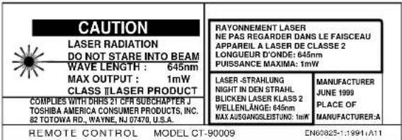
CAUTION: Laser beam is emitted when the laser button of the remote control is pressed. Do not look from the front of the remote control. Do not face toward a person or to a mirror.

The lightning flash with arrowhead symbol, within an equilateral triangle, is intended to alert the user to the presence of uninsulated “dangerous voltage” within the product’s enclosure that may be of sufficient magnitude to constitute a risk of electric shock to persons.

The exclamation point within an equilateral triangle is intended to alert the user to the presence of important operating and maintenance (servicing) instructions in the literature accompanying the appliance.
IMPORTANT PRECAUTIONS
Save Original Packing Materials
The original shipping carton and packing materials will come in handy if you ever have to ship your LCD projector. For maximum protection, repack the set as it was originally packed at the factory.
Avoid Volatile Liquid
Do not use volatile liquids, such as an insect spray, near the unit. Do not leave rubber or plastic products touching the unit for a long time. They will mar the finish.
Moisture Condensation
Never operate this unit immediately after moving it from a cold location to a warm location. When the unit is exposed to such a change in temperature, moisture may condense on the crucial internal parts. To prevent the unit from possible damage, do not use the unit for at least 2 hours when there is an extreme or sudden change in temperature.
In the spaces provided below, record the Model and Serial No. located at the rear of your LCD projector.
Model No. ____ Serial No. ____
Retain this information for future reference.
IMPORTANT SAFETY INSTRUCTIONS
CAUTION: PLEASE READ AND OBSERVE ALL WARNINGS AND INSTRUCTIONS GIVEN IN THIS OWNER'S MANUAL AND THOSE MARKED ON THE UNIT. RETAIN THIS BOOKLET FOR FUTURE REFERENCE.
This set has been designed and manufactured to assure personal safety. Improper use can result in electric shock or fire hazard. The safeguards incorporated in this unit will protect you if you observe the following procedures for installation, use and servicing. This unit is fully transistorized and does not contain any parts that can be repaired by the user.
DO NOT REMOVE THE CABINET COVER, OR YOU MAY BE EXPOSED TO DANGEROUS VOLTAGE. REFER SERVICING TO QUALIFIED SERVICE PERSONNEL ONLY.
1. Read Owner's Manual
After unpacking this product, read the owner's manual carefully, and follow all the operating and other instructions.

2. Power Sources
This product should be operated only from the type of power source indicated on the marking label. If you are not sure of the type of power supply to your home, consult your product dealer or local power company. For products intended to operate from battery power, or other sources, refer to the operating instructions.

3. Source of Light
Do not look into the lens while the lamp is on. The strong light from the lamp may cause damage to your eyes or sight.

4. Ventilation
Openings in the cabinet are provided for ventilation and to ensure reliable operation of the product and to protect it from overheating, and these openings must not be blocked or covered. The openings should never be blocked by placing the product on a bed, sofa, rug or other similar surface. This product should not be placed in a built-in installation such as a bookcase or rack unless proper ventilation is provided or the manufacturer's instructions have been adhered to.

IMPORTANT SAFETY INSTRUCTIONS
5. Heat
The product should be situated away from heat sources such as radiators, heat registers, stoves, or other products (including amplifiers) that produce heat.

7. Cleaning
Unplug this product from the wall outlet before cleaning. Do not use liquid cleaners or aerosol cleaners. Use a damp cloth for cleaning.
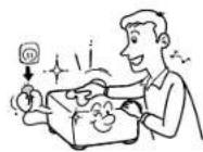
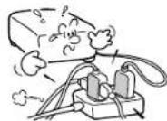
9. Overloading
Do not overload wall outlets; extension cords, or integral convenience receptacles as this can result in a risk of fire or electric shock.
6. Water and Moisture
Do not use this product near water – for example, near a bath tub, wash bowl, kitchen sink, or laundry tub; in a wet basement; or near a swimming pool and the like.

8. Power-Cord Protection
Power-supply cords should be routed so that they are not likely to be walked on or pinched by items placed upon or against them, paying particular attention to cords at plugs, convenience receptacles, and the point where they exit from the product.
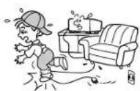
10. Lightning
For added protection for this product during storm, or when it is left unattended and unused for long periods of time, unplug it from the wall outlet.
This will prevent damage to the product due to lightning and power-line surges.

IMPORTANT SAFETY INSTRUCTIONS
11. Object and Liquid Entry
Never push objects of any kind into this product through openings as they may touch dangerous voltage points or short-out parts that could result in a fire or electric shock. Never spill liquid of any kind on the product.

12. Do not place the product vertically
Do not use the product in the upright position to project the pictures at the ceiling, or any other vertical positions. It may fall down and dangerous.

natural_image
Cartoon illustration of a computer monitor with arms and legs, showing motion lines around it (no text or symbols)13. Stack Inhibited
Do not stack other equipment on this product or do not place this product on the other equipment.
Top and bottom plates of this product develops heat and may give some undesirable damage to other unit.

14. Attachments
Do not use attachments not recommended by the product manufacturer as they may cause hazards.
15. Accessories
Do not place this product on an unstable cart, stand, tripod, bracket, or table. The product may fall, causing serious injury to a child or adult, and serious damage to the product. Use only with a cart, stand, tripod, bracket, or table recommended by the manufacturer, or sold with the product. Any mounting of the product should follow the manufacturer's instructions, and should use a mounting accessory recommended by the manufacturer.
A product and cart combination should be moved with care. Quick stops, excessive force, and uneven surfaces may cause the product and cart combination to overturn.

IMPORTANT SAFETY INSTRUCTIONS
16. Damage Requiring Service
Unplug this product from the wall outlet and refer servicing to qualified service personnel under the following conditions:
a) When the power-supply cord or plug is damaged.
b) If liquid has been spilled, or objects have fallen into the product.
c) If the product has been exposed to rain or water.
d) If the product does not operate normally by following the operating instructions. Adjust only those controls that are covered by the operating instructions as an improper adjustment of other controls may result in damage and will often require extensive work by a qualified technician to restore the product to its normal operation.
e) If the product has been dropped or damaged in any way.
f) When the product exhibits a distinct change in performance – this indicates a need for service.
17. Servicing
Do not attempt to service this product yourself as opening or removing covers may expose you to dangerous voltage or other hazards. Refer all servicing to qualified service personnel.
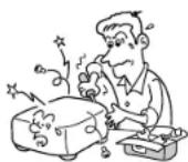
18. Replacement Parts
When replacement parts are required, be sure the service technician has used replacement parts specified by the manufacturer or have the same characteristics as the original part. Unauthorized substitutions may result in fire, electric shock, or other hazards. (Replacement of the lamp only should be made by users.)
19. Safety Check
Upon completion of any service or repairs to this product, ask the service technician to perform safety checks to determine that the product is in proper operating condition.

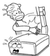
20. Do not get your hands between the camera arm and the main unit when setting the camera arm back in its original position.
To avoid injury, be careful not to get your hands caught when setting the camera arm back in its original position. Families with children should be particularly careful.
IMPORTANT SAFETY INSTRUCTIONS
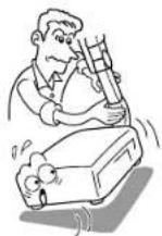
21. Do not carry by the camera arm.
Do not carry the projector by the camera arm.
Doing so can result in damage or injury.
22. Do not leave documents on the unit for long periods of time while using the document imaging function.
Do not leave texts, papers or other documents for projection on the unit for long periods of time. The heat could erase the letters on a thermal paper.

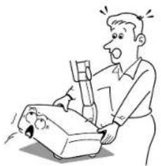
23. Do not move the projector while the arm is still erect.
Always store the arm back in position when moving the projector. Otherwise injury or damage may result.
natural_image
Cartoon illustration of a man reacting to a sad, broken object (no text or symbols present)Before use
Power supply cord selection
If your line voltage is 220 to 240, use one of the following types of cable.
Plug
configuration
Plug type
Line voltage
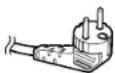
EURO
220-240V
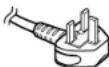
UK
220-240V
Use a 5A fuse which is approved by ASTA or BSI to BSI362.
Always replace the fuse cover after changing the fuse.
CONTENTS
Before use
CONTENTS
Contents
Before use
SAFETY PRECAUTIONS 2
IMPORTANT PRECAUTIONS.... 3
IMPORTANT SAFETY INSTRUCTIONS 4
Power supply cord selection 9
Part names and functions 11
Connections and installation
Connections 16
Projector placement 18
Operations
Picture projection 21
Operating the computer by the remote control.... 25
Adjustments
Setting and adjustments on the menu.... 27
Initial settings - Default 28
Keystone correction - Keystone 30
Projection adjustments - Image.... 31
Picture adjustments - Picture 32
Sound adjustments - Audio 33
Saving data - Save 34
Camera
Part names and functions of document imaging camera .... 35
Picture projection with the document imaging camera 37
Overlaying projection 39
Maintenance
Trouble indications 40
Air filter, lens and main unit cleaning 41
Lamp replacement 42
Others
Before calling service personnel 43
Input signal 45
Adjustments with RS-232C 49
Specifications 51
Before use
CONTENTS
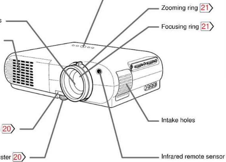
Part names and functions
Main unit
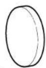
Lens cover
Projection lens
Exhaust holes
Foot adjuster
release button
Control panel

1 ON/STANDBY button 21
To turn the projector on or off.
2 MENU button 27
To display or close the menu.
3 SELECT/ADJUST button 28

To select items or adjust values on the menu.
4 ENTER button 30
To enter your selection on the menu.
5 INPUT button 21
To select the input source.
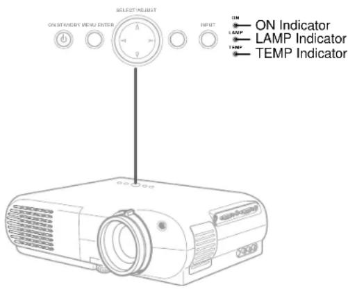
6 ON indicator 21 40
7 LAMP indicator 21 40
8 TEMP indicator 40
(Continued)
Before use
(Continued)
CONTENTS
Left side Right side

Rear side

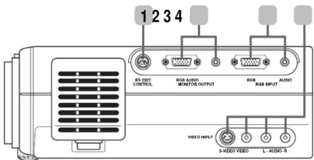
1 CONTROL connector 17 49 To connect a computer to control the projector.
2 MONITOR OUTPUT connectors (RGB output, AUDIO output) 17 To connect to a monitor or audio equipment.
3 RGB INPUT connectors (RGB input, AUDIO input) 16
To connect a computer, etc.
4 VIDEO INPUT connectors
(S-VIDEO input, VIDEO input, AUDIO input) 17
To connect a video equipment, etc.
(Continued)
Before use
(Continued)
Remote control
Caution - use of controls or adjustments or performance of procedures other than those specified herein may result in hazardous radiation exposure.
CONTENTS
Location of the labels



* Functions when the POINTER/PJ selector is set to "POINTER".
1 AUTO SET button 23
To adjust the image automatically.
2 KEYSTONE button 22
To correct the keystone distortion of the picture automatically.
3 MARKER button
To display a marker on the screen.
Each time the button is pressed, the marker changes the shape, and finally disappears.

natural_image
Line drawing of a remote control device with buttons and a black arrow indicating left side (no text or symbols)4 POINTER/PJ selector 26
To switch the operation modes of the remote control.
POINTER: To operate a computer. (The supplied REMOTE MOUSE RECEIVER should be connected to the computer.) PJ: To operate the projector.
5 ▲, ▼, ◀(−), ▶(+) button 28/ Pointer control* 26
- To select items or adjust values on the menu.
- To shift a picture after changing its size with the RESIZE button.
• To move the marker displayed with the MARKER button.
• To move the pointer of the computer.* - To substitute for the L-CLICK button by pressing the center.*
(Continued)
Before use
CONTENTS

(Continued)
6 L-CLICK button* 26 / MENU button 28
- To left-click.*
• To display or close the menu.
7 RGB button 21
To select the RGB input.
8 RESIZE button 24
To change the picture size.
9 ON/STANDBY button 21
To turn the projector on or off.
10 LASER button
To display the laser pointer by pointing the laser emission part toward the screen.
11 R-CLICK button* 26 / ENTER button 28
- To right-click.*
• To enter your selection on the menu.
12 VIDEO button 21
To select the video input.
13 CAMERA button (for document imaging camera model only) 37
To select the camera input.
14 RESET button 29
To restore the settings and adjustments to the default.
15 FREEZE button 23
To freeze the picture.
16 MUTE button 23
To cut off the picture and sound temporarily.
17 CALL button 23
To display the current input source and signal status information.
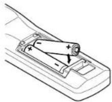
Installing batteries
1) Open the cover.

natural_image
Line drawing of a car seatbelt mechanism (no text or symbols)2) Install the batteries.
Make sure that the +/- polarities match the illustration in the compartment.
natural_image
Diagram of a car's battery pack with arrows indicating direction (no text or symbols)3) Attach the cover.
(Continued)
Before use
(Continued)
Notes
Using batteries incorrectly can cause them to leak or burst. Strictly observe the following.
- Install the batteries with their + and - ends facing correctly.
- Do not charge, heat, disassemble, or short the batteries or throw them into a fire.
- Do not leave exhausted batteries in the remote control.
- Do not mix different types of batteries or new and old batteries.
- When you will not be using the remote control for a prolonged period, take the batteries out of the remote control.
- When the remote control stops working or only works from very close distance, replace all the batteries with new ones.
- When replacing the batteries, use a more longer life alkaline batteries.
- If a battery leaks, carefully wipe off any residue inside the battery case before loading new batteries.
Remote control operation
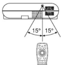
Point the remote control at the infrared remote sensor and press a button.
Front side

Rear side
Rear side (document imaging camera model)

Distance : within about 5 meters from the front of the remote sensor.
Angle : within about 15° of the remote sensor in every direction.
CONTENTS
Notes
- The remote control may not operate when there is sunlight or other strong light such as a fluorescent lamp shining on the remote sensor.
- Operate the remote control from a position where the remote sensor is visible.
- Do not drop the remote control or otherwise jolt it.
- Keep the remote control out of locations with excessively high temperature or humidity.
- Do not get water on the remote control or place wet objects on it.
- Do not disassemble the remote control.
- Under unusual circumstances the remote control may not operate well due to the location being used or the surroundings. At such times, change the direction of the remote control to the projector and retry the operation.
Connections
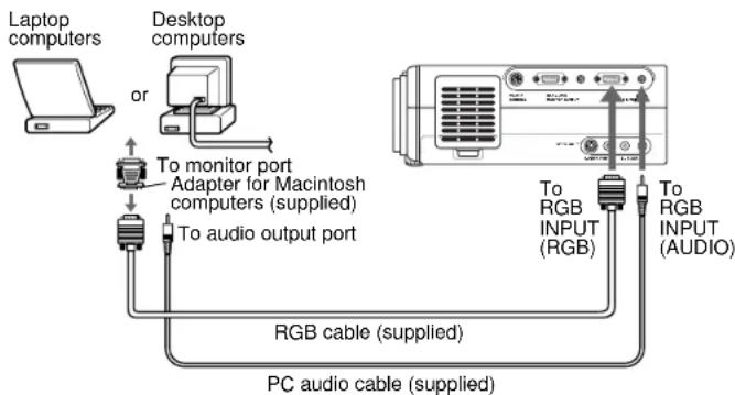
Connecting an IBM PC or compatible computer (DOS/V)
Check that the power for the projector and computer is off before connecting the cables.

flowchart
graph TD
    A["Laptop computers"] --> B["or"]
    B --> C["Computer monitor cable"]
    C --> D["To monitor port"]
    C --> E["To audio output port"]
    F["Desktop computers"] --> G["Connect when you want to view a picture on the computer monitor."]
    G --> H["To monitor OUTPUT (RGB)"]
    G --> I["To RGB INPUT (AUDIO)"]
    H --> J["RGB cable (supplied)"]
    I --> J
    J --> K["PC audio cable (supplied)"]
Notes
- The projector cannot be connected to a computer that does not have an analog RGB output terminal. For details, refer to the computer manual.
- You may not be able to connect some computers to the projector. For details, consult the dealer.
- If NTSC/PAL/SECAM signals are input to the RGB INPUT connector, they cannot be displayed. (Input NTSC/PAL/SECAM signals to the VIDEO INPUT jack.)
Connecting a Macintosh computer
- Attach the supplied adapter for Macintosh computers.
- Check that the power for the projector and computer is off before connecting the cables.
flowchart
graph TD
    A["Laptop computers"] --> B["Desktop computers"]
    B --> C["To monitor port"]
    C --> D["Adapter for Macintosh computers (supplied)"]
    D --> E["To audio output port"]
    E --> F["RGB cable (supplied)"]
    F --> G["PC audio cable (supplied)"]
    H["Computer with RGB INPUT (RGB)"] --> I["To RGB INPUT (AUDIO)"]
    I --> J["Output"]
Notes
- The projector cannot be connected to a computer that does not have an analog RGB output terminal. For details, refer to the computer manual.
- You may not be able to connect some computers to the projector. For details, consult the dealer.
- The adapter for Macintosh computers is conformable to MULTIPLE SCAN 21.
(Continued)
Connections and installation
(Continued)
CONTENTS
Connecting video equipment
Check that the power for the projector and computer is off before connecting the cables.

Note
Signal input to the S-VIDEO jack takes priority over that to the VIDEO jack.
Output terminals
Check that the power for the projector and computer is off before connecting the cables.

flowchart
graph TD
    A[" projector"] -->|You can connect a computer to control the projector. 49| B[" Audio cable (not supplied) "]
    C[" Computer"] -->|You can connect an extra monitor to view the picture. | B
    B -->|To audio input| D[" Audio system with connected audio cable"]
    D --> E[" Connect a stereo system for dynamic sound. "]
    E --> F[" Speaker "]
    style A fill:#f9f,stroke:#333
    style C fill:#ccf,stroke:#333
    style D fill:#cfc,stroke:#333
    style E fill:#fcc,stroke:#333
Notes
- Sound of the source which you select is output to the connected stereo system, etc.
- The MONITOR OUTPUT connector always sends out a signal which is input to the RGB INPUT connector regardless of your source selection.
- Even while the projector is in standby mode, the MONITOR OUTPUT connector continues its output.
Connections and installation
CONTENTS
Projector placement
There are four ways of installing this projector as shown right. This section explains the standard case of the floor-mounted front projection.
CAUTION
- When a ceiling mount is required, please consult with the dealer.
- When carrying the unit, always handle the carrying handle.
Preparation
- Select a room that can be darkened.
• Refer to the table on the next page 19 for the screen size and required distance.
Floor-mounted front projection
Viewing a picture projected on the front of the screen from a floor.

Floor-mounted rear projection
Viewing a picture projected through the back of the screen from a floor installation.
Translucent screen
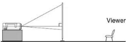
Ceiling-mounted front projection
(The document imaging camera model could not be mounted on the ceiling.) Viewing a picture projected on the front of the screen from a ceiling installation.
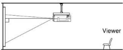
Ceiling-mounted rear projection
(The document imaging camera model could not be mounted on the ceiling.) Viewing a picture projected through the back of the screen from a ceiling installation.
Translucent screen

- When installed the projector in the way except the floor-mounted front projection, make the setting of the projecting orientation on the menu. 28
(Continued)
Connections and installation
(Continued)
1 Place the projector on a steady, level surface such as a table.
Point the projector squarely at the screen for the best possible picture.

Point the lens straight at the center of the screen as above.

Place the projector horizontally so that the projecting light hits the screen squarely.
CONTENTS
2 Adjust the distance between the lens and the screen.
The projection size depends on the distance between the lens and the screen.
Adjust the projection size by changing the distances as shown below.

a: Distance between the lens and the screen
b: Distance between the lens height and the bottom of projection area
| Screen size (inches) | a (m) | b (cm) | |
| Minimum (WIDE) | Maximum (TELE) | ||
| 23 | - | 1.132 | 4 |
| 40 | 1.56 | 2.017 | 6 |
| 60 | 2.373 | 3.059 | 9 |
| 80 | 3.186 | 4.1 | 12 |
| 100 | 3.999 | 4.142 | 15 |
| 150 | 6.031 | 7.746 | 23 |
| 200 | 8.064 | 10.35 | 30 |
| 250 | 10.096 | - | 38 |
• The values are approximations.
3 Connect the power cord.
- Insert one end in the AC IN socket on the projector.
- Insert the other end in a wall outlet.

The ON indicator lights in orange and the projector turns to standby mode.
4 Take off the lens cover.
(Continued)
Connections and installation
(Continued)
Notes
- When the projector is moved from a cold location to a warm location, or when the ambient temperature in the projection room has risen suddenly, moisture may condense on the lens or the mirror to blur the projected pictures. In such a case, leave the projector for an adequate time (1 to 2 hours, depending on the room's condition) before using it so it adjusts to the ambient temperature.
- If the screen is exposed to direct sunlight or other strong light, the projected picture becomes too faint to see. Shut out the light with curtains or other means.
- If the screen and the projector are not installed properly, the projected picture may be distorted.
- If the projector is tilted, the picture may be distorted. To obtain the best possible picture, place the projector so it faces the screen squarely.
How to use the foot adjuster
The tilt of the projector can be adjusted using the foot adjuster.
1) Lift the front of the projector until a tilt angle desired is obtained and hold down the foot adjuster release button.
The foot adjuster will stretch.
Release the button to lock in position.

2) Turn the foot adjuster to make fine adjustment of the height.
Turn clockwise to lift up. Turn counterclockwise to lower.

CONTENTS
3) To put the foot adjuster back, hold down the foot adjuster release button and lower the front slowly.
The foot adjuster will put back.
Note
Be sure to hold the projector when putting the foot adjuster back so as not to let the front fall on your fingers.
Operations
Picture projection
CAUTION
Do not look into the projection lens while operating the projector.
Preparation
- Install and connect the projector properly.
• Take off the lens cover. - Set the POINTER/PJ to "PJ".


1 Press ON/STANDBY.
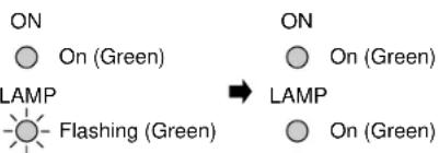
Both the ON and LAMP indicators light up in green.
2 Turn on the connected equipment and put it in playback mode.
CONTENTS
3 Select the input source.
(On the remote control)
Press RGB or VIDEO.
(On the control panel of the main unit)
Press INPUT repeatedly.
Each time the button is pressed, the source indication on the screen changes as follows:

4 Adjust the picture size by turning the zooming ring.
Turn to the right to enlarge the picture. Turn to the left to reduce the picture.
5 Focus on the picture by turning the focusing ring.
A still picture is recommended for focusing.
(Continued)
Operations
(Continued)
Notes
- “ _V^ ” is displayed on the screen if the projector does not receive any signal from the connected equipment. Put the equipment in playback mode.
- Due to the lamp characteristic, flickers may occasionally occur in a picture. This is not malfunction of the unit.
- When an RGB source is selected and no signal is sent from the computer for about 30 minutes, the projector turns to standby mode for power saving. It automatically turns on when the signal resumes. Pressing ON/STANDBY also turns it on.
- While operating the projector, “☐” may be displayed on the screen. This means that the operation cannot be completed.

IndicatorsON/STAN
[Non-Text]

Turning the power off
1) Press ON/STANDBY after using the projector.
An instruction message appears.
2) Press ON/STANDBY again.
The LAMP indicator turns off, and the projector turns to standby mode. (The ON indicator lights in orange.)
3) After confirming the exhaust fan stops, unplug the power cord.
The ON indicator turns off.
CONTENTS
22
Notes
• Even after turning the power off, the intake and exhaust fans continue to work for about 3 minutes more to cool the inside of the projector.
- Immediately after the power off, the projector may not be turned on while the LAMP indicator is flashing in green.
Before unplugging the power cord, make sure that the fans are stopped.
Correcting the keystone distortion
A picture may be expanded on the upper side if projected upward from the projector lifted up by the foot adjuster. The projector can correct this keystone distortion automatically.
Press KEYSTONE.
The keystone distortion is corrected automatically.
To correct further, make the "Keystone" adjustment on the menu. 30
(Continued)
Operations
(Continued)
Adjusting the image automatically
An image which is flickering, blurred or is not centered, can be adjusted automatically.
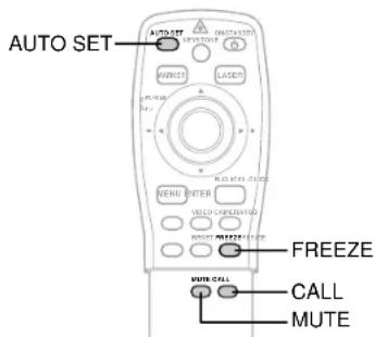
Press AUTO SET.
The image is adjusted automatically.
To adjust further, make the "Image" adjustment on the menu. 31
Cutting off the picture and sound temporarily
1) Press MUTE.
The sound is cut off temporarily.
“” appears.
2) Press MUTE again.
The picture is also cut off temporarily.
“ ” appears.
To restore, press MUTE again.
Note
If you press MUTE while the menu is displayed, the menu disappears.
Freezing the picture
Press FREEZE.
The picture freezes.
“Ⅲ” mark appears on the up right corner of the screen.
To release the picture, press FREEZE again.
Any other operations can also release the picture.
Note
This function is convenient for the case where you are using the document imaging camera model and change documents to project through the camera.
Displaying the input source information
Press CALL.
The current input source and the signal status information is displayed.
To close the display, press CALL again.
CONTENTS
Contents of displayed items
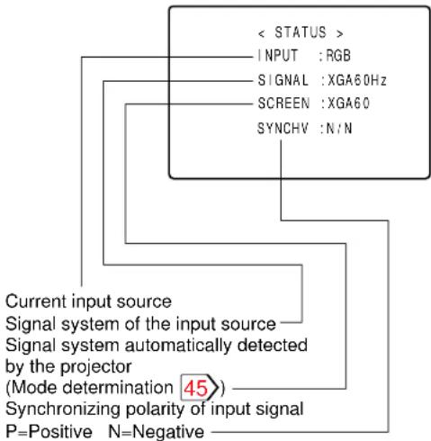
Note
If you press CALL while the menu is displayed, the menu disappears.
Operations
(Continued)
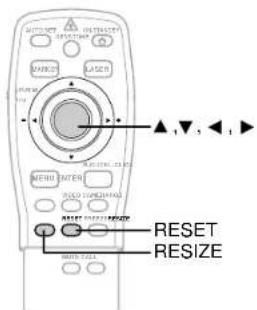
Changing the picture size
Pictures are projected at the maximal projection size regardless of the signal types. Optionally you can change the picture size to through size or enlarge it.
Press RESIZE.
Each time the button is pressed, the picture size changes from the center of the picture.
When the picture size does not correspond with the projection area, the picture can be moved by pressing ▲, ▼ and . ▶
When the picture size is smaller than the projection area:
▲ : To move the picture upward
▼: To move the picture down
◀: To move the picture leftward
▶ : To move the picture rightward
When the picture size is larger than the projection area:
▲ : To view the upper side of the picture
▼: To view the lower side of the picture
◀: To view the left side of the picture
▶ : To view the right side of the picture
Notes
• Picture size returns to normal after the power is turned off. The values are not saved.
- You may not change the picture size depending to the signal.
- Pictures of VGA signals, etc. may be slightly inferior in quality at the initial size because they are enlarged.
- The picture returns to the normal position when the RESET button is pressed after the picture is moved.
- The picture may not be projected properly while moving the picture.
CONTENTS
Operations
Operating the computer by the remote control
If you connect the iREMOTE MOUSE RECEIVER to the computer, the supplied remote control can work as a mouse of the computer.
Connecting the REMOTE MOUSE RECEIVER
Check that the power of the computer is turned off.
Connect the REMOTE MOUSE RECEIVER.
Remove the mouse actually used and change it to the supplied cable.

flowchart
graph TD
    A["Remote Mouse Receiver (supplied)"] --> B["PS/2 Mouse adapter (supplied)"]
    A --> C["IBM/MAC Mouse cable (supplied)"]
    B --> D["USB Mouse cable (supplied)"]
    C --> E["PS/2 Mouse adapter (supplied)"]
    C --> F["IBM/Mac Mouse Cable (supplied)"]
    D --> G["USB PORT"]
    E --> H["PS/2 Mouse Port"]
    F --> I["MAC Mouse Adapter (supplied)"]
    G --> J["IBM PC DOS/V"]
    H --> K["MAC Mouse Port"]
    I --> L["Macintosh"]
CONTENTS
Notes
• To operate the projector and the computer by the remote control, place the REMOTE MOUSE RECEIVER close to the projector.
- When connecting the REMOTE MOUSE RECEIVER to an IBM PC/DOS V computer, use the supplied PS/2 mouse adapter if you are using a PS/2 mouse, or connect the supplied IBM/MAC cable directly to your computer if you are using a serial mouse.
- When connecting the REMOTE MOUSE RECEIVER to the USB PORT for the first time, insert the "Windows98 CD-ROM" and install the device drivers for a USB interchangeability device and a USB human interface devices (two kinds). The installation starts automatically when you connect a USB mouse cable connected to the remote mouse receiver to the USB port of your computer.
(Continued)
Operations
(Continued)
Operating the computer by the remote control
Use the supplied remote control pointing it at the connected REMOTE MOUSE RECEIVER.

Preparation
Set the POINTER/PJ selector to "POINTER".
To move the pointer
Press the pointer control.
The pointer moves to the pressed direction.
To left-click
Press L-CLICK.
To right-click
Press R-CLICK.
To drag and drop
While holding down the center of the pointer control, press the rim and release the center.
Notes
- The remote control operating range is about 5 meter from the front of the remote sensor.
- The remote control may not operate when there is sunlight or other strong light such as a fluorescent lamp shining on the remote sensor.
Adjustments
Settings and adjustments on the menu
Most of adjustments and settings are made on the menu.
To display the menu, press MENU.


The followings are adjustments and settings on the menu. For details, see page in □.
When using this projector for the first time, see "Default". 28

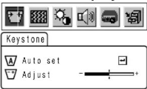
Keystone

Auto set : To correct the keystone distortion automatically.
Adjust : To make the correction of keystone distortion beyond the automatic correction.

Image

Auto sync.: To adjust the image automatically.
Phase : To adjust the phase.
H-position : To shift the image position horizontally
V-position : To shift the image position vertically.
Clock : To adjust the clock frequency.

Picture

Contrast : To adjust the contrast.
Brightness : To adjust the brightness.
Color : To adjust the color depth.
Tint : To adjust the tint.
Sharpness : To adjust the sharpness.
R-level : To adjust the amount of red in the picture.
G-level : To adjust the amount of green in the picture.
B-level : To adjust the amount of blue in the picture.
Camera gain: To adjust the sensitivity of the document imaging camera. (For document imaging camera model only)

Audio

Volume : To adjust the sound volume of the speaker.
CONTENTS
Bass : To adjust the bass of the sound output.
Treble : To adjust the treble of the sound output.

Default

Language : To select the language for displays.
Proj. mode : To set the projecting orientation according to the way of installation.
RGB input : To set the signal type of RGB input.
Video signal : To set the signal type of video input.
Scrn display : To use or disable on-screen displays.

Save

Save data : To save the adjustments and settings on the menu.
All preset : To restore the adjustments and settings on the menu to the factory set.
Adjustments
Initial settings
- Default
Make the basic settings for projecting.
Preparation
- Display the image as explained in "Picture Projection". 21
- Set the POINTER/PJ selector to "PJ".

1 Press MENU to display the menu.
2 Press ◀ or ▶ to select
Default
Language English
proj.mode Standard
RGB input RGB
Video signal Auto
Scrn displayOn
3 Press ▲ or ▼ to select a preferred item.
4 Press ◀ or ▶ to make the setting.
To select another item, go back to step 3. Language
Select a language for the menu or on-screen displays.
English: English
日本語:Japanese
Français: French
Deutsch: German
Italiano : Italian
Español: Spanish
Português : Portuguese
CONTENTS
Proj. mode
Confirm your installation type on the chart on page 18.
Standard: Floor-mounted front projection
Ceiling: Ceiling-mounted front projection
Rear: Floor-mounted rear projection
R. ceil.: Ceiling-mounted rear projection
RGB input
To set the signal type of RGB input.
RGB: RGB signal
Y/Pb/Pr: Color difference (Component) video signal from the DVD video player, etc.
Video signal
To set the signal type of video input.
Auto: Automatic signal detection works on video input. If it does not properly, set the signal type of the source from the followings.
NTSC M: NTSC M signal
NTSC443A: NTSC4.43A signal
NTSC J: NTSC J signal
NTSC N: NTSC N signal
NTSC443B: NTSC4.43B signal
PAL: PAL signal
PAL N: PAL N signal
SECAM: SECAM signal
PAL443: PAL4.43 signal
PAL M: PAL M signal
(Continued)
Adjustments
(Continued)
Scrn display
On: On-screen displays (indications of input selection, signal absent or mute mode, etc.) appear.
Off: On-screen displays do not appear.
5 Press MENU.
The menu disappears.
Notes
• These settings are stored until you turn the power off.
- To store the settings even if the power is turned off, follow the procedure of "Saving data". 34
- Pressing RESET will return all the adjustments or settings currently displayed to their default.
CONTENTS
Adjustments
Keystone correction - Keystone
Preparation
- Display the image as explained in "Picture Projection". 21
- Set the POINTER/PJ selector to "PJ".

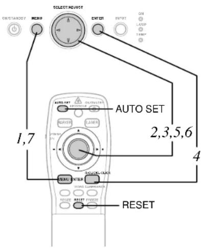
1 Press MENU to display the menu.

3 Press ▼to select "Auto set".
4 Press ENTER.
The keystone distortion is corrected automatically. For further correction, follow the below steps.
5 Press ▼
6 Press or to correct the distortion.
◀ (−): To reduce the upper width.
▶ (+): To expand the upper width.
7 Press MENU.
The menu disappears.
CONTENTS
Notes
- Pressing KEYSTONE on the remote control can also correct the keystone distortion automatically. 22
• These adjustments are stored until you turn the power off. - Pressing RESET will return all the adjustments or settings currently displayed to their default.
- Pictures may be slightly deteriorated by the keystone correction.
Adjustments
Projection adjustments - Image
Preparation
- Display the image as explained in "Picture Projection". 21
- Set the POINTER/PJ selector to "PJ".
1 Press MENU to display the menu.
2 Press ← or → to select .
1 Press MENU to display the menu.
2 Press ← or → to select .
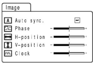
3 Press ▼to select "Auto sync."
4 Press ENTER.
The image is automatically adjusted. For further adjustments, follow the below steps.
5 Press ▲ or ▼ to select a preferred item.
6 Press ◀ or ▶ to adjust the item.
To select another item, go back to step 5.
Phase: To reduce flickers.
H-position: To shift the image to the left (−), to the right (+).
V-position: To shift the image down (−), to up (+).
Clock To remove vertical stripes.
7 Press MENU.
The menu disappears.
CONTENTS
Notes
- Pressing AUTO SET on the remote control can also adjust the image automatically. 23
- If you project an image from a computer with an LCD screen while monitoring the image on the computer, the image may not be projected properly, depending on the computer model. In this case, turn off the computer display, or make the necessary picture adjustments on the projector. For details on controlling the computer display, etc., refer to the computer's manual and description on the software for the computer used.
- During adjustments of "H-position" or "V-position", the image may not be projected properly.
- While using, an aberration of the phase may occur. In that case, adjust "Phase" again.
• These adjustments are stored until you turn the power off. - To store the adjustments even if the power is turned off, follow the procedure of "Saving data". 34
- Pressing RESET will return all the adjustments or settings currently displayed to their default.
Adjustments
Picture adjustments – Picture
Preparation
- Display the image as explained in "Picture Projection". 21
- Set the POINTER/PJ selector to "PJ".

1 Press MENU to display the menu.
2 Press


3 Press ▲or ▼ to select a preferred item.
4 Press ◀ or ▶ to adjust the item.
To select another item, go back to step 3.
\- : ◀ + : ▶
Contrast : (−) Lower
(+) Higher
Brightness: (−) Darker
(+) Brighter
Color: (−) Duller
(+) Brighter
Tint: (−) Redder
(+) Greener
Sharpness: (−) Softer
(+) Sharper
R-level: (−) To reduce red
(+) To increase red
G-level: (−) To reduce green
(+) To increase green
B-level: (−) To reduce blue
(+) To increase blue
CONTENTS
Camera gain: (For document imaging camera model only)
(一) To lower the camera sensitivity when the subject is too bright.
(+) To raise the camera sensitivity when the subject is too dark.
5 Press MENU.
The menu disappears.
Notes
- The adjustment can be stored on each input source (RGB, Video, Camera).
- "Tint" adjustment is not available for PAL nor SECAM signals.
- "Color", "Tint" and "Sharpness" adjustments are not possible when RGB input is selected.
- "Tint" and "Sharpness" adjustments are not possible when camera input is selected.
- "Tint" and "Sharpness" adjustments are not possible when Y/Pb/Pr signals are input.
• These adjustments are stored until you turn the power off.
- To store the adjustments even if the power is turned off, follow the procedure of "Saving data". 34
- Pressing RESET will return all the adjustments or settings currently displayed to their default.
Adjustments
Sound adjustments – Audio
Preparation
- Display the image as explained in "Picture Projection". [21]
- Set the POINTER/PJ selector to "PJ".

CONTENTS
1 Press MENU to display the menu.

3 Press ▲or ▼o select a preferred item.
4 Press ◀ or ▶ to adjust the item.
To select another item, go back to step 3.

Volume : (−) To turn down.
(+) To turn up.
Bass: (−) To reduce the bass.
(+) To increase the bass.
Treble: (−) To reduce the treble.
(+) To increase the treble.
5 Press MENU.
The menu disappears.
Notes
• These adjustments are stored until you turn the power off.
- To store the adjustments even if the power is turned off, follow the procedure of "Saving data". 34
- Pressing RESET will return all the adjustments or settings currently displayed to their default.
Adjustments
Saving data - Save
Preparation
- Display the image as explained in "Picture Projection". [21]
- Set the POINTER/PJ selector to "PJ".

1 Press MENU to display the menu.
2 Press Camera
3 Press ▲or ▼ to select a preferred item.
4 Press ◀ or ▶ to adjust the item.
To select another item, go back to step 3. \- : ◀ + : ▶ Contrast : (−) Lower (+) Higher Brightness: (−) Darker (+) Brighter Color: (−) Duller (+) Brighter Tint: (−) Redder (+) Greener Sharpness: (−) Softer (+) Sharper R-level: (−) To reduce red (+) To increase red G-level: (−) To reduce green (+) To increase green B-level: (−) To reduce blue (+) To increase blueCONTENTS
Camera gain: (For document imaging camera model only) (一) To lower the camera sensitivity when the subject is too bright. (+) To raise the camera sensitivity when the subject is too dark.5 Press MENU.
The menu disappears.Notes
- The adjustment can be stored on each input source (RGB, Video, Camera). - "Tint" adjustment is not available for PAL nor SECAM signals. - "Color", "Tint" and "Sharpness" adjustments are not possible when RGB input is selected. - "Tint" and "Sharpness" adjustments are not possible when camera input is selected. - "Tint" and "Sharpness" adjustments are not possible when Y/Pb/Pr signals are input. • These adjustments are stored until you turn the power off. - To store the adjustments even if the power is turned off, follow the procedure of "Saving data". 34 - Pressing RESET will return all the adjustments or settings currently displayed to their default.Adjustments
Sound adjustments – Audio
Preparation
- Display the image as explained in "Picture Projection". [21] - Set the POINTER/PJ selector to "PJ".  CONTENTS1 Press MENU to display the menu.
3 Press ▲or ▼o select a preferred item.
4 Press ◀ or ▶ to adjust the item.
To select another item, go back to step 3.  Volume : (−) To turn down. (+) To turn up. Bass: (−) To reduce the bass. (+) To increase the bass. Treble: (−) To reduce the treble. (+) To increase the treble.5 Press MENU.
The menu disappears.Notes
• These adjustments are stored until you turn the power off. - To store the adjustments even if the power is turned off, follow the procedure of "Saving data". 34 - Pressing RESET will return all the adjustments or settings currently displayed to their default.Adjustments
Saving data - Save
Preparation
- Display the image as explained in "Picture Projection". [21] - Set the POINTER/PJ selector to "PJ".  1 Press MENU to display the menu. 2 PressCONTENTS
Part names and functions of document imaging camera
CAUTION
- When using the camera, be careful to not pinch your hand or fingers into the arm.
- Do not look into the projection lens while operating the projector.
On the document imaging camera model, you can project pictures using the document imaging camera.
The document imaging camera can directly project any materials (documents, illustrations, etc.) without using an OHP film.
Camera control panel

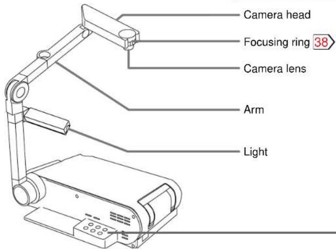
1 OVERLAY button 39
To activate the overlaying projection.
2 PHOTO/TEXT button 38
To switch modes between text and photo.
3 ARM LIGHT button 37
To turn on or off the light.
4 LOCK (W.BALANCE) indicator 38
Lights when the white balance is locked.
5 W.BALANCE button 38
To switch white balance settings between automatic adjustment and lock.
6 CAMERA button 37
To select the camera source.
Press again to return to the previous input source.
(Continued)
Camera
(Continued)
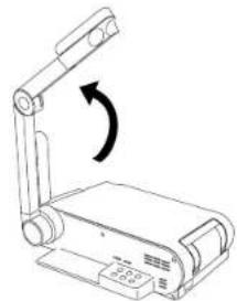
Preparation of the document imaging camera
1) Raise up the arm.

natural_image
Technical line drawing of a mechanical device with a scroll and directional arrow (no text or symbols)2) Stretch the arm.
natural_image
Diagram of a mechanical device with a rotating arm and base plate (no text or symbols)3) Turn the arm.

natural_image
Technical line drawing of a mechanical device with a lever and base plate (no text or symbols)4) Open the camera head.

natural_image
Line drawing of a mechanical device with an arm and base plate (no text or symbols)5) Turn the camera head.

natural_image
Line drawing of a mechanical device with an arm and base, showing no text or symbolsCONTENTS
6) Pull up the light.

natural_image
Line drawing of a mechanical device with a lever and base (no text or symbols)7) Turn the light.
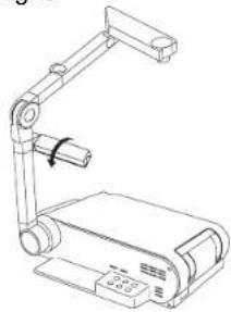
natural_image
Line drawing of a mechanical device with articulated arm and base (no text or symbols)Notes
- Never give shocks or impacts to the camera or arm as this may cause breakdowns.
- While raising up the arm in step 2), be careful not to hit your face or your body.
Camera
CONTENTS
Picture projection with the document imaging camera
Preparation
Display the image as explained in "Picture
Projection". 21


1 Press ARM LIGHT.
The light turns on.
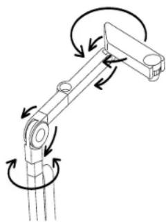
2 Place a document (text, illustration) onto or around the projector, and turn the camera head to direction of the document.

flowchart
graph TD
    A["LCD PROJECTOR"] --> B["Insert"]
    C["LCD PROJECTOR"] --> D["Insert"]
    E["LCD PROJECTOR"] --> F["Insert"]
    G["LCD PROJECTOR"] --> H["Insert"]
You can project around the projector by moving the arm and the camera head.
natural_image
Mechanical arm diagram showing rotational motion with arrows indicating clockwise rotation (no text or labels)3 Press CAMERA to select the camera input mode.
Pressing CAMERA on the camera control panel or INPUT on the main unit can also select it.
"Camera" is displayed.
4 Move the camera head to adjust the size of the picture.
Up : To reduce.

(Continued)
Camera
(Continued)
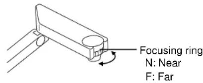
5 Focus on the picture by turning the focusing ring on the camera head.
6 Press PHOTO/TEXT to select the mode of the document.
PHOTO: when using a photograph.
TEXT: AB when using a text.
7 When finished, turn off the light and close it, and put back the arm.
Follow the steps of "Preparation of the document imaging camera" in reverse.
Note
The light turns off automatically when the arm is leaned.
CONTENTS
Locking the white balance
Normally, this camera automatically adjusts the color balance to project the picture. If the adjustment is not sufficient, follow the steps below to lock the white balance.
1) Project a white paper and enlarge it to fill the screen.
2) Press W.BALANCE to turn the LOCK indicator on.
The white balance is locked.
To release the white balance, press W.BALANCE again to turn the LOCK indicator off.
Notes
- When projecting a transparent draft such as an OHP film or a small size document such as a name card, etc., place the supplied pad under them.
- When the arm is not raised up, the camera source cannot be projected.
- If you raise up the arm while the camera input is selected, the color of the picture may vary for an instant due to the white balance adjustment. This is not malfunction.
- If you put back the arm and raise it up while the white balance is locked (the LOCK indicator is lit), the projector releases the white balance but leaves the LOCK indicator on. In this case, press W.BALANCE to restore the indicator to the normal status.
- "Camera gain" adjustment may improve view of a camera subject which is too dark or vivid.

Correcting illuminated defects
If there are some luminous dots on a projected picture, make the following correction.
1) While the camera is active, cover the camera lens with a black paper completely.
2) Press OVERLAY and ARM LIGHT at the same time.
Camera
Overlaying projection
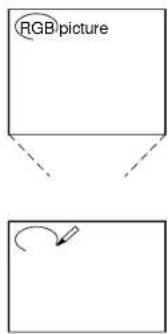
When an RGB source is projected, you can overlap your handwriting on it.
Preparation
• Display an RGB picture.
- Set the document imaging camera at the ready. 36

1 Prepare a white paper to write on.
2 Press OVERLAY.
The camera source is overlaid on the RGB picture.
3 Project the paper using the camera.
4 Write on the paper with a blue or red pen.
The handwriting is superimposed on the RGB picture.
flowchart
graph TD
    A["RGB picture"] --> B["Rotation Arrow Icon"]
Notes
- Handwriting in colors except blue and red cannot be displayed properly.
- Handwriting in fine lines may not be displayed properly.
CONTENTS
Maintenance
CONTENTS
Trouble indications
If there is some problem inside the projector, the indicators light up or flash.
ON Off or lit (red)
LAMP -
TEMP -
The power does not come on.
→ Malfunction of the unit.
- Unplug the power cord and call the dealer.
ON Lit (red)
LAMP Lit (red)
TEMP -
The lamp turns off or does not light up.
→ The lamp's end, or malfunction of the unit.
- Lamp's life length is over, replace the lamp with new one. 42
- Unplug the power cord and call the dealer.
ON Lit (red)
LAMP -
TEMP Lit (red)
The power turns off or does not come on.
→ The inside is too hot, or the projector has been working in an area of high temperature.
- Place the projector correctly so the intake and exhaust fans' holes are not covered.
- Turn the projector off, and leave it for a while, and turn it on again.
- Clean the air filter. 41
ON Lit (red)
LAMP -
TEMP Flashing (red)
The power turns off or does not come on.
→ Trouble with the intake fan.
- Unplug the power cord and call the dealer.
ON Lit (red)
LAMP -
TEMP Flashing (orange)
The power turns off or does not come on.
→ Trouble with the exhaust fan.
- Unplug the power cord and call the dealer.
Note
Before attempting any maintenance, unplug the power cord.
Maintenance
Air filter, lens and main unit cleaning
CAUTION
If you use the projector mounted on the ceiling, ask the dealer to carry out the maintenance such as cleaning.
Cleaning the air filter
The filter under the air filter cover is the device to shut out dusts or dregs.
Do not use the projector with the filter taken off. Give a frequent clean especially to the air filter. (The cleaning period is once per about 50 hours).
1) Unplug the power cord.
2) Take off the air filter cover.
The filter is on the right side of the projector. Pull up the filter tabs.

natural_image
Diagram of a mechanical device with a fan and rotating arrow (no text or symbols)3) Clean the air filter cover.
Remove dust and stains with a vacuum cleaner.
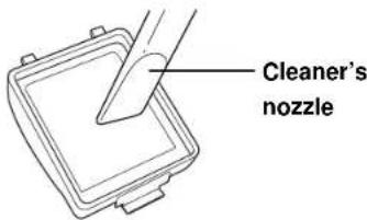
4) Attach the air filter cover.

natural_image
Line drawing of a car air conditioner unit with airflow direction indicator (no text or symbols)Notes
- When the air filter is dusty, the ventilation is impaired. This causes the temperature inside the projector to rise, and may damage the unit.
- Attach the air filter cover firmly after the cleaning. If it is not set correctly, the dusts will enter and they will be projected and overlapped on the picture.
CONTENTS
Cleaning the lens
Use a blower or a lens cleaner to clean the lens.
Never rub or tap the lens with a hard object as the lens surface is fragile.
Cleaning the main unit
• Pull out the power cord before cleaning.
- Use a soft cloth to wipe off stains from the surface.
• To remove difficult stains, use a soft cloth slightly moistened with a weak solution of synthetic detergent and water, and finish with a soft, dry cloth.
Replacing the intake, exhaust fans and air filter
To maintain the efficiency of the projector, replace the intake and exhaust fans about every two to three years.
Ask the dealer for the replacement.
Maintenance
Lamp replacement
The lamp will eventually begin to project dark or dull pictures and finally will not light up. (Lamp's life length depends on the use condition.) In such a case, replace the lamp with new one.
CAUTION
- If you use the projector mounted on the ceiling, ask the dealer to carry out the maintenance such as cleaning or replacement of the lamp.
- When replacing, always use lamp "TLPL6" (sold separately). For detail, refer to TLPL6 instruction.
- If you have been using the projector, the lamp will be very hot, and may cause burn injuries. Wait for the lamp to cool (for longer than 1 hour) before replacing it.
1 Unplug the power cord.
2 Wait until the lamp gets cold enough.
3 Take off the lamp cover on the bottom panel.
Loosen two screws, and pull off the lamp cover.

4 Pull out the lamp.
Loosen the two fixing screws, and lift up the handle to pull out the lamp.

5 Load a new lamp.
Slide until it hits the bottom and tighten the two fixed screws.

CONTENTS
6 Attach the lamp cover.
Slide the cover in place and tighten two screws.

7 Reset the lamp timer.
Refer to the lamp instructions for resetting.
Notes
- The projector displays the total working time at every 1,000 hours (only when plugged in and turned on; ex. “>1000H”, “>2000H”).
- The lamp should be replaced if the total working time exceeds about 2,000 hours.
- Attach the lamp cover firmly after replacing the lamp. If it is not set correctly, the power will not turn on.
- Use a new lamp when replacing it.
- The lamp is made of glass and is very fragile. Do not touch the lamp with your bare hands and do not jolt or damage it. Do not use an exhausted lamp.
Others
Before calling service personnel
Check the following points before asking for support service.
Refer also to "Trouble indications".40
The power does not come on.
- The power cord is disconnected.
→ Firmly plug in the power cord. 19
- The lamp cover is not attached correctly.
→ Attach the cover correctly. 42
The power turns off while using the projector.
- The ambient temperature of the projection room is too high.
→ Lower the ambient temperature of the projection room, and turn the power on.
No image appears.
- The lens cover is on.
→ Take off the lens cover.19
- The wrong input is selected.
→ Select the input source correctly. 21
• The muting mode is on.
→ Press MUTE to restore the picture. 23
- The "Brightness" adjustment is at its darkest.
→ Make the "Brightness" adjustment. 27
- The source is not correctly connected to the projector.
→ Connect the source correctly to the projector. 16
No sounds are heard.
• The wrong input is selected.
→ Select the input source correctly. 21
• The audio muting mode is on.
→ Press MUTE to restore the sound. 23
• The sound volume is at the minimum.
→ Adjust the sound volume on the menu. 33
- The source is not correctly connected to the projector.
→ Connect the source correctly to the projector. 16
The images are blurred. Focusing is uneven.
- The lens is dirty.
→ Clean the lens.
Use a lens cleaner to clean the lens. 41
CONTENTS
• The picture is out of focus.
→ Focus the picture. 21
- The projection distance is not appropriate.
→ Adjust the distance properly. 19
- The projecting light is not hitting the screen squarely.
→ Adjust the projecting direction so that the light hits the screen squarely. 19
- The "Brightness", "Contrast", "Sharpness" or "Phase" adjustments are not correct.
→ Make the "Image" or "Picture" adjustments. 31>32
The pictures are dim.
- The "Brightness" or "Contrast" adjustments are not correct.
→ Make the "Picture" adjustments. 32
• The lamp life is ending.
→ Replace the lamp. 42
The colors are faint. The colors are strange.
- The "Color", "Tint", "R-Level", "G-Level" or "B-Level" adjustments are not correct.
→ Make the "Picture" adjustments. 32
• The lamp life is ending.
→ Replace the lamp. 42
(Continued)
Others
(Continued)
Image does not appear when using the document imaging camera.
- The wrong input is selected. → Select the correct input source. 37
Image is out of focus or not clear when using the document imaging camera.
- The camera lens is dirty. → Clean the camera lens. Use a lens cleaner to clean the lens. 41
- The document imaging camera is out of focus. → Focus the document imaging camera. 38
- Focus between main unit and screen is not correct. → Focus the picture by turning the focusing ring. 21
- The light is not on. The image may not be projected clearly if the light is not on. → Turn on the light. 37
The remote control does not work.
• The remote control is not facing the remote sensor.
→ Face the remote control transmitter toward the remote sensor on the projector. 15
• The remote control is too far.
→ Operate within about 5 meters. 15
- There is an obstruction between the remote control and the remote sensor.
→ Remove the obstacle.
• The batteries are exhausted.
→ Replace the batteries. 14
- The operating mode of the remote control is not set correctly.
→ Set the POINTER/PJ selector according to the equipment you want to control. 13
CONTENTS
Input Signal
Mode determination and signal system
◎ : full compatible : dot resizing display
□: simplified display :●gh resolution serial transfer control
| Signal | Frequency | Synchronizing | Resol. Default (line) | Remarks | |||||
| Mode System | Horizontal (kHz) | Vertical (Hz) | Horizontal | Vertical H/V | 650/651 model | 450/451 model | |||
| NTSC | NTSC | 15.734 | 59.940 | 664 | 484 | N/N | ● | ● | VIDEO IN |
| PAL/SECAM | PAL/SECAM | 15.625 | 50.000 | 756 | 574 | N/N | ● | ● | VIDEO IN |
| NTSC/DTV480i | Digital broadcasting | 15.750 | 60.000 | 720/640 | 480 | N/N | ● | ● | RGB IN |
| DTV480P/VGA60Hz | Digital broadcasting | 31.500 | 60.000 | 720/640 | 480 | N/N | ○ | ○ | RGB IN |
| DTV720P | Digital broadcasting | 47.500 | 60.000 | 1280 | 720 | N/N | ○ | ○ | RGB IN |
| HDTV/DTV1080i | Hi-Vision/Digital broadcasting | 33.750 | 60.000 | 1920 | 1080 | N/N | ○ | ○ | RGB IN |
| NEC24K | PC98 Standard | 24.830 | 56.420 | 640 | 400 | N/N | ○ | ○ | RGB IN |
| TEXT70 | VGA-350 | 31.470 | 70.090 | 640 | 350 | P/N | ○ | ○ | RGB IN |
| TEXT70 | VGA-400 | 31.470 | 70.090 | 640 | 400 | N/P | ○ | ○ | RGB IN |
| TEXT85 | VGA 85Hz-1 | 37.861 | 85.080 | 640 | 350 | P/N | ○ | ○ | RGB IN |
| TEXT85 | VGA 85Hz-2 | 37.861 | 85.080 | 640 | 400 | N/P | ○ | ○ | RGB IN |
| VGA60 | VGA 60Hz | 31.470 | 59.940 | 640 | 480 | N/N | ○ | ○ | RGB IN |
| VGA72 | VGA 72Hz | 37.861 | 72.809 | 640 | 480 | N/N | ○ | ○ | RGB IN |
| VGA75 | VGA 75Hz | 37.500 | 75.000 | 640 | 480 | N/N | ○ | ○ | RGB IN |
| VGA85 | VGA 85Hz-4 | 43.269 | 85.008 | 640 | 480 | N/N | ○ | ○ | RGB IN |
| MAC13 | MAC-13" | 35.000 | 66.667 | 640 | 480 | -/- | ○ | ○ | RGB IN |
| SVGA56 | SVGA 56Hz | 35.156 | 56.250 | 800 | 600 | P/P | ○ | ○ | RGB IN |
| SVGA60 | SVGA 60Hz | 37.879 | 60.317 | 800 | 600 | P/P | ○ | ○ | RGB IN |
| SVGA72 | SVGA 72Hz | 48.077 | 72.188 | 800 | 600 | P/P | ○ | ○ | RGB IN |
| SVGA75 | SVGA 75Hz | 46.875 | 75.000 | 800 | 600 | P/P | ○ | ○ | RGB IN |
| SVGA85 | SVGA 85Hz | 53.674 | 85.061 | 800 | 600 | P/P | ○ | ○ | RGB IN |
| MAC16 | MAC-16" | 49.724 | 74.550 | 832 | 624 | -/- | ○ | ○ | RGB IN |
| XGA43i | XGA 43Hz interlace | 35.522 | 43.479x2 | 1024 | 768 | P/P | ○ | ○ | RGB IN |
Others
(Continued)
CONTENTS
◎ : full compatible : dot resizing display
□: simplified display :●gh resolution serial transfer control
| Signal | Frequency | Synchronizing | Resol. | Defaultline) | Remarks | ||||
| Mode System | Horizontal (kHz) | Vertical (Hz) | Horizontal | Vertical H/V | 650/651 model | 450/451 model | |||
| XGA60 | XGA 60Hz | 48.363 | 60.004 | 1024 | 768 | N/N | ◎ | ○ | RGB IN |
| XGA70 | XGA 70Hz | 56.476 | 70.069 | 1024 | 768 | N/N | ◎ | ○ | RGB IN |
| XGA75 | XGA 75Hz | 60.023 | 75.029 | 1024 | 768 | P/P | ◎ | ○ | RGB IN |
| XGA85 | XGA 85Hz | 68.677 | 84.997 | 1024 | 768 | N/N | ◎ | ○ | RGB IN |
| MAC19 | MAC-19" | 60.197 | 74.872 | 1024 | 768 | N/N | ◎ | ○ | RGB IN |
| SXGA75-1 | SXGA 75Hz | 67.500 | 75.000 | 1152 | 864 | P/P | ○ | ○ | RGB IN |
| MAC21 | MAC-21" | 68.681 | 75.062 | 1152 | 870 | -/- | ○ | ○ | RGB IN |
| SXGA60-1 | SXGA 60Hz | 60.000 | 60.000 | 1280 | 960 | P/P | ○ | ○ | RGB IN |
| SXGA85-1 | SXGA 85Hz | 85.938 | 85.002 | 1280 | 960 | P/P | □ | □ | RGB IN |
| SXGA43i | SXGA 43Hz interlace | 46.433 | 43.436x2 | 1280 | 1024 | P/P | ○ | ○ | RGB IN |
| SXGA60-2 | SXGA 60Hz | 63.981 | 60.020 | 1280 | 1024 | P/P | ○ | ○ | RGB IN |
| SXGA75-2 | SXGA 75Hz | 79.976 | 75.025 | 1280 | 1024 | P/P | ○ | ○ | RGB IN |
| SXGA85-2 | SXGA 85Hz | 91.146 | 85.024 | 1280 | 1024 | P/P | □ | □ | RGB IN |
| UXGA60 | UXGA 60Hz | 75.000 | 60.000 | 1600 | 1200 | P/P | □ | □ | RGB IN |
| UXGA65 | UXGA 65Hz | 81.130 | 65.000 | 1600 | 1200 | P/P | □ | □ | RGB IN |
| UXGA70 | UXGA 70Hz | 87.500 | 70.000 | 1600 | 1200 | P/P | □ | □ | RGB IN |
| UXGA75 | UXGA 75Hz | 93.750 | 75.000 | 1600 | 1200 | P/P | □ | □ | RGB IN |
Notes
- If the mode identification does not define the mode described on the chart above, adjust to the projection details.
- If the mode identification is carried out correctly, a normal display may be not obtained depending on the signal frequency.
- SXGA, UXGA signals can be projected since the projector has simplified compatibility with them. (However, letters and lines can be unequal or a part can be missing. Some signals may not be projected at all.)
- Some computers may have output modes which are not compatible with this projector. Check the compatibility of the connectors, signal levels, timing, and resolutions.
(Continued)
Others
(Continued)
CONTENTS
Signal assignment

D-SUB 15 pin shrinking terminal
Input Signal
Video signal
Analog 0.7V(p-p) 75Ω
Horizontal synchronizing signal
TTL level (positive/negative polarity)
Vertical synchronizing signal
TTL level (positive/negative polarity)
Composite synchronizing signal
TTL level
Pin arrangements
| Pin No. | |
| 1 | Video input (Red) |
| 2 | Video input (Green) |
| 3 | Video input (Blue) |
| 4 | N.C |
| 5 | GND |
| 6 | GND (Red) |
| 7 | GND (Green) |
| 8 | GND (Blue) |
| 9 | N.C |
| 10 | GND |
| 11 | GND |
| 12 | N.C |
| 13 | Horizontal synchronizing/composite synchronizing signal |
| 14 | Vertical synchronizing signal |
| 15 | N.C |
(Continued)
RGB signal defaults
The following signals are factory set as defaults in each mode. However, some computers may have different timings than those in the chart. Make the necessary adjustments if the picture has flickers or is blurred.
Video Timing (Horizontal)

Video Timing (Vertical)
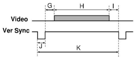
Timing chart
| Mode Resolution | A (Pixels) | B (Pixels) | C (Pixels) | D (Pixels) | E (Pixels) | fh (kHz) | fv (Hz) | Clock (MHz) | G (Lines) | H (Lines) | I (Lines) | J (Lines) | K (Lines) | |
| NEC24k | 640 x 400 | 85 | 640 | 59 | 64 | 848 | 24.83 | 56.42 | 21.053 | 25 | 400 | 7 | 8 | 440 |
| TEXT70 | 640 x 350 | 50 | 640 | 14 | 96 | 800 | 31.47 | 70.09 | 25.175 | 59 | 350 | 38 | 2 | 449 |
| TEXT70 | 640 x 400 | 50 | 640 | 14 | 96 | 800 | 31.47 | 70.09 | 25.175 | 34 | 400 | 13 | 2 | 449 |
| TEXT85 | 640 x 350 | 96 | 640 | 32 | 64 | 832 | 37.86 | 85.08 | 31.500 | 60 | 350 | 32 | 3 | 445 |
| TEXT85 | 640 x 400 | 96 | 640 | 32 | 64 | 832 | 37.86 | 85.08 | 31.500 | 41 | 400 | 1 | 3 | 445 |
| VGA60 | 640 x 480 | 48 | 640 | 16 | 96 | 800 | 31.47 | 59.94 | 25.175 | 33 | 480 | 10 | 2 | 525 |
| VGA72 | 640 x 480 | 128 | 640 | 24 | 40 | 832 | 37.86 | 72.81 | 31.500 | 28 | 480 | 9 | 3 | 520 |
| VGA75 | 640 x 480 | 120 | 640 | 16 | 64 | 840 | 37.50 | 75.00 | 31.500 | 16 | 480 | 1 | 3 | 500 |
| VGA85 | 640 x 480 | 80 | 640 | 56 | 56 | 832 | 43.27 | 85.01 | 36.000 | 25 | 480 | 1 | 3 | 509 |
| MAC13 | 640 x 480 | 96 | 640 | 64 | 64 | 864 | 35.00 | 66.67 | 30.240 | 39 | 480 | 3 | 3 | 525 |
| SVGA56 | 800 x 600 | 128 | 800 | 24 | 72 | 1024 | 35.16 | 56.25 | 36.000 | 22 | 600 | 1 | 2 | 625 |
| SVGA60 | 800 x 600 | 88 | 800 | 40 | 128 | 1056 | 37.88 | 60.32 | 40.000 | 23 | 600 | 1 | 4 | 628 |
| SVGA72 | 800 x 600 | 64 | 800 | 56 | 120 | 1040 | 48.08 | 72.19 | 50.000 | 23 | 600 | 37 | 6 | 666 |
| SVGA75 | 800 x 600 | 160 | 800 | 16 | 80 | 1056 | 46.88 | 75.00 | 49.500 | 21 | 600 | 1 | 3 | 625 |
| SVGA85 | 800 x 600 | 152 | 800 | 32 | 64 | 1048 | 53.67 | 85.06 | 56.250 | 27 | 600 | 1 | 3 | 631 |
| MAC16 | 823 x 624 | 216 | 832 | 40 | 64 | 1152 | 49.72 | 74.55 | 57.283 | 39 | 632 | 1 | 3 | 667 |
| XGA60 | 1024 x 768 | 160 | 1024 | 24 | 136 | 1344 | 48.363 | 60.004 | 65.000 | 29 | 768 | 3 | 6 | 806 |
| XGA70 | 1024 x 768 | 144 | 1024 | 24 | 136 | 1328 | 56.476 | 70.069 | 75.000 | 29 | 768 | 3 | 6 | 806 |
| XGA75 | 1024 x 768 | 176 | 1024 | 16 | 96 | 1312 | 60.023 | 75.029 | 78.750 | 28 | 768 | 1 | 3 | 800 |
| XGA85 | 1024 x 768 | 208 | 1024 | 48 | 96 | 1376 | 68.677 | 84.997 | 94.500 | 36 | 768 | 1 | 3 | 808 |
| MAC19 | 1024 x 768 | 180 | 1024 | 20 | 96 | 1320 | 60.197 | 74.872 | 73.200 | 30 | 768 | 3 | 3 | 804 |
Adjustments with RS-232C
Conditioning of the Projection Unit can also be done by a computer via the RS-232C, as well as by the remote control.

Mini DIN 8-pin
(Main Unit)
| Pin No. | Signal | Meaning |
| 1 | N.C | No connection |
| 2 | TXD | Sending data |
| 3 | RXD | Receiving data |
| 4 | DSR | Data set ready |
| 5 | GND | Signal ground |
| 6 | DTR | Data terminal ready |
| 7 | CTS | Consent to send |
| 8 | RTS | Request to send |
Interface format
1 Communication RS-232C
method No parity + 8DATA + 1 STOP bit
2 Data format Command shall be composed of
alphanumeric characters of ASCII
description. Use only capital letters.
3 Speed 9600 bps
4 Communication STX (02h) Command (3Byte) ETX (03h)
format
5 Return value One command only can be used in one
communication.
Acknowledge ACK (06h)
Not Acknowledge NAK (15h)
Command list
| Classification | Command | Meaning |
| NORMAL | POF | Power OFF |
| NORMAL | PON | Power ON |
| NORMAL | MOF | Video audio mute OFF |
| NORMAL | MON | Video audio mute ON |
| NORMAL | AOF | Audio mute OFF |
| NORMAL | AON | Audio mute ON |
| NORMAL | DOF | Status display OFF |
| NORMAL | DON | Status display ON |
| NORMAL | FOF | Freeze OFF |
| NORMAL | FON | Freeze ON |
| NORMAL | IN1 | Input (RGB) |
| NORMAL | IN2 | Input (Video) |
| NORMAL | IN3 | Input (Camera) |
| RESIZE | RS0 | Resize reset |
| RESIZE | RS1 | Resize 1 |
| RESIZE | RS2 | Resize 2 |
| RESIZE | RS3 | Resize 3 |
| RESIZE | RS4 | Resize 4 |
| RESIZE | PO0 | Position reset |
| RESIZE | PO1 | Position upper shift |
| RESIZE | PO2 | Position lower shift |
| RESIZE | PO3 | Position left shift |
| RESIZE | PO4 | Position right shift |
| CAMERA | CW0 | Automatic W/B OFF |
| CAMERA | CW1 | Automatic W/B ON |
| CAMERA | CS0 | Text mode OFF |
| CAMERA | CS1 | Text mode ON |
| CAMERA | CO0 | Overlaying mode OFF |
| CAMERA | CO1 | Overlaying mode ON |
| ADJUST | ARS | Adjustment value reset |
| ADJUST | ARG | Adjustment value increase |
(Continued)
Others
(Continued)
CONTENTS
| Classification | Command | Meaning |
| ADJUST | ALF | Adjustment value decrease |
| ADJUST | AUP | Adjustment value increase |
| ADJUST | ADW | Adjustment value decrease |
| KEYSTONE | PKA | Keystone automatic adjustment |
| KEYSTONE | PKS | Keystone manual adjustment |
| Image | PAT | Panel automatic adjustment |
| Image | PVP | Vertical position adjustment |
| Image | PHP | Horizontal position adjustment |
| Image | PPH | Phase adjustment |
| Image | PCK | Clock adjustment |
| Picture | VBR | Brightness adjustment |
| Picture | VCL | Color adjustment |
| Picture | VCN | Contrast adjustment |
| Picture | VSH | Sharp adjustment |
| Picture | VTN | Tint adjustment |
| Picture | VLB | Blue level adjustment |
| Picture | VLG | Green level adjustment |
| Picture | VLR | Red level adjustment |
| Picture | CGN | Camera gain adjustment |
| Audio | VOL | Volume adjustment |
| Audio | VTR | Treble adjustment |
| Audio | VBS | Bass adjustment |
| Default | LJP | Japanese display setting |
| Default | LEN | English display setting |
| Default | LFR | French display setting |
| Classification | Command | Meaning |
| Default | LGR | German display setting |
| Default | LIT | Italian display setting |
| Default | LSP | Spanish display setting |
| Default | LP0 | Portuguese display setting |
| Default | PJ0 | Floor-mounted front projection |
| Default | PJ1 | Floor-mounted rear projection |
| Default | PJ2 | Ceiling-mounted front projection |
| Default | PJ3 | Ceiling-mounted rear projection |
| Default | KR0 | RGB input mode (RGB) |
| Default | KR1 | RGB input mode (Y/Pb/Pr) |
| Default | KV0 | Video signal mode (Automatic) |
| Default | KV1 | Video signal mode (60/NTSC/JAPAN) |
| Default | KV2 | Video signal mode (60/NTSC/3.58) |
| Default | KV3 | Video signal mode (60/NTSC/4.43) |
| Default | KV4 | Video signal mode (60/PAL/3.58) |
| Default | KV5 | Video signal mode (60/PAL/4.43) |
| Default | KV6 | Video signal mode (50/NTSC/3.58) |
| Default | KV7 | Video signal mode (50/NTSC/4.43) |
| Default | KV8 | Video signal mode (50/PAL/3.58) |
| Default | KV9 | Video signal mode (50/PAL/4.43) |
| Default | KVA | Video signal mode (50/SECAM/4.43) |
| Default | MO0 | OSD mute OFF |
| Default | MO1 | OSD mute ON |
| Save | DRS | Adjustment value preset |
| Save | DSV | Adjustment value saving |
Others
Specifications
Main unit
Power requirements
AC 100 - 240V 50/60Hz
Power consumption
TLP450E, TXP450 : 220W
TLP451E, TXP451 : 235W
TLP650E, TXP650 : 220W
TLP651E, TXP651 : 235W
Mass TLP450E, TXP450 : 3.7 Kg
TLP451E, TXP451 : 4.5 Kg
TLP650E, TXP650 : 3.7 Kg
TLP651E, TXP651 : 4.5 Kg
Dimensions
TLP450E, TLP650E, TXP450, TXP650 :
318 x 87 x 232 (mm) (W/H/D)
(Including the projecting sections)
TLP451E, TLP651E, TXP451, TXP651 :
318 x 87 x 288 (mm) (W/H/D)
(Including the projecting sections)
Ambient environment
Temperature : 0°C to 35°C
Humidity : 30% to 70% RH
Lamp UHP lamp 150W
Speaker 1W (monaural)
RGB INPUT
RGB signal : (D-sub 15-pin)
Audio: 1V(p-p), more than 22kΩ,
Audio : 1V(p-p), more than 22kΩ,
RCA pin jack
MONITOR OUTPUT
RGB signal : D-sub 15-pin
Audio : 1V(p-p), less than 2.2kΩ,
3-pannels transmission
Panel size
0.9 inches
Driving system
TFT active matrix
Picture elements
TLP450E, TLP451E, TXP450, TXP451 :
480,000 pixels (800 x 600 dots) x 3
TLP650E, TLP651E, TXP650, TXP651 :
786,432 pixels (1024 x 768 dots) x 3
CONTENTS
Projection lens
Lens Zooming lens F = 1.8 - 2.1
f = 36 - 47mm
Focusing Manual operation
Zooming Manual operation
Document imaging camera
Lens F = 1.8 - 2.3, f = 5.8 - 23.2mm
Focus Manual operation
Iris Auto/Level adjustment allowed
Image element
1/3 inch CCD
Total picture elements
810,000 pixels
Resolution Horizontal 1024, vertical 768
Lighting LED light
(Continued)
Others
(Continued)
Accessories
Wireless remote control 1
AA size battery 2
Power cord 2
RGB cable....1 (3m)
Adapter for Macintosh computers .... 1
PC audio cable....1 (3m)
Audio/Video cable 1 (3m)
Lens cover.... 1
REMOTE MOUSE RECEIVER .... 1
IBM/MAC mouse cable
(for REMOTE MOUSE RECEIVER)...... 1
PS/2 mouse adapter
(for REMOTE MOUSE RECEIVER)...... 1
MAC mouse adapter
(for REMOTE MOUSE RECEIVER)...... 1
USB mouse cable
(for REMOTE MOUSE RECEIVER)...... 1
Pointing rod 1
Carrying case 1
The design and specifications are subject to change without notice.
CONTENTS
Trademarks
NEC, PC-98 series are trademarks of NEC Corporation.
IBM, DOS/V, VGA, SVGA, XGA, SXGA, UXGA are trademarks or registered trademarks of International Business Machines Corporation.
Macintosh is a registered trademark of Apple Computer, Inc.
Windows is a registered trademark of Microsoft Corporations in the U.S. and other countries.
TOSHIBA CORPORATION
- IMPORTANT PRECAUTIONS
- Save Original Packing Materials
- Avoid Volatile Liquid
- Moisture Condensation
- IMPORTANT SAFETY INSTRUCTIONS
- Read Owner's Manual
- Power Sources
- Source of Light
- Ventilation
- Heat
- Cleaning
- Overloading
- Water and Moisture
- Power-Cord Protection
- Lightning
- Object and Liquid Entry
- Do not place the product vertically
- Stack Inhibited
- Attachments
- Accessories
- Damage Requiring Service
- Servicing
- Replacement Parts
- Safety Check
- Do not get your hands between the camera arm and the main unit when setting the camera arm back in its original position.
- Do not carry by the camera arm.
- Do not leave documents on the unit for long periods of time while using the document imaging function.
- Do not move the projector while the arm is still erect.
- Before use
- Power supply cord selection
- Contents
- Connections and installation
- Operations
- Adjustments
- Camera
- Maintenance
- Others
- Part names and functions
- Main unit
- Left side Right side
- Rear side
- Remote control
- (Continued)
- Installing batteries
- Notes
- Remote control operation
- Connections
- Connecting an IBM PC or compatible computer (DOS/V)
- Connecting a Macintosh computer
- Connecting video equipment
- Note
- Output terminals
- Projector placement
- CAUTION
- Preparation
- Floor-mounted front projection
- Floor-mounted rear projection
- Ceiling-mounted front projection
- Ceiling-mounted rear projection
- Place the projector on a steady, level surface such as a table.
- Adjust the distance between the lens and the screen.
- Connect the power cord.
- Take off the lens cover.
- How to use the foot adjuster
- Picture projection
- Press ON/STANDBY.
- Turn on the connected equipment and put it in playback mode.
- Select the input source.
- Adjust the picture size by turning the zooming ring.
- Focus on the picture by turning the focusing ring.
- Turning the power off
- Correcting the keystone distortion
- Press KEYSTONE.
- Adjusting the image automatically
- Cutting off the picture and sound temporarily
- Freezing the picture
- Displaying the input source information
- Changing the picture size
- Operating the computer by the remote control
- Connecting the REMOTE MOUSE RECEIVER
- Settings and adjustments on the menu
- Keystone
- Image
- Picture
- Audio
- Default
- Save
- Initial settings
- - Default
- Press MENU to display the menu.
- Press ◀ or ▶ to select
- Press ▲ or ▼ to select a preferred item.
- Press ◀ or ▶ to make the setting.
- RGB input
- Video signal
- Press MENU.
- Keystone correction - Keystone
- Projection adjustments - Image
- Picture adjustments – Picture
- Press
- Press ◀ or ▶ to adjust the item.
- Sound adjustments – Audio
- Press ▲or ▼o select a preferred item.
- Saving data - Save
- Part names and functions of document imaging camera
- Preparation of the document imaging camera
- Picture projection with the document imaging camera
- Press ARM LIGHT.
- Place a document (text, illustration) onto or around the projector, and turn the camera head to direction of the document.
- Press CAMERA to select the camera input mode.
- Move the camera head to adjust the size of the picture.
- Focus on the picture by turning the focusing ring on the camera head.
- Press PHOTO/TEXT to select the mode of the document.
- When finished, turn off the light and close it, and put back the arm.
- Locking the white balance
- Correcting illuminated defects
- Overlaying projection
- Trouble indications
- Air filter, lens and main unit cleaning
- Cleaning the air filter
- Cleaning the lens
- Cleaning the main unit
- Replacing the intake, exhaust fans and air filter
- Lamp replacement
- Before calling service personnel
- Input Signal
- Mode determination and signal system
- RGB signal defaults
- Adjustments with RS-232C
- Interface format
- Command list
- Specifications
- Projection lens
- Document imaging camera
- Accessories
Brand : TOSHIBA
Model : TXP-650
Category : Video projector