
SKDP03-T - Unspecified AXIS - Free user manual and instructions
Find the device manual for free SKDP03-T AXIS in PDF.

| Product Type | Cable Kit |
| Brand | AXIS |
| Model | SKDP03-T |
| Cable Length | 95 m |
| Voltage | 24 VDC |
| Connector Type | RJ45 (CAT6) |
| Shielding | Yes (braided shield with blank shielding wire) |
| Application | Hazardous areas (Ex-d, Ex-e) |
| Kit Contents | 95 m system cable, cable gland with compound, 5 ml Loctite threadlock, CAT6 RJ45 plug (5.5–10.5 mm), 40 cm yellow-green shrink tube, 10 cm black shrink tube, 8 wire-end ferrules, documentation |
| Cable Cross-section | 4 twisted pairs, 3 power cores, ground |
| Mounting | ExTB-3 terminal box and Ex-d barrier gland |
| Safety | Qualified personnel only; observe IEC 60079-14 and national regulations |
| Support | Email: support@samcon.eu, Tel: +49 6426 9231-0 |
Frequently Asked Questions - SKDP03-T AXIS
User questions about SKDP03-T AXIS
0 question about this device. Answer the ones you know or ask your own.
Ask a new question about this device
Download the instructions for your Unspecified in PDF format for free! Find your manual SKDP03-T - AXIS and take your electronic device back in hand. On this page are published all the documents necessary for the use of your device. SKDP03-T by AXIS.
USER MANUAL SKDP03-T AXIS
Mounting instructions

SAMCON
1 Content of the Cable Kit SKDP03-T 3
2 Installing and wiring (connection to ExTB-3)....3
2.1 Customization of the cable connection....4
2.2 Insertion into Ex-e 6
2.3 Connecting the cable to the clamps 6
3 Mounting the barrier gland (insertion into Ex-d)....7
3.1 Components of the barrier gland....7
3.2 Configuration of the connection....7
3.3 Kneading....8
3.4 Adhesive bonding (Loctite) 8
4 Connecting the RJ 45 plug (Ex-d or non-ex)....9
5 Connecting the power channel (24VDC)....10
6 Support / contact....10
7 Notes 11
Table of Figures
Figure 1.1 – Content of the Cable Kit SKDP03-T ....3
Figure 2.1 – Cable cross section ....4
Figure 2.2 – Stripped cable and bare shielding ....4
Figure 2.3 – Blank shielding wire and shielding braid....4
Figure 2.4 – Shrinking tube over twisted shielding braid ....5
Figure 2.5 – Customized cable....5
Figure 2.6 – Connection in the terminal box ....6
Figure 3.1 – Components of the barrier gland ....7
Figure 3.2 – Configure the connection for the barrier gland ....7
Figure 3.3 – Kneading of the barrier gland ....8
Figure 3.4 – Glued-areas....8
Figure 4.1 – Connecting the RJ 45 plug ....9
Figure 4.2 – Completed cable with a RJ 45 plug....9
Revision history
Product: Cable Kit SKDP03-T 95 M
Title: Cable Kit SKDP03-T 95 M Mounting instructions
Doc. -Id. CableKitSKDP03-T_95M_MountingInstructions_rev.00.docx
Autor: Eva Schneider
Datum: May 9, 2018
| Rev.- Index | Datum | Name | Comment | Approved by EX Officer |
| 0 | May 9th, 2018 | E.Schneider | Compilation of the document |
1 Content of the Cable Kit SKDP03-T
natural_image
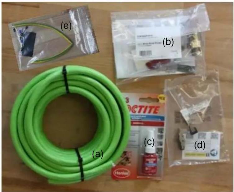
Assorted items including a green hose, plastic bags, and packaged products on a wooden surface (no visible text or symbols)Figure 1.1 – Content of the Cable Kit SKDP03-T
√ 95 m SKDP03-T System Cable Digital (a)
√ 1 x cable gland with compound (b)
√ 5 ml Loctite threadlock (c)
√ 1 x CAT6 RJ45 industrial plug pro (5.5 – 10.5 mm) (d)
√ 40 cm shrinking tube yellow-green (e)
√ 10 cm shrinking tube black (e)
√ 8 x wire-end ferrules (e)
√ 1 x documentation
2 Installing and wiring (connection to ExTB-3)
The following chapter describes the configuration of the cable, how to insert it into the terminal box ExTB-3 and how to connect it.

Attention!
The electrical connection of the equipment must be executed by qualified personnel only!

Attention!
Please observe the national regulations regarding security, installation, and accident prevention (e.g. IEC 60079-14)!

Attention!
When stripping the isolation, no inner cores must be damaged!
2.1 Customization of the cable connection
Looking at the digital system cable's cross section, the following elements are visible:
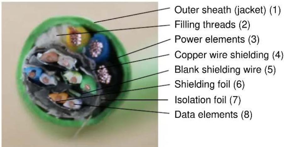
Figure 2.1 – Cable cross section
Remove 10 cm of the wire's outer sheath (green jacket) (1) without damaging the wires. Then cut off the white filling threads (2) and remove the white foil around the network cables (7) so that the shield is uncovered. In a next step, separate the shield by pulling out the data elements (8) from the copper wire shielding (4) (see figure 2.2).
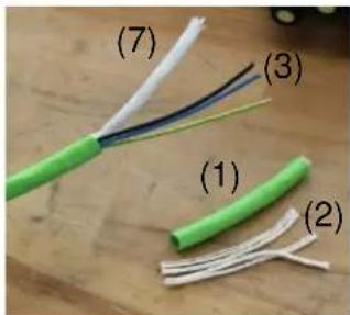
natural_image
Close-up of a green cable with exposed wire and a damaged metallic clip, alongside a blue and yellow cable (no text or symbols visible)Figure 2.2 - Stripped cable and bare shielding
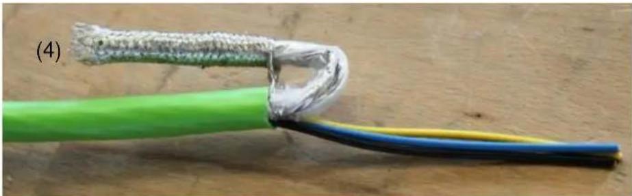
Cut off the five filling threads and the plastic foil. Make sure that the blank shielding wire (5) is not removed. Twist this blank wire with the shielding (4) as shown below.
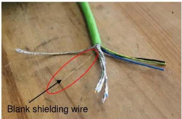
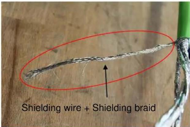
Figure 2.3 – Blank shielding wire and shielding braid
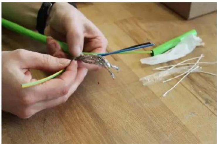
Cut the yellow-green shrinking tube to match the length of the shielding braid. Now shrink-fit the shrinking tube by using a hot air blower.
natural_image
Close-up of hands assembling a small green and white plastic component on a wooden surface (no text or symbols visible)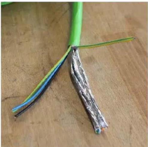
natural_image
Close-up of a green cable with exposed black, blue, and silver insulation against a wooden surface (no text or symbols)Figure 2.4 – Shrinking tube over twisted shielding braid
After this, put the black shrinking tube over all cables and the shielding and shrink it. Remove approx. 1 cm of the foil (6) at the top of the 4 twisted pairs (8). Untwist them to match this length and cut off the ends with a wire stripper. Squeeze the wire end ferrules onto the 3 power cables the grounding cable.
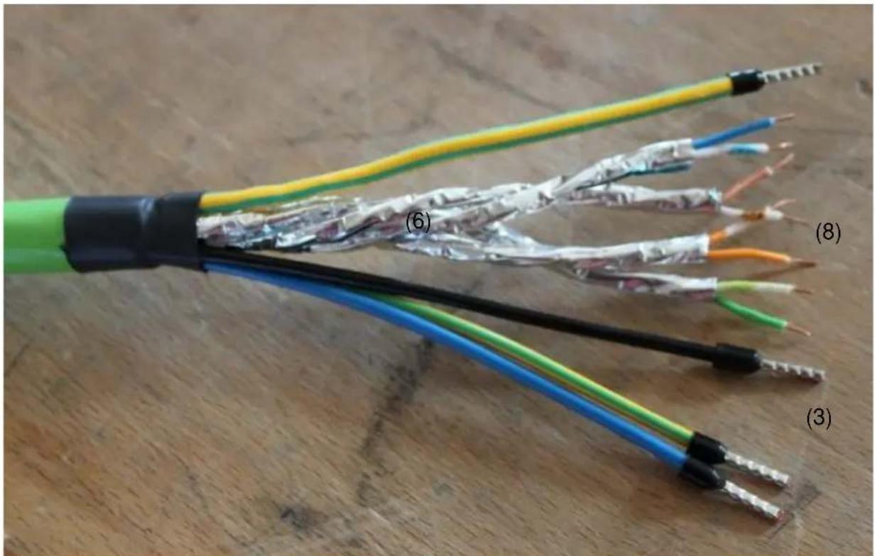
natural_image
Close-up of a multi-core electrical cable with exposed wires and insulation, labeled (3) to (8), showing color-coded bands and connectors.Figure 2.5 – Customized cable
2.2 Insertion into Ex-e
Through the middle cable gland, insert the prepared cable (q.v. chapter 2.1) into the terminal box ExTB3.
2.3 Connecting the cable to the clamps
Corresponding to the color code of the already connected camera cable, also the cables of the cable kit are connected so that the colors match. Please do not untie the twisted pair network and put the shielding braid as close to the clamps as possible. Tidily strip the ends of the wires and mount them firmly.
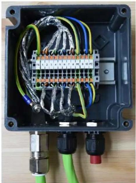
natural_image
Interior view of an electrical enclosure with wiring and connectors (no visible text or symbols)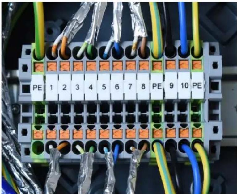
natural_image
Electrical terminal block with orange connectors and multicolored wires, no visible text or symbolsFigure 2.6 - Connection in the terminal box
On YouTube, you will find precise instructions on the cable configuration and the connection inside the terminal box ExTB3 at: https://www.youtube.com/watch?v=lqd5fsS7MsM

3 Mounting the barrier gland (insertion into Ex-d)
3.1 Components of the barrier gland
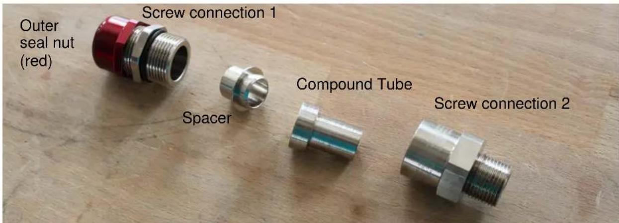
Figure 3.1 – Components of the barrier gland
3.2 Configuration of the connection
Strip 25 cm off the green jacket (q.v. chapter 2.1, figure 2.1 (1)) and cut off the isolation foil (7). Please make sure not to damage the individual wires of the connecting cable. Cut off the white filling threads (2) and remove the foil around the network cables (6). Then separate the shield and cut off the blank shielding wire (5) and the shielding braid (4) so that the foil around the cables can be removed. To prepare the twisted pairs (8) for the kneading screw connection, they need to be untwisted.
Slightly unscrew the red outer seal nut until the cable can be easily inserted into the screw connection 1 (insert direction: from outer seal nut towards screw connection 1). The rim of the green sheath must close flush with the screw connection 1. Then tighten the red outer seal nut enough to hold the cable in position and put the spacer on top.
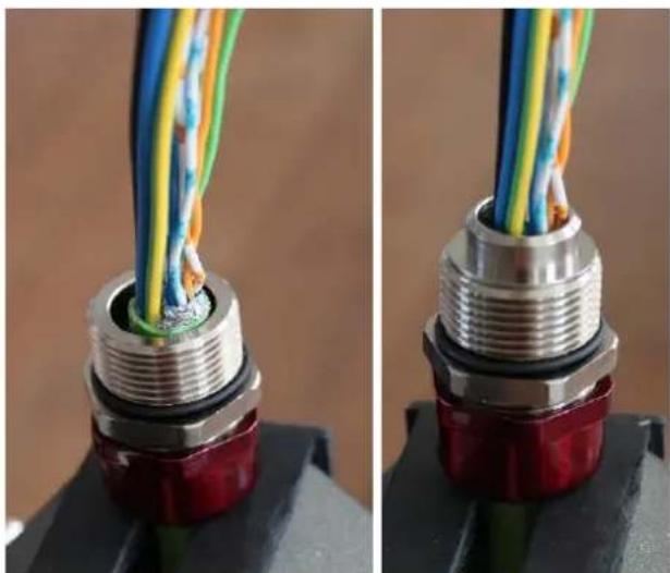
natural_image
Close-up of two identical electronic connectors with multicolored wires inserted into a red and black base (no text or symbols visible)Figure 3.2 - Configure the connection for the barrier gland
3.3 Kneading
Put on the supplied protective gloves and mix both components of the two-part epoxy compound until it is pliable and of an even color (minimum mixing temperature 10^ C / 50^ F). Untwist the cable cores and apply the compound around them over a length of 40 mm so that there is compound around each individual cable core (zigzag). Now put the compound tube over the cable and pass the compound tube over the conductors until the stepped end is fully located with the tube spacer. Remove surplus compound and make sure that it does not overlap the tube. If required, add more compound into place until the compound tube is fully filled.
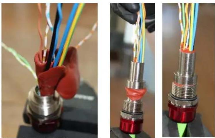
Figure 3.3 – Kneading of the barrier gland
The compound should be flush to the tube. Please let everything dry for at least 24 h and allow the compound to harden. After the drying period, please check that all cables are tightly connected with the compound and screw on the screw connection 2 until it comes to an effective stop.
3.4 Adhesive bonding (Loctite)
Please apply threadlocker (Loctite) generously to all three threads of the barrier gland). The Loctite is included in the delivery scope.
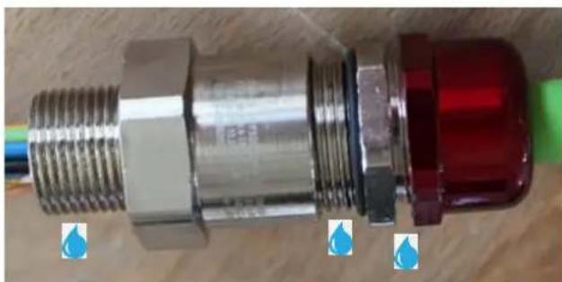
natural_image
Close-up of a metallic connector with threaded shaft and red cap, placed on a wooden surface with blue droplets (no text or symbols visible)Figure 3.4 – Glued-areas

For more detailed instructions on how to set up the barrier gland (insertion into Ex-d) please refer to our YouTube tutorial: https://www.youtube.com/watch?v=U1nap29TEFY
4 Connecting the RJ 45 plug (Ex-d or non-ex)
Strip off 25 cm of the cable isolation as described in chapter 3.1. Please make sure not to damage the isolation foil (7).
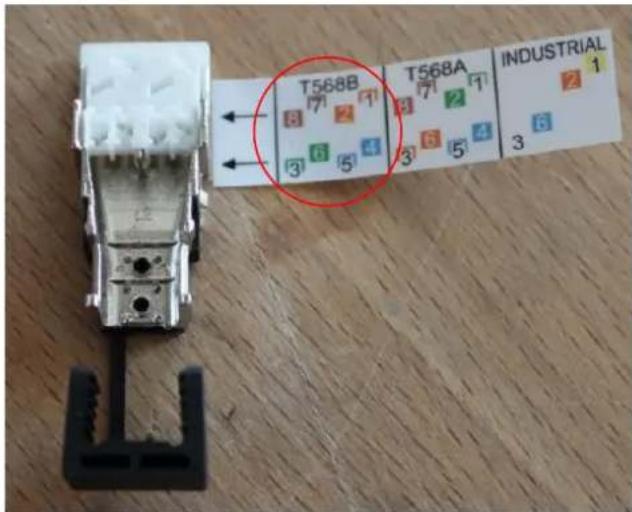
The plug is connected according to EIA/TIA-568B (q.v. attached sketch).
The cables of the same color will be put through the applicable opening and then cut off flush at the front. It is important that the shielding is lead through until it touches the shielding clamp.
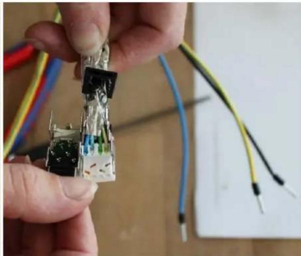
natural_image
Close-up of hands holding a small electronic component with wires and connectors (no visible text or symbols)Figure 4.1 - Connecting the RJ 45 plug
With a gripper, press together the plug until it snaps and remove the piece of paper.
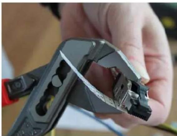
natural_image
Close-up of a hand holding a metal wire crimping tool, showing internal components and a hole (no text or symbols visible)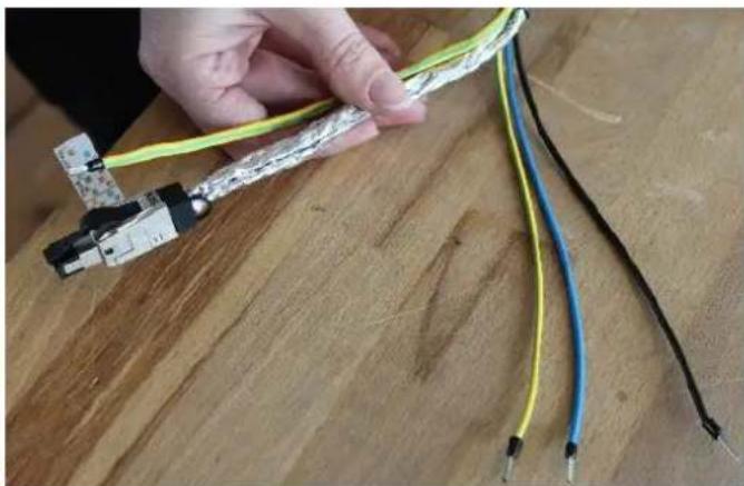
natural_image
Hand holding a flexible electrical cable with black, blue, and yellow wires against a wooden surface (no text or symbols visible)Figure 4.2 - Completed cable with a RJ 45 plug
For detailed instructions regarding the connection of the RJ 45 plug please refer to our YouTube tutorial: https://www.youtube.com/watch?v=LOJ_7drrn4E&feature=youtu.be

5 Connecting the power channel (24VDC)
In hazardous areas, the power cable is connected by using a barrier gland. In safe areas, it is sufficient to use a common cable gland.
Cable distribution: Black +24 VDC
Blue 0 VDC
Green-yellow to earth potential
6 Support / contact
If you have any questions or if you need our support please contact us at:
Mail: support@samcon.eu
Tel.: +49 6426 9231-0
https://www.samcon.eu/en/contact/
7 Notes

natural_image
Blue speech bubble icon with white center, no text or symbols presentdesign: carson.grey@liquiverse.com
printed in germany

SAMCON
- Mounting instructions
- SAMCON
- Table of Figures
- Revision history
- Content of the Cable Kit SKDP03-T
- Installing and wiring (connection to ExTB-3)
- Attention!
- Customization of the cable connection
- Insertion into Ex-e
- Connecting the cable to the clamps
- Mounting the barrier gland (insertion into Ex-d)
- Components of the barrier gland
- Configuration of the connection
- Kneading
- Adhesive bonding (Loctite)
- Connecting the RJ 45 plug (Ex-d or non-ex)
- Connecting the power channel (24VDC)
- Support / contact
- Notes
Brand : AXIS
Model : SKDP03-T
Category : Unspecified