
PEQ-C130 - Wireless Radio SONY - Free user manual and instructions
Find the device manual for free PEQ-C130 SONY in PDF.


| Product Type | Wireless Collaboration System Main Unit |
| Model | PEQ-C130 |
| Brand | Sony |
| HDMI Inputs | 4 |
| DisplayPort Outputs | 2 |
| USB Ports | Multiple (including USB 3.0) |
| Ethernet Ports | 2 (LAN connectors) |
| Wireless Connectivity | Via external wireless LAN access point |
| Max Simultaneous Mirroring Devices | 6 |
| Max Pods Supported | 10 |
| Operating System | Windows 10 (embedded) |
| Power Supply | AC 100–240 V, 50/60 Hz |
| Power Consumption | Approximately 150 W (typical) |
| Dimensions (W × H × D) | Approx. 280 × 65 × 250 mm |
| Weight | Approx. 2.5 kg |
| Main Functions | Mirroring, Pod sharing, streaming output, Skype for Business & Zoom integration, whiteboard, annotation, Personal Note Taker |
| Cleaning | Wipe with a soft dry cloth. Do not use solvents. |
| Safety | Use only supplied power cord. Do not expose to moisture. |
| Spare Parts & Repairability | Contact Sony service for spare parts and repairs. |
Frequently Asked Questions - PEQ-C130 SONY
User questions about PEQ-C130 SONY
0 question about this device. Answer the ones you know or ask your own.
Ask a new question about this device
Download the instructions for your Wireless Radio in PDF format for free! Find your manual PEQ-C130 - SONY and take your electronic device back in hand. On this page are published all the documents necessary for the use of your device. PEQ-C130 by SONY.
USER MANUAL PEQ-C130 SONY
Collaboration System
Vision Exchange™
System Integration & Services Guide
Version 1.4
PEQ-C100, PEQ-C130
Table of Contents
- Introduction 5
- System Configuration 6
- Configuration Examples for Various Use Cases....8
Small-Scale Interactive Lecture 8
Basic configuration....8
Extended configuration....9
Internet utilization 12
Maximum number of simultaneous mirroring user devices 12
Network bandwidth....12
Active Learning 16
Proposed application 16
Basic configuration of proposed application.... 18
Configuration with instructor and participants on separate networks....20
Maximum number of simultaneous mirroring user devices 21
Extended configuration of multiple Pods 21
Network bandwidth 22
Large-Scale Interactive Lecture 27
Proposed application 27
Configuration 28
Maximum number of simultaneous mirroring user devices 31
Maximum number of simultaneous user devices for Personal Note Taker function ..... 31
Network bandwidth 32
Skype for Business Integration 35
Connection and control....38
Network bandwidth 39
Installing an SSL certificate 40
Zoom Integration 41
Streaming Output 41
Connection and control without using RTSP 42
Connection and control using RTSP....43
Audio streaming 43
Network bandwidth 44
Plug-in Integration.... 44
Required Network Bandwidth for Comprehensive System 45
Active learning 45
Large-scale interactive lecture 52
- Installation and Setup 55
Supplied Items and Optional Items 55
Supplied items 55
SUP (Software Upgrade Program) 55
Option software and licenses 56
Required/Recommended Specifications of Items Available Separately.... 57
Pod 57
Pod server 59
HDMI capture box....60
User device....61
Wireless LAN network and access points 61
Preparation Before Installation 62
Installing Pod software 62
Checking permissions and settings 65
Registering in SUP and obtaining installation keys for a main unit/Pod 66
Registering option software and obtaining an installation key 67
Installing Third-Party Software 68
Third-party device drivers and applications....68
Installation/Usage Precautions....68
Main Unit....68
Disconnecting/reconnecting cables on the main unit 70
Main display, second display, touch panel 70
Pod....71
HDMI capture box....72
Notes on Designing the Video System....72
Deinterlacing....72
Video frame rate and user interface response speed 73
Precautions When Using HDCP Content 74
Notes on Designing the Audio System 74
External microphone 76
Notes on Building a Network 76
IP address settings 76
Checking the MAC address 76
Two LAN connectors....77
Wake On LAN 77
Windows domain (Active Directory domain)....77
Content protection and encryption on the network....77
Installing and Configuring Additional Input and Display Languages 78
Installing and configuring a language pack 78
Installing Skype for Business....80
Downloading 80
Installing 81
Checking the version....82
Configuration 82
OS Administrator Login 83
5. Configuration and Adjustments 84
6. Before Handover to End User....85
Changing the Background Picture/Foreground Movie of the Home Screen 85
Main Unit and Pods 85
Changing the Default Password 86
Main Unit....86
Redisplaying the EULA (End User License Agreement) 86
Main Unit and Pods 86
7. Service and Maintenance 87
Software Update 87
Main Unit and Pods 87
Security 88
Main Unit....88
Pod 89
Backup/Restore....89
Main Unit and Pods 89
Remote Monitoring using SNMP 91
Remote Rebooting 92
Using the Windows shutdown command....93
Using the Windows Task Scheduler....93
Using the Windows WinRM remote management function 94
Using the WMI command line utility (WMIC) 95
If an Error Occurs....95
Log collection 95
Receiving remote support using TeamViewer....96
Restoring to factory default values 97
Resetting the Vision Exchange administrator password....99
8. Appendix ...... 100
Connector Layout and Signals of the Main Unit.... 100
List of Used Ports 102
List of Error Codes.... 104
SNMP Event ID List.... 106
Troubleshooting.... 108
FAQ (Frequently Asked Questions) 118
9. Notice to Users.... 119
1. Introduction
This document describes the design of a system that uses Vision Exchange, and required information for service operations. The document has the following structure.
- System configuration
Describes an outline of the whole system. - Configuration examples for various use cases
Describes the configuration of the application and required devices. - Installation and setup
Describes the supplied components and option components, and precautions for installation.
● Before handover to end user
Describes the required configuration when installing.
● Service and maintenance
Describes the software update, remote monitoring, and backup/restore procedures.
Refer also to the Help Guide.
The Help Guide can be accessed online.
English: https://helpguide.sony.net/peq/c100/v1/h_en/index.html
Japanese: https://helpguide.sony.net/peq/c100/v1/h_ja/index.html
Chinese: https://helpguide.sony.net/peq/c100/v1/h_zh-cn/index.html
2. System Configuration
This section introduces a typical configuration for a system that uses Vision Exchange.

flowchart
graph TD
    A["Input and Control"] --> B["Control"]
    A --> C["Media Input"]
    A --> D["Wi-Fi Source"]
    A --> E["HDMI Source"]
    A --> F["Internet"]
    B --> G["Mouse"]
    B --> H["Smartphone"]
    C --> I["Wi-Fi USB"]
    C --> J["Access Point"]
    D --> K["Collaboration System Software"]
    D --> L["HDMI • x2 input model or •x4 input model"]
    E --> M["Active Learning (License Option)"]
    E --> N["Streaming Output (License Option)"]
    F --> O["Ethernet"]
    G --> P["Displayport"]
    H --> Q["HDMI"]
    I --> R["Ethernet"]
    J --> S["Remote Communication"]
    K --> T["Workgroup PODs"]
    L --> U["Separate Streaming Recording"]
    M --> V["Recording Server"]
    N --> W["Remote Communication"]
    P --> X["Main Display(s)"]
    Q --> Y["Main Unit"]
    R --> Z["Skype for Business"]
    S --> AA["Mini PC"]
    T --> AB["Mini PC"]
    U --> AC["Recording Server"]
HDMI input devices (such as PCs), USB input devices (such as remote cameras), and user devices (via wireless LAN connection) can be connected to the main unit.
Multiple content can be displayed and discussions/presentations conducted on output devices such as HDMI displays and DisplayPort projectors connected to the main unit.
Images from user devices of participants can be displayed on HDMI displays and other output devices via the main unit, and text and line annotations can be added to the images by the instructor using the main unit or participants using user devices to create an interactive lecture.
Web conferencing with other devices is also supported by installing Skype for Business on the main unit or Pods.
Content sharing and remote control of the main unit and Pods from a web browser on a computer or other device are also supported.
The following are supported by adding option functions.
● Active learning by adding Mini PCs, called Pods, and connecting them to the main unit to increase the number of participants
- Output streaming of images displayed on the main unit/Pod via the network to external devices for recording images and viewing images from remote locations
Pods can be used in either Vision Exchange dedicated mode or Windows desktop application mode formats.
In Vision Exchange dedicated mode, Vision Exchange automatically starts after the Pod PC starts.
If you want to participate using a Pod PC within a domain, such as an organization, you can use Vision Exchange in Windows desktop application mode on the Pod PC. However, in this case, Vision Exchange cannot be used in auto startup dedicated mode.
Unlike active learning using Pods, a large-scale interactive lecture can be held with emphasis on distributing content to many users by setting up a server for the interactive lecture and installing option software.
New functionality, improvements and features, continuous support for user devices and other benefits are available by subscribing to the license software update program (SUP) to enable updates of commercial software.
License trial
Option functions can be used without limitation for a period of 3 minutes from start of use of the corresponding function.
The function terminates after 3 minutes have elapsed (connection is automatically disconnected).
3. Configuration Examples for Various Use Cases
This section describes samples of the required system configuration for various use cases. This is intended as reference information for when designing a system.
Small-Scale Interactive Lecture
Basic configuration
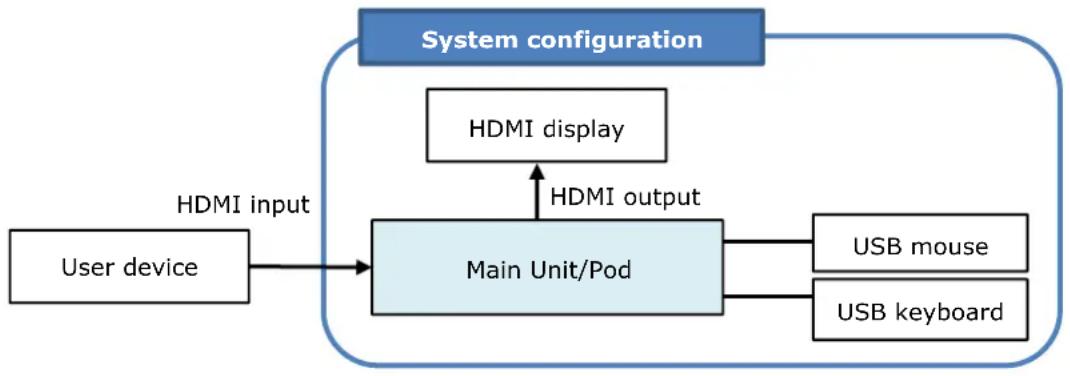
A "small-scale interactive lecture" is a function that can be used with the minimum configuration. The configuration for an interactive lecture is recommended as the base system when evaluating the configuration for other extended configurations.
A small-scale interactive lecture configuration is based on a small classroom or conference room, where the images of computers etc. (user devices) possessed by each participant are displayed by a projector, and the discussion proceeds while switching between the displayed images of devices.
flowchart
graph TD
    A["User device"] --> B["Main Unit/Pod"]
    C["HDMI display"] -->|HDMI output| B
    D["USB mouse"] --> B
    E["USB keyboard"] --> B
    B --> F["System configuration"]
    style A fill:#f9f,stroke:#333
    style C fill:#ccf,stroke:#333
    style D fill:#cfc,stroke:#333
    style E fill:#fcc,stroke:#333
The required equipment is listed below.
| Equipment Quantity Remarks | ||
| HDMI display 1 | LCD TVs, such as BRAVIA, and projectors can be used.More intuitive operation is possible using a touch panel type display. | |
| USB mouse 1 | Used for operation of the main unit/Pod during installation,operation, and maintenance.Not required for operation if using a touch panel device.However, the mouse is required for maintenance use. | |
| USB keyboard | One USB keyboard is recommended for maintenance use.A software keyboard can be used when it is necessary to input characters while using the unit. | |
A network environment is not required to use the minimum configuration.
HDMI outputs of devices, such as laptop computers and cameras, can be connected directly to the HDMI input connectors of the main unit.
Up to four HDMI output devices can be connected with the PEQ-C130, and up to two with the PEQ-C100.
The main unit supports HDCP, enabling connection of a DVD or Blu-ray Disc player to the HDMI input of the unit.
For details about HDCP, see "Precautions When Using HDCP Content" (page 74) in the "Installation and Setup" section.
When using HDMI input on a Pod, you can connect one HDMI output device using an HDMI capture box.
For details about HDMI capture boxes, see "HDMI capture box" (page 60) in the "Installation and Setup" section.
Extended configuration
This section introduces a sample configuration that provides more enhanced functionality.
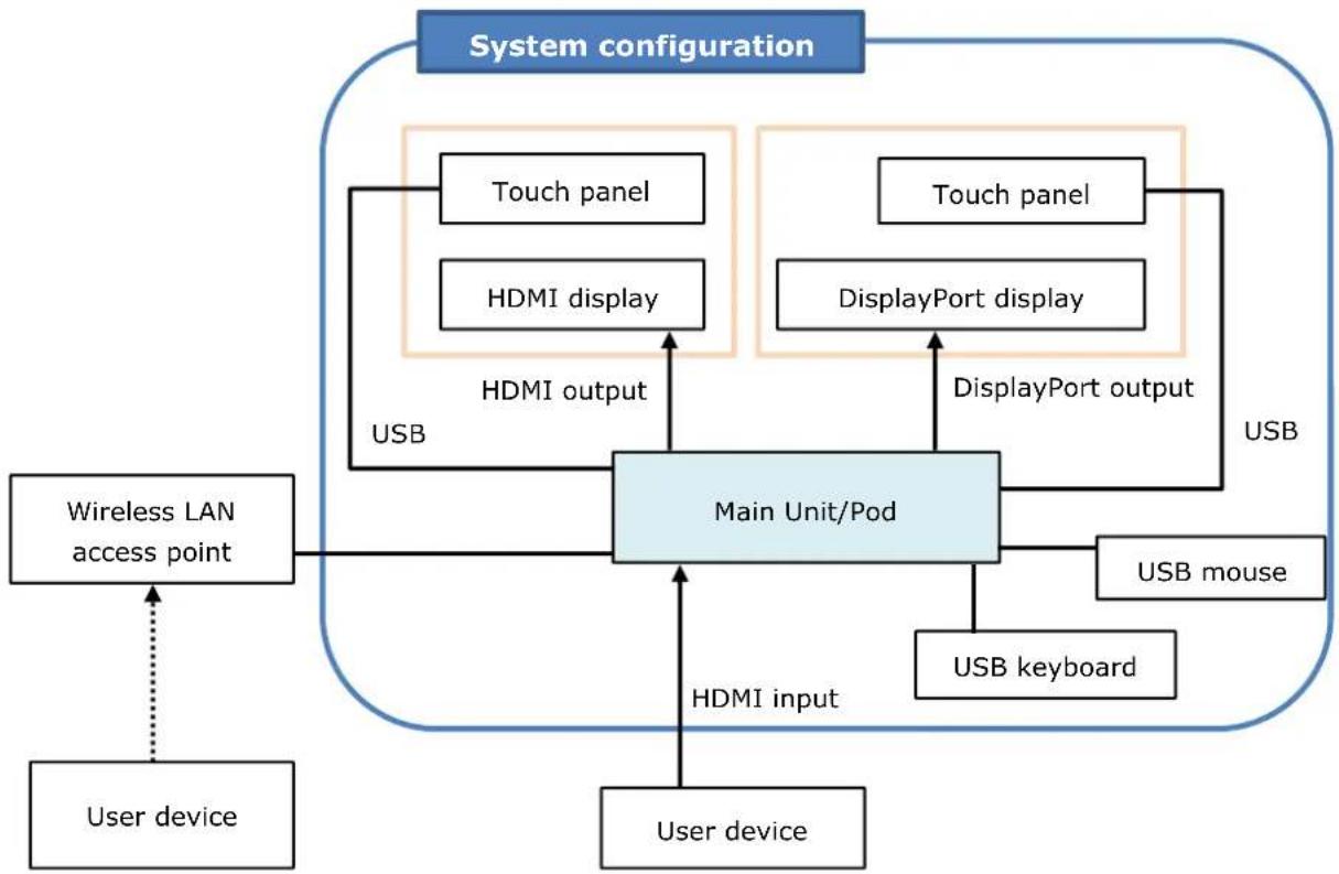
In addition to the base configuration, two displays can be connected to the DISPLAY PORT connectors. The second display can display a different image than the first display. For example, different presentations can be shown on the two displays to support large-scale lectures or meetings.
A second HDMI display can be connected when a DisplayPort-to-HDMI adapter is connected to the DISPLAY PORT connector.
Touch panel displays are used, which allows the presenter to conduct a smooth dynamic session by simply swiping on the screen to switch the displayed image.
If a wireless LAN access point is available, wireless LAN compatible user devices (such as laptop computers and mobile devices) can connect to support control of the main unit/Pod and mirroring (transfer of screen image of user devices to main unit/Pod). A simple system can be constructed using a wireless LAN access point that supports the DHCP function in a small-scale configuration. The LAN connectors of the unit are auto MDI/MDI-X ports, enabling direct connection of a wireless LAN access point using a single LAN cable.
flowchart
graph TD
    A["User device"] --> B["Wireless LAN access point"]
    B --> C["Main Unit/Pod"]
    C --> D["User device"]
    C --> E["HDMI input"]
    C --> F["DisplayPort output"]
    C --> G["USB mouse"]
    C --> H["USB keyboard"]
    C --> I["Touch panel"]
    C --> J["HDMI display"]
    C --> K["USB"]
    C --> L["DisplayPort display"]
    M["System configuration"] --> N["User device"]
    N --> O["Wireless LAN access point"]
    O --> P["User device"]
    P --> Q["HDMI output"]
    Q --> R["Main Unit/Pod"]
    R --> S["User device"]
    R --> T["HDMI display"]
    R --> U["DisplayPort display"]
    R --> V["USB mouse"]
    R --> W["USB keyboard"]
    R --> X["Touch panel"]
* For Pods, it is necessary to select a PC that meets the required specifications. For details, see "Pod" (page 57) in the "Required/Recommended Specifications of Items Available Separately" section.
The required equipment is listed below.
| Equipment Quantity Remarks | ||
| HDMI display 1 Supports connection of an HDMI display. | ||
| DisplayPort display 1 Supports connection of a DisplayPort display. | ||
| USB-type touch panel 2 | By associating two displays with a USB type touch panel, you can operate by touching the screen of each display. This provides more intuitive operation than using a mouse. | |
| USB mouse | 1 | Used for operation of the main unit/Pod during installation, operation, and maintenance.Not required for operation if using a touch panel device. However, the mouse is required for maintenance use. |
| USB keyboard 1 One USB keyboard is recommended for maintenance use.A software keyboard can be used when it is necessary to input characters while using the unit. | ||
| Wireless LAN access point | 1 Connect | to wireless LAN compatible user devices used for remote control of the main unit/Pod and mirroring (transfer of screen image). Each user device can operate using a fixed IP address, but an access point that supports a DHCP server function is recommended for more streamlined operation. |
| User device 6 Used for mirroring or remote control of the main unit/Pod.Mirroring and remote control of the main unit/Pod are supported by installing Vision Exchange App. Remote control of the main unit is also supported from a web browser. | ||
| Vision Exchange App (available for free) | Number of user devices | This dedicated software is for installation on user devices to enable participation with Vision Exchange. Used for mirroring or remote control of the main unit/Pod.The software can be downloaded for free from the following URL. For details about the devices supported for installation of this software, visit the following URL.http://www.sony.com/VEapp |
Internet utilization
Connection to the Internet is required for Skype for Business integration, service/maintenance, and for online update of software.
WAN / Internet
LAN
NAT/Firewall
Layer 2 switch
Wireless LAN access point
Main Unit/Pod
Pod
Wireless LAN
User device
Connect to the Internet using NAT (Network Address Translation) or via a firewall, depending on the appropriate settings according to the network infrastructure.
When configuring NAT and firewall ports, see "List of Used Ports" (page 102) in the Appendix. For details, consult the system administrator.
Maximum number of simultaneous mirroring user devices
The maximum number of user devices for simultaneous mirroring to the main unit/Pod is six.
Network bandwidth
This section describes how to calculate the required network bandwidth.
Specifically, calculate the network bandwidth that the wireless LAN access point must maintain.
You can calculate an estimate of the required bandwidth by visiting the following URL.
https://www.sonycreativesoftware.com/visionexchange/calc
Types of mirroring
There are the following two types of mirroring from a user device to the main unit/Pod.
- Content display mirroring
- Thumbnail display mirroring
The image quality for mirroring thumbnail display from a user device is fixed.
Mirroring from a user device
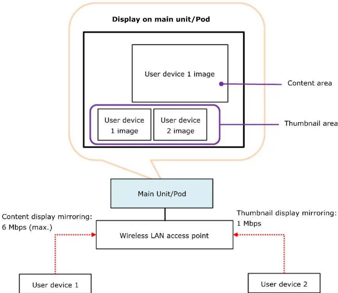
Content display mirroring is high image quality/high throughput mirroring for display of the image of the user device in the content area on the main unit/Pod.
Thumbnail display mirroring is low image quality/low throughput mirroring for display of the image of the user device in the thumbnail area on the main unit/Pod.
These two types are dynamically switched by user operation. Moving the user device image displayed in the thumbnail area on the main unit/Pod into the content area by drag & drop dynamically switches the user device image from thumbnail display mirroring to content display mirroring. Subsequently, moving another image into the content area by drag & drop replaces the user device image display in the content area, and switches the user device image from content display mirroring to thumbnail display mirroring.
Maximum number of content display mirrored images
The maximum number of content display mirrored images is the same as the number of displays connected to the main unit/Pod. When two displays are connected to the main unit/Pod, up to two content display mirroring sources can be used for the two content areas on both displays.
Mirroring throughput
After calculating the number of simultaneous mirroring devices using the equation in "Maximum number of simultaneous mirroring user devices" (page 12), calculate the total throughput of user devices as described below and ensure there is sufficient network bandwidth.
When the main unit/Pod and user devices are using Internet resources other than Vision Exchange, such as streaming from the Internet, also take that load into account to ensure there is sufficient network bandwidth.
Always check system requirements beforehand as the number of devices to connect and network bandwidth will vary depending on the model of wireless LAN access point and the operating environment.
flowchart
graph TD
    A["User device 1 image"] --> B["Main Unit/Pod"]
    C["User device 1 image"] --> B
    D["User device 2 image"] --> B
    E["Content area"] --> B
    F["Thumbnail area"] --> B
    B --> G["Wireless LAN access point"]
    G --> H["User device 1"]
    G --> I["User device 2"]
    G --> J["Content display mirroring: 6 Mbps (max.)"]
    G --> K["Thumbnail display mirroring: 1 Mbps"]
    style A fill:#f9f,stroke:#333
    style C fill:#f9f,stroke:#333
    style D fill:#f9f,stroke:#333
    style E fill:#f9f,stroke:#333
    style F fill:#f9f,stroke:#333
    style G fill:#ccf,stroke:#333
    style H fill:#dfd,stroke:#333
    style I fill:#dfd,stroke:#333
    style J fill:#dfd,stroke:#333
    style K fill:#dfd,stroke:#333
The user device image quality settings and maximum throughput values are given below.
Allow a margin as these values are empirical values only.
The actual throughput will also vary depending on the content matter. Estimate the image quality setting and network bandwidth that needs to be maintained for the intended use.
Throughput when mirroring from a user device to the main unit/Pod
Content display mirroring
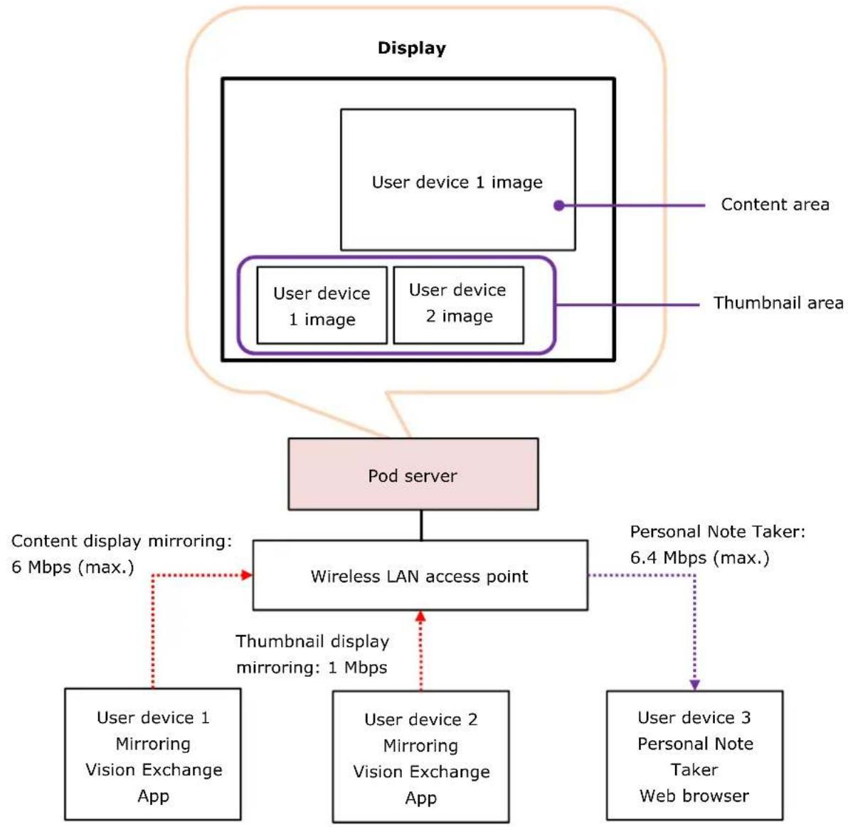
As shown in the preceding diagram, content display mirroring simultaneously generates and displays images in the content area and thumbnail area.
The image quality for content display mirroring from a user device to the main unit/Pod is set in [Setting] screen – [Mirroring] page – [Vision Exchange App. Setting] on the main unit/Pod. For details about operation, refer to the Help Guide.
| Image quality | Resolution | Throughput max. value (when playing video) |
| High (default setting) | Same as display on transmitting device | 6 Mbps |
| Mid 4 Mbps | ||
| Low 1 Mbps |
Includes video and audio throughput.
Thumbnail display mirroring
The throughput when an image is displayed in the thumbnail area is a maximum of 1 Mbps when playing video (includes both the video and audio).
Required network bandwidth calculation equations
Number of user devices is greater than the number of displays connected to the main unit/Pods

$$ = T _ {\text {content}} \times N _ {\text {disp}} + T _ {\text {thumbnail}} \times (N _ {\text {device}} - N _ {\text {disp}}) $$
Number of user devices is less than or equal to the number of displays connected to the main unit/Pods
Required bandwidth ( T_wlan )
=
Throughput when content display mirroring from a user device ( T_content )
×
Number of user devices ( N_device )
=
T_content × N_device
For reference, a sample calculation is described for the following conditions.
- User devices: 2 (with image quality set to [High])
● Number of displays connected to the main unit/Pod: 1 - Margin: 30%
Required bandwidth = 6 Mbps × 1 + 1 Mbps × (2 - 1)
$$ = 7 \mathrm{Mbps} $$
Adding the margin of 30%, 7 Mbps × 1.3 = 9.1 Mbps
Note that if a presentation is predominantly composed of still images, the throughput will be lower and hence the required bandwidth will also be lower. Estimate the network bandwidth to match the intended use.
Active Learning
The unit supports lectures conducted in an active learning form.
Proposed application
"Active learning" encompasses a wide range of activities. A proposed application using the unit is given below.
For details about functions, refer to the Help Guide.
| Term Definition / Description | |
| Classroom A class | room is a room in which active learning takes place. The active learning system using the unit basically is conducted within a classroom. |
| Lectern | Represents a stand or dais used by a lecturer. A display (touch panel) for operating the system, keyboard, mouse, computer/tablet used for lectures are placed here. |
| Table A table is used by several seated participants to promote individual discussion. Generally, multiple tables may be arranged in the classroom. | |
| Main Unit | Represents the unit. The unit is operated mainly by the instructor. |
| Pod PC Software | Software for devices that run on Microsoft Windows to provide some Vision Exchange functionality. The software is mainly operated by the participants. |
| Pod A Mini PC placed on each table in which Pod PC Software is installed. | |
| Pod sharing Function for sharing content between the main unit and Pods. Images shown in the content area of a Pod is shared with the main unit, and images shown in the content area of the main unit is shared with the Pods. Images shown in the content area of the main unit are simultaneously sent to one or more Pods. | |
flowchart
graph TD
    A["Main unit screen"] --> B["Pod sharing"]
    A --> C["Instructor user device screen"]
    B --> D["Pod screen"]
    C --> E["User device screen of participants"]
    D --> F["Mirroring"]
    E --> F
    style A fill:#f9f,stroke:#333
    style B fill:#ccf,stroke:#333
    style C fill:#cfc,stroke:#333
    style D fill:#ffc,stroke:#333
    style E fill:#fcc,stroke:#333
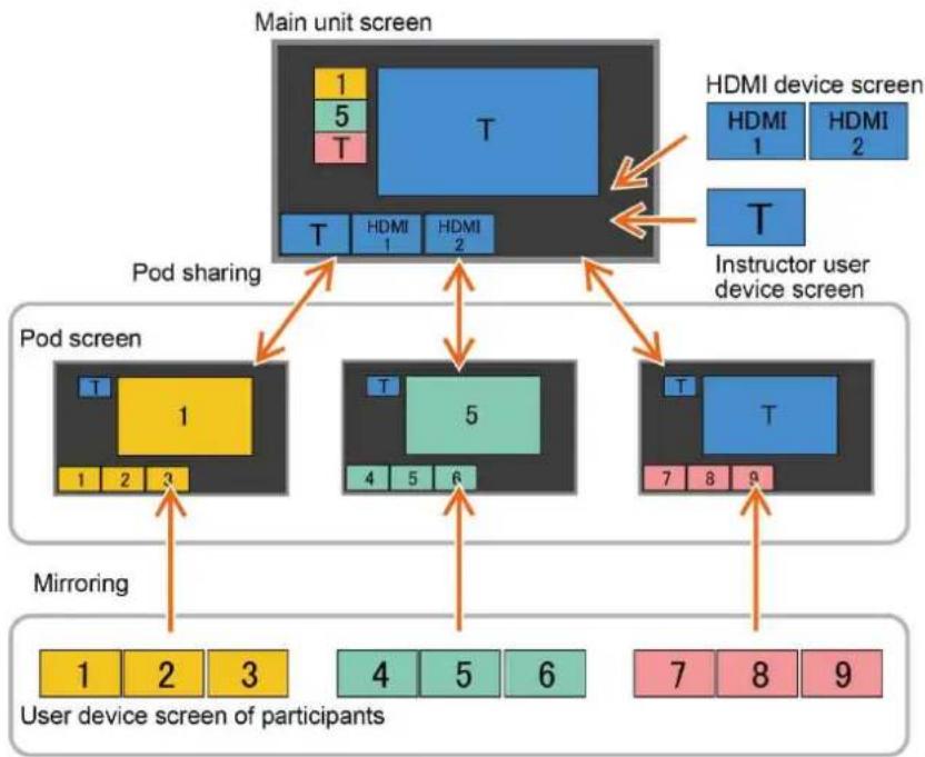
In active learning, participants can conduct a discussion while sharing material using the Pod on each table.
In the same way as the main unit, the screen of a user device, such as a computer or tablet, of a participant can be displayed on a Pod via the network.
The screen of a laptop computer or camera can also be displayed via an HDMI capture box connected to a Pod.
In addition, the image of the content area of the main unit can be displayed on a Pod, or the image of the content area of a Pod can be shared with the main unit.
The system can also display the results of the discussion of each table on a large screen of the main unit for review.
Basic configuration of proposed application
One main unit and several Pods are required to implement an active learning application.
Connect between the main unit and Pods using a wired LAN. Connect between Pods and user devices using either a wired LAN or wireless LAN. A wireless LAN is not absolutely necessary, but a wireless LAN access point is recommended because many devices used by participants may not have a LAN port.
In this configuration, participants can also mirror devices to the display of the main unit used by the instructor and perform other functions on the main unit, not just the Pods.
If this is not required, the access control function of Vision Exchange can be used or the main unit can be configured to limit the number of devices that can connect to the main unit for mirroring to prevent access by participants.
Using the access control function, you can grant or deny permission for mirroring to specific users.
Mirroring to the main unit by anyone other than the instructor can also be prevented by limiting the number of devices that can connect for mirroring to the device used by the instructor.
For details about each type of configuration, refer to the Help Guide.

flowchart
graph TD
    A["Classroom"] --> B["Layer 2 switch"]
    B --> C["Wireless LAN access point"]
    C --> D["Main Unit"]
    D --> E["User device of instructor (computer, etc.)"]
    D --> F["User device of instructor (Wireless LAN device, e.g. tablet)"]
    F --> G["Display"]
    G --> H["Lectern"]
    H --> I["HDMI input"]
    I --> D
    C -.-> J["Wireless LAN"]
    J -.-> K["User device of participant"]
    K --> L["Pod"]
    L --> M["USB mouse"]
    M --> N["Table"]
    N --> O["User device of participant"]
    O --> P["HDMI capture box"]
    P --> Q["Display"]
    Q -.-> L
    style A fill:#f9f,stroke:#333
    style B fill:#ccf,stroke:#333
    style C fill:#cfc,stroke:#333
    style D fill:#fcc,stroke:#333
    style E fill:#cff,stroke:#333
    style F fill:#ffc,stroke:#333
    style G fill:#fcf,stroke:#333
    style H fill:#cff,stroke:#333
    style I fill:#ffc,stroke:#333
    style J fill:#cfc,stroke:#333
    style K fill:#fcc,stroke:#333
    style L fill:#ffc,stroke:#333
    style M fill:#cfc,stroke:#333
    style N fill:#fcc,stroke:#333
    style O fill:#ffc,stroke:#333
    style P fill:#fcc,stroke:#333
    style Q fill:#ffc,stroke:#333
The required equipment is listed below.
For details about the configuration of the main unit, see "Small-Scale Interactive Lecture" (page 8).
| Equipment Quantity | Remarks | |
| HDMI display 1 Supports connection of an HDMI display to a Pod. The use of the display is changeable to accompany each application. | ||
| PEQA-C10 Active Learning license (available separately) | 1 License to enable the Pod sharing function. | |
| Pod 1 or more A Mini PC on which Pod PC Software is installed. One per table. | ||
| Pod PC Software Number of Pods | Application software that provides the Pod functionality. | |
| HDMI capture boxDarkCrystal 750(Model name:CD750) | 1 Box for capturing the HDMI output from a laptop computer or camera and importing into a Pod via USB 3.0.Use this when you want to display an image from a computer or camera on the Pod display. | |
| USB mouse Number of | Pods | Not required for operation if using a touch panel device, but a mouse is required for system maintenance. |
| USB keyboard Maintenance | requirement | One USB keyboard is recommended for maintenance use.A software keyboard can be used when it is necessary to input characters while using the unit. |
| Wireless LAN access point | 1 One access | point can be used in a small-scale configuration.Network bandwidth is discussed in a later section.Connect to wireless LAN compatible user devices used for remote control of the main unit and mirroring (transfer of screen image).Each user device can operate using a fixed IP address, but an access point that supports a DHCP server function is recommended for more streamlined operation. |
| Layer 2 switch 1 One | access point can be used in a small-scale configuration.Network bandwidth is discussed in a later section. | |
Configuration with instructor and participants on separate networks
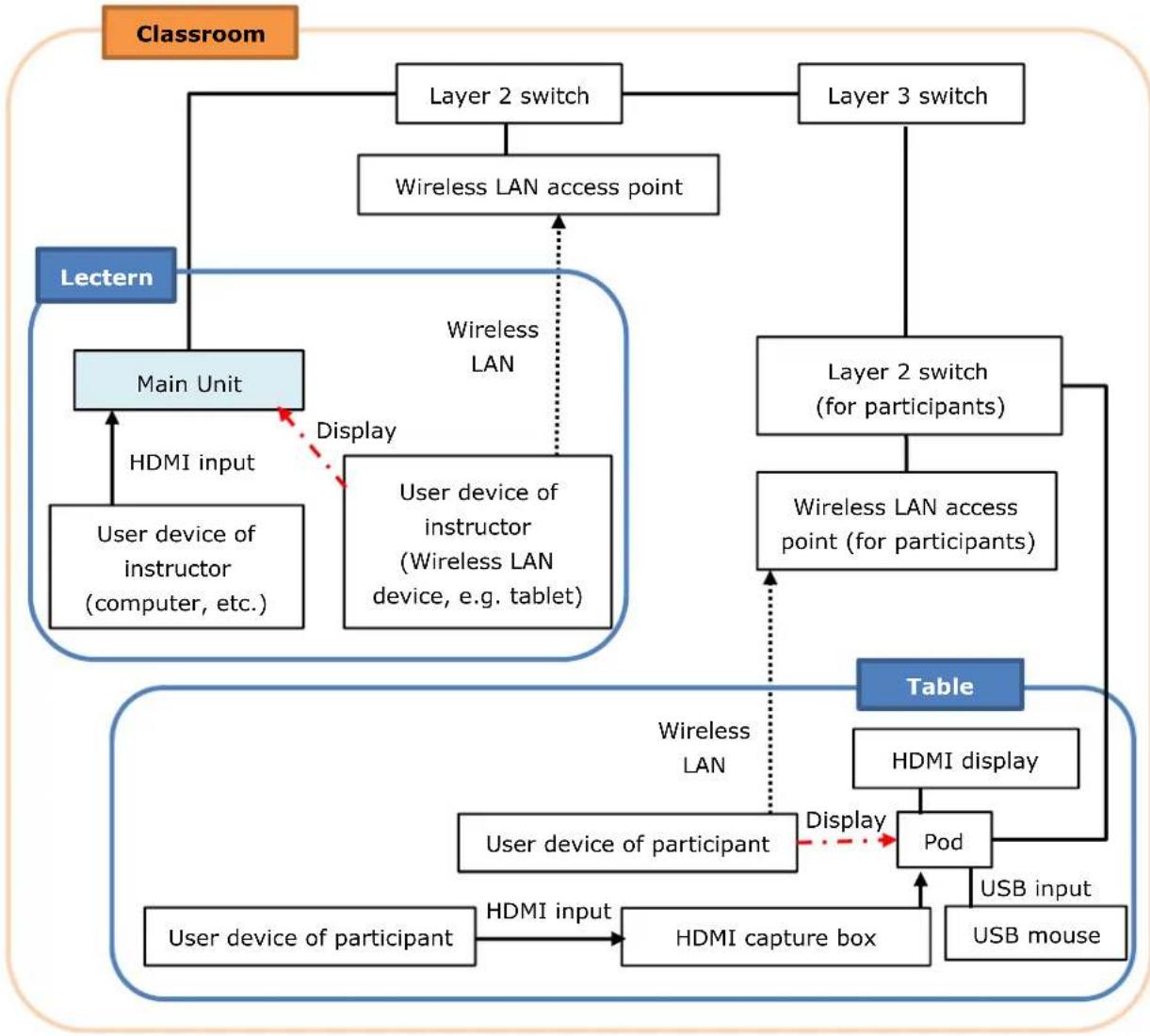
In "Basic configuration of proposed application" (page 18), both the instructor and participants used the same network segment, which allows the participants to mirror devices to the main unit and perform other functions on the main unit, not just the Pods.
If this is not required, the access control function of Vision Exchange can be used on the same network segment, or the main unit can be configured to limit the number of devices that can connect to the main unit for mirroring to prevent access by participants as described earlier.
Alternatively, the network for instructor and network for participants can be separate. The configuration is shown below.
flowchart
graph TD
    A["Classroom"] --> B["Layer 2 switch"]
    B --> C["Wireless LAN access point"]
    C --> D["Layer 3 switch"]
    D --> E["Layer 2 switch (for participants)"]
    E --> F["Table"]
    F --> G["Pod"]
    G --> H["User device of participant"]
    H --> I["HDMI capture box"]
    I --> J["User device of participant"]
    J --> K["User device of instructor (computer, etc.)"]
    K --> L["Main Unit"]
    L --> M["Lectern"]
    M --> N["Wireless LAN"]
    N --> O["User device of instructor (Wireless LAN device, e.g. tablet)"]
    O --> P["HDMI input"]
    P --> Q["Display"]
    Q --> R["User device of instructor (Wireless LAN device, e.g. tablet)"]
    R --> S["Main Unit"]
    S --> T["User device of instructor (computer, etc.)"]
    T --> U["Lectern"]
    U --> V["Wireless LAN access point"]
    V --> W["User device of instructor (Wireless LAN device, e.g. tablet)"]
    W --> X["Main Unit"]
    X --> Y["HDMI input"]
    Y --> Z["Display"]
    Z --> AA["User device of instructor (Wireless LAN device, e.g. tablet)"]
    AA --> AB["Lectern"]
    AB --> AC["Wireless LAN access point"]
    AC --> AD["User device of instructor (Wireless LAN device, e.g. tablet)"]
    AD --> AE["Lectern"]
    AE --> AF["Wireless LAN access point"]
    AF --> AG["User device of instructor (Wireless LAN device, e.g. tablet)"]
    AG --> AH["Lectern"]
    AH --> AI["Wireless LAN access point"]
    AI --> AJ["User device of instructor (Wireless LAN device, e.g. tablet)"]
    AJ --> AK["Lectern"]
    AK --> AL["Wireless LAN access point"]
    AL --> AM["Lectern"]
    AM --> AN["Wireless LAN access point"]
    AN --> AO["User device of instructor (Wireless LAN device, e.g. tablet)"]
    AO --> AP["Lectern"]
    AP --> AQ["Wireless LAN access point"]
    AQ --> AR["Lectern"]
    AR --> AS["Wireless LAN access point"]
    AS --> AT["Lectern"]
    AT --> AU["Wireless LAN access point"]
    AU --> AV["Lectern"]
In this configuration, with appropriate routing configured in the layer 3 switch, access to the main unit from the user devices of participants can be controlled while implementing Pod sharing between the main unit and Pods.
For details about configuration, consult the system administrator.
Maximum number of simultaneous mirroring user devices
The maximum number of user devices for simultaneous mirroring, using Vision Exchange App, to the main unit or each Pod is six per main unit and per Pod.
Extended configuration of multiple Pods
Up to 10 pods can be connected to a single main unit. When the maximum number (six) of user devices are connected to each Pod, network traffic may become a problem.
For details, see "Network bandwidth" below.
Use multiple wireless LAN access points and layer 2 switches according to the required network bandwidth.
Network bandwidth
This section describes how to calculate the required network bandwidth.
Specifically, calculate the network bandwidth that the wireless LAN access point and layer 2 switch must maintain.
You can calculate an estimate of the required bandwidth by visiting the following URL.
https://www.sonycreativesoftware.com/visionexchange/calc
For details about mirroring from a user device to the main unit or a Pod, see "Network bandwidth" (page 12) in the "Small-Scale Interactive Lecture" section.
Pod sharing throughput
In active learning, in addition to the throughput for mirroring, the throughput for Pod sharing between the main unit and Pods also occurs.
Similar to mirroring of user devices, there are two types of Pod sharing: content display Pod sharing for display of high quality/high throughput images in the content area, and thumbnail display Pod sharing for display of low image quality/low throughput images in the Pod sharing area.
These two types are dynamically switched by user operation. Moving the image displayed in the Pod sharing area on the main unit into the content area by drag & drop dynamically switches the image from thumbnail display Pod sharing to content display Pod sharing.
Subsequently, moving another image into the content area by drag & drop replaces the image display in the content area, and switches the image from content display Pod sharing to thumbnail display Pod sharing.
Maximum number of content display Pod sharing images from a Pod to the main unit
The maximum number of content display Pod sharing images from a Pod to the main unit is the same as the number of displays connected to the main unit. When two displays are connected to the main unit, up to two content display Pod sharing sources can be used for the two content areas on both displays.
Maximum number of content display Pod sharing images from the main unit to a Pod
Content display Pod sharing is used when displaying the image shown in the content area of the main unit in full-screen mode on a Pod.
Content display Pod sharing is also used when the [Presentation] button is pressed to display the image shown in the content area of the main unit in full-screen mode on all Pods.
Therefore, the maximum number of content display Pod sharing images from the main unit to a Pod is the same as the number of connected Pods.
Thumbnail display Pod sharing
Thumbnail display Pod sharing is used between the main unit and Pods when content display Pod sharing is not being used between the main unit and Pods.
Network bandwidth diagram for active learning
Legend
Dotted arrow: Transfer using wired LAN or wireless LAN
Solid arrow: Transfer using wired LAN

flowchart
graph TD
    A["Main Unit"] --> B["Pod 1"]
    A --> C["Layer 2 switch"]
    C --> D["Wireless LAN access point"]
    D --> E["(Eqn. A) × Number of Pods"]
    D --> F["(Eqn. A) × Number of Pods"]
    D --> G["(Eqn. A) × Number of Pods"]
    D --> H["(Eqn. A) × Number of Pods"]
    D --> I["(Eqn. A) × Number of Pods"]
    J["Display on main unit"] --> K["Pod 1 content area image"]
    J --> L["Pod sharing area display: 6 Mbps (max.)"]
    J --> M["Pod sharing area display: 1 Mbps"]
    N["User device 1 image"] --> O["Content area image of main unit"]
    N --> P["User device 1 image"]
    Q["User device 2 image"] --> R["Content area pod sharing area"]
    Q --> S["Thumbnail area"]
Pod sharing throughput between main unit and Pods
The video quality settings and maximum throughput values for Pod sharing are given below. Allow a margin as these values are empirical values only.
The actual throughput will also vary depending on the content matter. Estimate the image quality setting and network bandwidth that needs to be maintained for the intended use.
When displaying in the content area
As shown in the preceding diagram, content display mirroring simultaneously generates and displays images in the content area and Pod sharing area.
The image quality for content display Pod sharing is set on the [Setting] screen – [Pod Sharing] page – [Video quality for Pod Sharing] of the main unit.
For details about operation, refer to the Help Guide.
| Image quality | Resolution | Throughput max. value (when playing video) |
| High (default setting) | Same as display on transmitting device | 6 Mbps |
| Mid 4 Mbps | ||
| Low 1 Mbps |
Includes video and audio throughput.
When displaying in the Pod sharing area
The throughput when an image is displayed in the Pod sharing area is a maximum of 1 Mbps when playing video (includes both the video and audio).
Required network bandwidth calculation equations
There are three types of network bandwidth required for Pod sharing.
● Network bandwidth that the wireless LAN access point must maintain
● Network bandwidth that must be maintained between Pod and layer 2 switch
● Network bandwidth that must be maintained between main unit and layer 2 switch
For reference, a sample calculation is described for the following conditions.
- User devices: 2 (with image quality set to [High])
- Pods: 1
● Number of displays connected to the main unit: 1 - Margin: 30%
Network bandwidth that the wireless LAN access point must maintain
Calculation equation
Required bandwidth = Total throughput of devices connected to each Pod × Number of Pods ( N_pod )
Throughput of devices connected to a Pod
Calculate the throughput corresponding to the red arrow in "Network bandwidth diagram for active learning" (page 23).
The total throughput of devices connected to a Pod or the main unit is calculated using the same equations described in "Network bandwidth" (page 12) in the "Small-Scale Interactive Lecture" section.
The result of the calculation multiplied by the number of Pods ( N_pod ) is the network bandwidth that the wireless LAN access point must maintain.
Total throughput of devices connected to a Pod (Eqn. A)
Number of user devices is greater than the number of displays connected to the main unit/Pods
$$ = \left{T _ {\text { content }} \times N _ {\text { disp }} + T _ {\text { thumbnail }} \times \left(N _ {\text { device }} - N _ {\text { disp }}\right) \right} $$
Number of user devices is less than or equal to the number of displays connected to the main unit/Pods
$$ = T _ {\text { content }} \times N _ {\text { device }} $$
Required bandwidth = (Eqn. A) × Number of Pods (Npod)
$$ = {6 \text { Mbps } \times 2 + 1 \text { Mbps } \times (2 - 1) } \times 1 $$
$$ = 1 3 \mathrm{Mbps} $$
Network bandwidth that must be maintained between Pod and layer 2 switch Calculation equation
Required bandwidth ( T_pod ) = Total throughput from wireless LAN access point to Pod (Eqn. A)
× Number of Pods
+ Total throughput from Pods to main unit (Eqn. B)
+ Total throughput from main unit to Pods (Eqn. C)
Use the value calculated in "Network bandwidth that the wireless LAN access point must maintain" (page 24) for the total throughput from wireless LAN access point to Pod.
Use the following equations to calculate the total throughput from Pods to main unit and the total throughput from main unit to Pods.
Calculation equation of throughput from Pods to main unit
Calculate the throughput corresponding to the blue arrow in "Network bandwidth diagram for active learning" (page 23).
Required bandwidth
=
Throughput of content display Pod sharing from a Pod to the main unit ( T_pod_content )
×
Number of displays connected to the main unit or number of Pods, whichever is smaller ( N_disp or N_pod )
* N_disp = 0 if user devices are mirroring by direct connection to the main unit.
+
Throughput of thumbnail display Pod sharing from a Pod to the main unit (T podThumbnail)
×
Number of Pods - Number of displays connected to the main unit (N_pod - N_disp)
=
$$ T _ {\text { pod_content }} \times N _ {\text { disp }} + T _ {\text { pod_thumbnail }} \times (N _ {\text { pod }} - N _ {\text { disp }}) \dots \tag {Eqn.B} $$
$$ = 6 \text { Mbps } \times 1 + 1 \text { Mbps } \times (1 - 1) $$
$$ = 6 \mathrm{Mbps} $$
Calculation equation of throughput from main unit to Pods
Calculate the throughput corresponding to the green arrow in "Network bandwidth diagram for active learning" (page 23).
Required bandwidth = Throughput of content display Pod sharing from main unit to a Pod
$$ (T _ {\text { pod_content }}) $$
$$ \times \text { Number of Pods } (N _ {\text { pod }})...... (\text { Eqn. C }) $$
$$ = 6 \mathrm{Mbps} \times 1 $$
$$ = 6 \mathrm{Mbps} $$
From the above calculation equation, the required network bandwidth that must be maintained between Pod and layer 2 switch is given below.
Required bandwidth ( T_pod ) = Total throughput from wireless LAN access point to Pod (Eqn. A)
$$ \times \text { Number of Pods } $$
$$ + \text { Total throughput from Pods to main unit } (\text { Eqn. } B) $$
$$ + \text { Total throughput from main unit to Pods } (\text { Eqn. C }) $$
$$ = 7 \mathrm{Mbps} + 6 \mathrm{Mbps} + 6 \mathrm{Mbps} $$
$$ = 1 9 \mathrm{Mbps} $$
Adding the margin of 30%, 19 Mbps × 1.3 = 24.7 Mbps
Network bandwidth that must be maintained between main unit and layer 2 switch Calculation equation
Required bandwidth ( T_main ) = Total throughput from Pods to main unit (Eqn. B)
+ Total throughput from main unit to Pods (Eqn. C)
Use the values calculated in "Network bandwidth that must be maintained between Pod and layer 2 switch" (page 25) for the values of equations B and C.
$$ = 6 \mathrm{Mbps} + 6 \mathrm{Mbps} $$
$$ = 1 2 \mathrm{Mbps} $$
Adding the margin of 30%, 12 Mbps × 1.3 = 15.6 Mbps
Large-Scale Interactive Lecture
Proposed application
A "large-scale interactive lecture" is a lecture in which content, such as the video from devices of the instructor and some participants or a whiteboard image, is distributed to the web browsers of 21 to 100 participants.
Images from user devices of the instructor or some participants can be displayed on HDMI displays and other output devices using mirroring, and text and line annotations can be added to the images by the instructor or participants to create an interactive lecture.
Participants can also receive content using the web browser of their own user devices. Users can add their own text memos or line annotations to the received images and can also capture the images to their user devices.
For details about functions, refer to the Help Guide.
| Term Definition / Description | |
| Pod server | Server machine running Windows Server OS with Pod PC Software installed.Software with some of the features of Vision Exchange is installed and is operated mainly by the instructor. |
| Personal Note Taker function | This is a function that captures the image displayed on the display of a Pod server as a still picture, and distributes it to multiple participants at the same time every few seconds.Participants can receive content using the browser of their own user devices. Users can add their own text memos or line annotations to the received images and can also capture and save the images to their user devices. |
Note
There is no limitation on the simultaneously connected user devices, but the recommended maximum number of simultaneously connected devices is 20, since the main unit and Pods use the Windows 10 client OS. For details, check the contents of the Microsoft Windows EULA (End User License Agreement).
To connect 21 or more devices simultaneously, use of a Pod server running Windows Server OS is recommended
Typical simultaneous connection of 20 devices
Make sure that the total number of devices connected using the following method is 20 or less. When a main unit and Pods are connected, the total connections include the mutual devices connected to each other.
- Main Unit
- Pod
- Vision Exchange App
- Personal Note Taker function using web browser
Note
The maximum number of devices that can be mirrored from Vision Exchange App is six. In the Windows EULA, the number of devices that can be connected is stipulated under "Device connections." For example, if Vision Exchange App and the Personal Note Taker function in a web browser are both used on a single device, the number of connected devices is counted as one device.
Configuration
A large-scale interactive lecture configuration is based on a classroom or conference room, where the images of computers etc. (user devices) possessed by each participant are displayed by a projector, and the discussion proceeds while switching between the displayed images of devices, while those images are distributed to other participants.

flowchart
graph TD
    A["System configuration"] --> B["Pod server"]
    B --> C["User device"]
    B --> D["User device Web browser Personal Note Taker"]
    B --> E["User device Vision Exchange App."]
    B --> F["USB mouse"]
    B --> G["USB keyboard"]
    B --> H["HDMI display"]
    B --> I["Touch panel"]
    B --> J["USB input"]
    B --> K["USB output"]
    B --> L["HDMI output"]
    B --> M["HDMI display"]
    B --> N["Handheld screen"]
    B --> O["Handheld screen with USB"]
    B --> P["Handheld screen with HDMI output"]
    B --> Q["Handheld screen with USB input"]
    B --> R["Handheld screen with HDMI display"]
    B --> S["Handheld screen with Touch panel"]
    B --> T["Handheld screen with HDMI display"]
    B --> U["Handheld screen with Touch panel"]
    style A fill:#f9f,stroke:#333
    style B fill:#ccf,stroke:#333
    style C stroke-dasharray: 5 5
    style D stroke-dasharray: 5 5
    style E stroke-dasharray: 5 5
    style F stroke-dasharray: 5 5
    style G stroke-dasharray: 5 5
    style H stroke-dasharray: 5 5
    style I stroke-dasharray: 5 5
    style J stroke-dasharray: 5 5
    style K stroke-dasharray: 5 5
    style L stroke-dasharray: 5 5
    style M stroke-dasharray: 5 5
    style N stroke-dasharray: 5 5
    style O stroke-dasharray: 5 5
    style P stroke-dasharray: 5 5
    style Q stroke-dasharray: 5 5
The required equipment is listed below.
| Equipment Quantity Remarks | ||
| Pod server 1 Windows server on which Pod PC Software is installed. Prepare a Windows Server license. A Windows Server Client Access License (CAL) is also required as a client license. | ||
| Pod PC Software 1 Application software are that provides the interactive lecture functionality. | ||
| PEQA-C10 Active Learning license (available separately) | 1 License to activate Pod PC Software. | |
| HDMI display 2 (max.) | Use HDMI displays | |
| USB-type touch panel | 2 (max.) | By associating two displays with a USB type touch panel, you can operate by touching the screen of each display. This provides more intuitive operation than using a mouse. |
| USB mouse 1 Used for operation of the main unit during installation, operation, and maintenance. Not required for operation if using a touch panel device. However, the mouse is required for maintenance use. | ||
| USB keyboard 1 One USB keyboard is recommended for maintenance use.A software keyboard can be used when it is necessary to input characters while using the unit. | ||
| HDMI capture box 1 Box for capturing the HDMI output from a laptop computer or camera and importing into a Pod server via USB 3.0.Use this when you want to display an image from a computer or camera on the Pod server display. | ||
| Wireless LAN access point | 1 Connect to wireless LAN compatible user devices used for remote control of the main unit and mirroring (transfer of screen image). Each user device can operate using a fixed IP address, but an access point that supports a DHCP server function is recommended for more streamlined operation. | |
| User device 100 | (max.) | Used for mirroring or remote control of the main unit. Mirroring and remote control of the main unit are supported by installing Vision Exchange App. Pod server image receiving using the Personal Note Taker function and remote operation from a web browser are also supported. |
| Vision Exchange App (available for free) | Number of user devices | This dedicated software is for installation on user devices to enable participation with Vision Exchange. Used for mirroring or remote control of the main unit. The software can be downloaded for free from the following URL. For details about the devices supported for installation of this software, visit the following URL.http://www.sony.com/VEapp |
The maximum number of user devices that a Pod server can mirror simultaneously using Vision Exchange App is six.
Maximum number of simultaneous user devices for Personal Note Taker function
The Personal Note Taker function allows participants to open a web browser on their own user device, access the IP address of the Pod server, login, and then receive images that the Pod server displays.
The content is updated about once a second.
Users can add their own text memos or line annotations to the received images and can also capture the images to their user devices.
For details about operation, refer to the Help Guide.
The maximum number of user devices that can simultaneously receive images from a Pod server using the Personal Note Taker function is 100.
This section describes how to calculate the required network bandwidth.
Specifically, calculate the network bandwidth that the wireless LAN access point must maintain.
flowchart
graph TD
    A["Pod server"] --> B["Wireless LAN access point"]
    B --> C["User device 1 Mirroring Vision Exchange App"]
    B --> D["User device 2 Mirroring Vision Exchange App"]
    B --> E["User device 3 Personal Note Taker Web browser"]
    B --> F["Content display mirroring: 6 Mbps (max.)"]
    B --> G["Thumbnail display mirroring: 1 Mbps"]
    H["User device 1 image"] --> I["Display"]
    J["User device 2 image"] --> I
    K["Content area"] --> I
    L["Thumbnail area"] --> I
    I --> M["Display"]
    style A fill:#f9f,stroke:#333
    style B fill:#ccf,stroke:#333
    style C fill:#cfc,stroke:#333
    style D fill:#cfc,stroke:#333
    style E fill:#cfc,stroke:#333
    style F fill:#fcc,stroke:#333
    style G fill:#fcc,stroke:#333
    style H fill:#ffc,stroke:#333
    style I fill:#ffc,stroke:#333
    style J fill:#ffc,stroke:#333
    style K fill:#ffc,stroke:#333
    style L fill:#ffc,stroke:#333
Mirroring throughput
Calculate the mirroring throughput using Vision Exchange App of a user device as described in "Network bandwidth" (page 12) in the "Small-Scale Interactive Lecture" section.
Personal Note Taker function throughput
After calculating the number of devices simultaneously using the Personal Note Taker function, calculate the total throughput of user devices as described below and ensure there is sufficient network bandwidth.
When the Pod server and user devices are using Internet resources other than Vision Exchange, such as streaming from the Internet, also take that load into account to ensure there is sufficient network bandwidth.
Always check system requirements beforehand as the number of devices to connect and network bandwidth will vary depending on the model of wireless LAN access point and the operating environment.
The video quality and throughput used for the Personal Note Taker function is set on the [Setting] screen - [Viewer] page of the Pod server.
For details about operation, refer to the Help Guide.
The configurable image quality and throughput are given below.
Allow a margin of 10% to 30% when calculating the network bandwidth as these values are empirical values only.
The actual throughput will vary depending on the subject.
| Image quality | Resolution | Throughput max. value (when playing video) |
| High (default setting) | Same as display on transmitting device | 6.4 Mbps |
| Mid 4 Mbps | ||
| Low 1.6 Mbps |
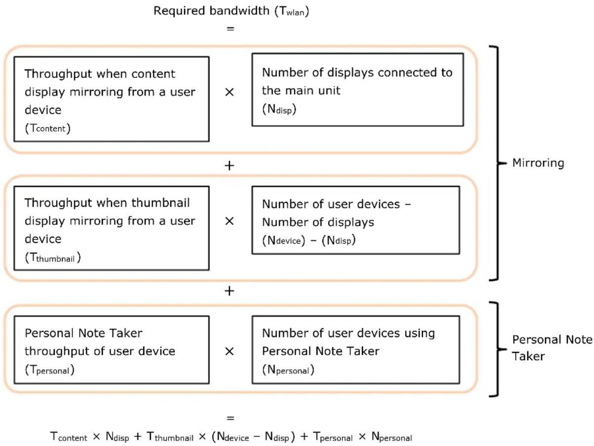
Required network bandwidth calculation equations
The bandwidth to maintain is the sum of the following two types.
- Mirroring with user device Vision Exchange App
● Personal Note Taker function distribution of content to user device browser
flowchart
graph TD
    A["Required bandwidth (T_wlan)"] --> B["Throughput when content display mirroring from a user device (T_content)"]
    B --> C["×"]
    C --> D["Number of displays connected to the main unit (N_disp)"]
    A --> E["+"]
    E --> F["Throughput when thumbnail display mirroring from a user device (T_thumbnail)"]
    F --> G["×"]
    G --> H["Number of user devices - Number of displays (N_device) - (N_disp)"]
    A --> I["+"]
    I --> J["Personal Note Taker throughput of user device (T_personal)"]
    J --> K["×"]
    K --> L["Number of user devices using Personal Note Taker (N_personal)"]
    A --> M["Mirroring"]
    I --> N["Personal Note Taker"]
    M --> O["T_content × N_disp + T_thumbnail × (N_device - N_disp) + T_personal × N_personal"]
For reference, a sample calculation is described for the following conditions.
- User devices mirroring: 2 (with image quality set to [High])
- User devices using Personal Note Taker function: 100 (with image quality set to [High])
● Number of displays connected to the main unit: 1 - Margin: 30%
Required bandwidth = 6 Mbps × 1 + 1 Mbps × (2 - 1) + 6.4 Mbps × 100
$$ = 6 4 7 \mathrm{Mbps} $$
Adding the margin of 30%, 647 Mbps × 1.3 = 841.1 Mbps
If joining an existing network, it is necessary to consider whether there is surplus bandwidth available for Vision Exchange from the existing bandwidth usage. If necessary, enhance the network infrastructure, for example by adding wireless LAN access points.
If the required network bandwidth cannot be maintained, reduce the number of simultaneous connections, or set the image quality to Mid or Low to reduce the bandwidth usage for Vision Exchange. Note that the resulting picture will be degraded if the image quality setting is reduced.
Note that if a presentation is predominantly composed of still images, the throughput will be lower and hence the required bandwidth will also be lower. Estimate the network bandwidth to match the intended use.
Skype for Business Integration
Skype for Business (SfB) is an integrated web conferencing platform that provides video/audio conferencing, screen sharing, chat (instant messaging), presence confirmation, and other functions over the network.
The Skype for Business functionality can be used from the user interface of the unit by installing Skype for Business.
Active Directory user accounts can also use Skype for Business through a separate integration between Skype for Business and Active Directory. On Pods that meet the following conditions, when logged in to Windows as an Active Directory user, the Pod is automatically logged in to Skype for Business when you start a Vision Exchange meeting.
- Vision Exchange is installed as a Windows desktop application
● Active Directory integration is configured - Logged in to Windows as an Active Directory user
For details about Active Directory, consult the system administrator.
Notes
● The following functions are not supported.
- Outlook integration
- File sharing
- Teams integration
- For the chat function, Vision Exchange supports only the reception and display of chats. Chat message composition and sending are not available.

flowchart
graph TD
    A["HDMI display"] --> B["Main Unit or Pod"]
    B --> C["USB"]
    B --> D["MIC-IN or USB"]
    B --> E["Microphone"]
    B --> F["Speaker"]
    G["SRG-120DU HD Color Video Camera"] --> B
    H["Network"] --> B
    I["HDMI output"] --> B
    J["LINE-OUT or USB"] --> B
The required equipment is listed below.
| Equipment Quantity | Remarks | |
| Skype for Business 2015Basic Client (Microsoft free software) | 1 Skype for Business software. Skype for Business is enabled for use by installing the software in the system.For details about installation, see “Installing Skype for Business” (page 80) in the “Installation and Setup” section. | |
| Skype for Business account | 1 User account for signing in to Skype for Business. A user account can be obtained by purchasing a Skype for Business Standalone plan or Office 365 package plan.Users who already have an account can already use this service.For details about purchasing and using an account, contact Microsoft or a Skype for Business partner.NoteAccounts that cannot be used in Vision Exchange also exist. For details, contact your sales representative. | |
| SRG-120DU HD Color Video Camera (available separately) | 1 Use to shoot video within a room and to send a signal to a connected party.NotesA USB 3.0 cable certified by the USB-IF Compliance Program is required to connect the SRG-120DU.The unit supports UVC-compatible USB cameras as the camera used for Skype for Business. Connection with a camera other than the SRG-120DU is not covered by the operation guarantee. Verify correct operation sufficiently before use.Installation is the responsibility of the system administrator. | |
| Microphone 1 Use to capture audio within | a room and to senda signal to a connected party.(MIC-IN and USB can be selected in the menu.)NoteA microphone is required. You cannot join a Skype for Business video conference if one is not connected. | |
| Speaker 1 Use to play audio received from | a connected party.(LINE-OUT and USB can be selected in the menu.)NoteA speaker is required. You cannot join a Skype for Business video conference if one is not connected. | |
Notes
- Skype for Business has audio signal processing functions, such as echo canceling and noise canceling. These functions cannot be disabled. If used together with an external echo canceler, the volume may suddenly drop or fluctuate.
- Evaluate and determine whether the built-in echo canceling function is sufficient. If the echo canceling is insufficient, consider adding a device that has an echo canceling function separately. In this case, double echo cancellation will be applied, but there is no problem in function.
- Check that the date and time are set correctly on the main unit and Pods. It may not be possible to sign in to Skype for Business if the settings are incorrect.
- The SRG-120DU transmits an uncompressed image signal using a USB cable. Accordingly, the CPU performance can be significantly affected, even when the image is not being displayed. Set the output resolution to 1280×720/29.97 using the SYSTEM SELECT switch on the rear of the SRG-120DU. When finished, reboot the SRG-120DU and the main unit.
- Correct operation is not guaranteed when connecting and disconnecting USB cables during SRG-120DU operation. If you inadvertently disconnect a USB cable, reconnect the USB cable and then reboot the system. Before connecting or disconnecting cables, make sure that the power supply is first turned off.
Connection and control
Skype for Business Online and on-premises Skype for Business Server are cloud services which can be used to communicate with not only a main unit or Pods, but also with other Skype for Business clients on other devices such as computers. Multipoint conferencing is also supported.
The network structure will vary depending on the application. A typical structure is shown below.

flowchart
graph TD
    A["Main Unit"] -->|Location 1| B["On-premises server"]
    C["Pod"] -->|Location 1| B
    B --> D["Skype for Business Server"]
    D --> E["Active Directory"]
    F["Laptop computer SfB client"] -->|Location 2| G["Location 3"]
    H["Internet"] -->|Location 2| I["Skype for Business Online"]
    I --> J["Skype for Business Server"]
    style A fill:#cce5ff,stroke:#333
    style C fill:#cce5ff,stroke:#333
    style F fill:#cce5ff,stroke:#333
    style H fill:#cce5ff,stroke:#333
    style B fill:#d4edda,stroke:#333
    style D fill:#d4edda,stroke:#333
    style I fill:#d4edda,stroke:#333
    style E fill:#d4edda,stroke:#333
    style J fill:#d4edda,stroke:#333
The main unit and Pods must be connected to the Internet.
Notes
- Skype session using peer-to-peer connection method are not used. Only conference call Skype sessions are used. Conference call sessions are used for both 1-to-1 communication and multipoint communication.
- For a multipoint conference, specifications such as the maximum number of participants that can participate in a single Skype for Business conference call conform to Lync/Skype for Business specifications.
- Operation using the following versions has been verified for configurations using on-premises servers.
- Skype for Business Server 2015
- Active Directory function in Windows Server 2016
- When using an on-premises server, you may need to install certificates used by the on-premises server for the main unit and Pods. For details, contact the administrator of the on-premises server.
- For details about Skype for Business specifications, check the Microsoft website or contact Microsoft.
-
Laptop computer and other Skype for Business clients require more steps than the normal procedure only when making a one-on-one call to Vision Exchange.
-
In a Skype for Business client, user A initiates a call.
- In Vision Exchange, the placed call is displayed on the screen.
- User B clicks the acknowledge button on the call screen.
Normally, this would connect the call, but the following additional steps are required. - Vision Exchange automatically ends the call and sends a call to the caller. Simultaneously, a chat invitation is sent to the caller.
- The received chat invitation is displayed in the Skype for Business client.
- User A clicks the chat invitation, and the call is connected.
Network bandwidth
The Skype for Business specifications (such as video and audio) and network requirements (such as usage bandwidth) required to design the network bandwidth conform to the Lync/Skype for Business client from Microsoft.
For details about video, audio, and screen sharing in the Lync/Skype for Business client, visit the following websites. Alternatively, contact Microsoft.
Video and audio
For details about video resolution and minimum/maximum payload bit rates, visit the following website.
It displays tables for codecs, resolution, and corresponding minimum/maximum payload bit rates.
URL:
https://docs.microsoft.com/en-us/skypeforbusiness/plan-your-deployment/network-requirements/network-requirements
Item:
Network bandwidth requirements for media traffic > Video Resolution Bandwidth
The codec and resolution are automatically adjusted depending on the network status and other factors.
Also, in video scenes with little or no motion, the bit rate temporarily decreases as encoding is skipped, so the actual bit rate will also change depending on the content of the video (the amount of image movement).
Therefore, make an initial estimate of bandwidth based on the codec, bandwidth, and resolution for standard scenarios.
For the codec, bandwidth, and resolution in standard scenarios, refer to the "Audio/Video Capacity Planning for Conferences" section at the URL above.
Screen sharing
For details about network bandwidth required for screen sharing, visit the following website. URL:
https://docs.microsoft.com/en-us/skypeforbusiness/manage/video-based-screen-sharing Item:
Capacity planning
Typically, when sharing a screen displaying content, the throughput reduces when the movement in the image is small. Conversely, when sharing a screen displaying a lot of movement, such as a video, the throughput increases.
Installing an SSL certificate
An SSL certificate must be installed on the main unit/Pod in order to connect from a user device to the main unit/Pod for Skype for Business operation.
- Prepare a local DNS server.
- Set the domain name on each main unit/Pod.
An independent domain or subdomain is required for each main unit/Pod. - Set the IP address and domain name of each main unit/Pod in the local DNS server.
- Set the DNS server name on the local network gateway to which the main unit/Pod belongs.
-
Obtain a domain server certificate from a public certificate authority or local certificate authority.
When obtaining a server certificate, use an official certificate authority when using an official certificate, or use a local certificate authority when using a local PKI certificate. -
Set the obtained certificate in IIS on each main unit/Pod.
-
Open [Control Panel] > [Internet Information Services (IIS) Manager], and import the SSL certificate using [Server Certificates].
- On the [Connections] pane, select [Default Web Site]. In the IIS group, select [SSL Settings] and open the [Site Bindings] dialog box.
-
Set the type to "https", add port 443, and select the imported certificate.
-
Install the root certificate on the user device (if the domain server certificate was obtained from a local certificate authority).
-
Set [Domain Name] on the [Network] page of the [Setting] screen on the main unit/Pod. On the Vision Exchange App side, activate domain login mode in the settings, and log in using the domain name. For details, refer to the Help Guide.
Notes
- Be mindful of the expiration date of the SSL certificate during operation.
- Install the SSL certificate on each main unit/Pod in the system, and operate using domain names. Also, be sure to operate the Vision Exchange App in domain login mode. It will not operate correctly when logged in using the IP address or room name.
- If you do not enter the domain name on the [Network] page of the [Setting] screen on both the main unit/Pod, some functions will not operate correctly.
- If you are operating Vision Exchange in application mode with general user permissions, start Vision Exchange again with administrator permissions once only to reconfigure IIS regular certificates after upgrading.
Zoom Integration
For details about the Zoom specifications and system design, visit the following URL. https://support.zoom.us/hc
Note
Not all Zoom functions are supported.
Streaming Output
You can stream the image displayed in the content area on the main display connected to the main unit/Pod, overlaid with line and graphical annotations, to an external device via the network. The session can be viewed and recorded from a remote location.
The required equipment is listed below.
| Equipment Quantity | Remarks | |
| PEQA-C30 Streaming Output license (available separately) | 1 License to enable the streaming output function. | |
The streaming output format is given below.
| Format | |
| Video | H.264 |
| Audio | AAC-LC |
| Streaming | RTP |
| Control | RTSP |
stereo
Note
When enabling streaming output, be aware of the potential of information leakage, and use on a secure network when possible.
Connection and control without using RTSP
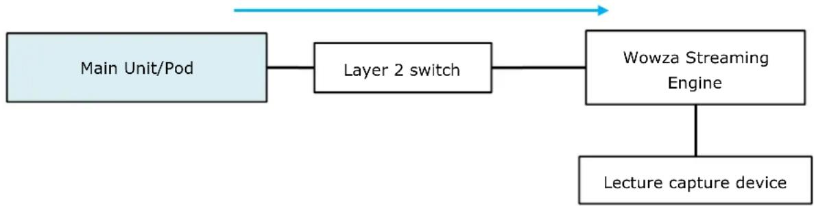
This section describes how to stream output using the Wowza Streaming Engine as the streaming output destination when connected without using RTSP.
The Wowza Streaming Engine is streaming engine software that receives a stream and distributes it to other devices.
flowchart
graph LR
    A["Main Unit/Pod"] --> B["Layer 2 switch"]
    B --> C["Wowza Streaming Engine"]
    C --> D["Lecture capture device"]
Set the following SDP (Session Description Protocol) in the Wowza Streaming Engine.
For details about configuration, refer to the instructions for the Wowza Streaming Engine.
The unit does not feature a function for sending SDP.
v=0
s=Vision Exchange Streaming Output
i=Vision Exchange Streaming Output
o=- 0 0 IN IP4 XXX.XXX.XXX.XXX
c=IN IP4 XXX.XXX.XXX.XXX
m=video 5004 RTP/AVP 105
a=rtpmap:105 H264/90000
m=audio 5006 RTP/AVP 98
a=rtpmap:98 mpeg4-generic/48000/2
a=fmtp:98
mode=AAC-hbr;profile-level-id=1;object=2;streamType=5;sizelength=13;indexlength=3;indexdeltalength=3;config=1190
a=ptime:20
Notes
- Enter the IP address of the Wowza Streaming Engine in XXX.XXX.XXX.XXX.
- The 5004 in "m=video 5004 RTP/AVP 105" is the port number of the video set on the main unit.
- The 5006 in "m=audio 5006 RTP/AVP 98" is the port number of the audio set on the main unit.
Connection and control using RTSP
To enable RTSP connections, on the [Setting] screen – [Streaming Output] page, place a check mark in [Enable RTSP Connection].
Also, specify the following streaming output URI in the application that will receive the stream. Specify settings using the configuration method of the application being used.
rtsp://host_name:port_number/media/video1
Enter the IP address of the main unit acting as the streaming output source for host_name. Enter the value set in [Setting] screen - [Streaming Output] page - [RTSP Port] for port_number. If the default value 554 of [RTSP Port] is left unchanged, the port number entry can be omitted.
Note
Digest authentication is an authentication method in which vulnerabilities have been found. Understand the risk of its use, and always use it on a secure network when possible.
Audio streaming
Select the audio for streaming from the following UI options on the [Setting] screen - [Streaming Output] page.
- Use speaker output as an audio streaming source
- Use microphone input as an audio streaming source
The data bit length and sample rate settings for audio streaming are set to Auto by default, and are configured automatically according to the selected audio streaming source above.
Note
Depending on the audio device connected to the selected audio streaming source, the Auto setting of audio streaming data bit length and sample rate may not work and there may be cases where audio is not output or noise is added to the audio.
In that case, this problem may be resolved by changing the following settings on the [Setting] screen - [Streaming Output] page.
Number of bits for audio streaming source: Selectable from Auto, 16bit, 24bit, 32bit.
Sample rate for audio streaming source: Selectable from Auto, 44100Hz, 48000Hz, 96000Hz, 192000Hz.
Network bandwidth
The video quality and throughput used for the video conferencing function is set on the [Setting] screen - [Streaming Output] page of the main unit.
For details about operation, refer to the Help Guide.
The configurable frame rates and throughput are given below.
Allow a margin of between 10% to 30% when calculating the network bandwidth as these values are empirical values only.
The actual throughput will vary depending on the subject.
Video
| Image quality | Display resolution | Frame rate (max.) Throughput (max.)(when playing video) |
| High | Same as main | 30 fps 6 Mbps |
| Middle 10 fps | sdis4 Mbopen | |
| Low 1 fps 1 | Mapsmitting device |
Audio
The maximum throughput is 128 kbps.
Plug-in Integration
You can expand the functionality using integration with external systems by installing plug-ins provided by various vendors on the main unit/Pods.
For details, contact the provider of the plug-in.
Notes
- If a plug-in uses a self-signed certificate, you must import that certificate for the main unit and Pods. For details about importing, refer to the manual for the plug-in and other resources such as the Microsoft website.
- Sony assumes no responsibility under any circumstances for damage, financial loss, or claims from any third-party resulting from the installation of malicious plug-ins.
- Sony assumes no responsibility under any circumstances for damage, financial loss, or claims from any third-party resulting from the reverse engineering of plug-ins.
- Plug-in configuration files are encrypted using AES-256 encryption, but there remains a risk of hacking. Sony assumes no responsibility under any circumstances for damage, financial loss, or claims from any third-party resulting from such activity.
Required Network Bandwidth for Comprehensive System
This section describes the network bandwidth required for constructing active learning and large-scale interactive lecture systems.
In an active learning system, it describes the three limitations on required network bandwidth for a system used for a combination of mirroring, Pod sharing, Skype for Business integration, and streaming output.
In an interactive lecture system, it describes the maximum limitations on required network bandwidth for a system used for a combination of mirroring, Personal Note Taker function, Skype for Business integration, and streaming output.
If the system also uses the Internet at the same time, extra bandwidth for Internet access also must be taken into consideration.
If joining an existing network, it is necessary to consider whether there is surplus bandwidth available for Vision Exchange from the existing bandwidth usage. If necessary, enhance the network infrastructure, for example by adding wireless LAN access points.
To generate a simple estimate of the network bandwidth, access the following website.
https://www.sonycreativesoftware.com/visionexchange/calc
Active learning
This section describes typical network bandwidth calculations when using three pods, six pods, and ten pods.
Small-scale 3-Pod configuration
Legend
Dotted arrow: Transfer using wired LAN or wireless LAN
Solid arrow: Transfer using wired LAN

flowchart
graph TD
    subgraph_Top_Dialog["Pod sharing (per stream)"]
        A["Pod 3"] --> B["Pod 2"]
        B --> C["Pod 1"]
        C --> D["(Eqn. A)"]
        D --> E["Main Unit"]
        E --> F["Main Display"]
        E --> G["Second Display"]
        D --> H["(Eqn. A)"]
        H --> I["Layer 2 switch"]
        I --> J["Mirroring to a Pod: 6 Mbps × 1 + 1 Mbps × 5 = 11 Mbps"]
        J --> K["Wireless LAN access point"]
        K --> L["(Eqn. A) × Number of Pods"]
    end

    subgraph_Bottom_Layer["User devices connected to Main Unit"]
        M["User device (1 device)"] --> N["User device (5 devices)"]
        O["User device (1 device)"] --> P["User device (5 devices)"]
        Q["User device (1 device)"] --> R["User device (5 devices)"]
        S["User device (2 devices)"] --> T["User device (4 devices)"]
        U["User devices connected to Pod 1"] --> V["User devices connected to Pod 2"]
        W["User devices connected to Pod 3"] --> X["User devices connected to Pod 3"]
    end

    style Top_Dialog fill:#f9f,stroke:#333
    style Bottom_Layer fill:#bbf,stroke:#333
This section describes how to calculate the required network bandwidth for a small-scale configuration using three Pods.
Determine the maximum number of simultaneous mirroring devices connected to the main unit and Pods beforehand as described in "Maximum number of simultaneous mirroring user devices" (page 21) in the "Active Learning" section.
Also, determine the image quality and throughput for mirroring, Pod sharing, Skype for Business integration, and streaming output beforehand as described in "Throughput when mirroring from a user device to the main unit/Pod" (page 14) in the "Small-Scale Interactive Lecture" section, "Pod sharing throughput between main unit and Pods" (page 24) in the "Active Learning" section, and "Network bandwidth" (page 44) in the "Streaming Output" section, respectively.
Next, calculate the network bandwidth that the wireless LAN access point and layer 2 switch must maintain.
This description is for a system with expanded number of Pods and Skype for Business integration, based on the example given in "Network bandwidth" (page 22) in the "Active Learning" section.
The proposed configuration is listed below.
- User devices connected to main unit or Pods: 6 (with image quality set to [High])
- Pods: 3
● Number of displays connected to the main unit: 2
● Bandwidth used by Skype for Business integration: 4 Mbps (Up), 4 Mbps (Down) - Streaming output: Image quality set to [High]
- Margin: 30%
For details about calculation equations, see "Network bandwidth" (page 22) in the "Active Learning" section.
Network bandwidth that the wireless LAN access point must maintain
Calculate the total throughput corresponding to the red and orange arrows in "Small-scale 3-Pod configuration" (page 46).
Calculation equation
Required bandwidth ( T_wlan ) = Total throughput of devices connected to each Pod (Eqn. A) ×
$$ \begin{array}{l} \text { Number of Pods } (N _ {\text { pod }}) \ + \text { Total throughput of user devices connected to main unit (Eqn.~A) } \ = (6 \mathrm{Mbps} \times 1 + 1 \mathrm{Mbps} \times 5) \times 3 \ + (6 \mathrm{Mbps} \times 2 + 1 \mathrm{Mbps} \times 4) \ \end{array} $$
$$ = 4 9 \mathrm{Mbps} $$
Adding the margin of 30%, 49 Mbps × 1.3 = 63.7 Mbps
Network bandwidth that must be maintained between each Pod and layer 2 switch
Calculate the total throughput corresponding to the red, blue, and green arrows for a Pod in "Small-scale 3-Pod configuration" (page 46).
Calculation equation
Required bandwidth ( T_pod ) = Total throughput from a wireless LAN access point to a Pod (Eqn. A)
- Throughput of content display Pod sharing from each Pod to the main unit (one blue arrow)
- Throughput for content display Pod sharing to each Pod from main unit (one green arrow)
= (6Mbps× 1 + 1Mbps× 5) - 6 Mbps
- 6 Mbps
= 23 Mbps
Adding the margin of 30%, 23 Mbps × 1.3 = 29.9 Mbps
Network bandwidth that must be maintained between main unit and layer 2 switch
Calculate the total throughput corresponding to the pink, blue, green, orange, and light blue arrows in "Small-scale 3-Pod configuration" (page 46).
Calculation equation
Required bandwidth ( T_main ) = Total throughput of user devices connected to main unit (Eqn. A)
- Total throughput from Pods to main unit (Eqn. B)
- Total throughput from main unit to Pods (Eqn. C)
- Total for Skype for Business integration (pink arrow)
- Streaming output (light blue arrow)
= (6Mbps× 2 + 1Mbps× 4) - (6 Mbps × 0 + 1 Mbps × 3)
- (6 Mbps × 3)
- (4 Mbps + 4 Mbps)
- 6 Mbps
= 51 Mbps
Adding the margin of 30%, 51 Mbps × 1.3 = 66.3 Mbps
Note that if a presentation is predominantly composed of still images, the throughput will be lower and hence the required bandwidth will also be lower. Estimate the network bandwidth to match the intended use.
Medium-scale 6-Pod configuration
This section describes how to calculate the required network bandwidth for a medium-scale configuration using six Pods.
In the same way as when using three Pods, determine the maximum number of simultaneous mirroring devices connected to the main unit and Pods beforehand as described in "Maximum number of simultaneous mirroring user devices" (page 21) in the "Active Learning" section. Next, calculate the network bandwidth that the wireless LAN access point and layer 2 switch must maintain.
The proposed configuration is listed below.
- User devices connected to main unit or Pods: 6 (with image quality set to [High])
- Pods: 6
● Number of displays connected to the main unit: 2
● Bandwidth used by Skype for Business integration: 4 Mbps (Up), 4 Mbps (Down) - Streaming output: Image quality set to [High]
- Margin: 30%
For details about calculation equations, see "Network bandwidth" (page 22) in the "Active Learning" section.
Network bandwidth that the wireless LAN access point must maintain
Calculation equation
Required bandwidth ( T_wlan ) = Total throughput of user devices connected to each Pod (Eqn. A)
$$ \begin{array}{l} \times \text { Number of Pods } \ + \text { Total throughput of user devices connected to main unit } (\text { Eqn. } A) \ = (6 \mathrm{Mbps} \times 1 + 1 \mathrm{Mbps} \times 5) \times 6 \ + (6 \mathrm{Mbps} \times 2 + 1 \mathrm{Mbps} \times 4) \ = 8 2 \mathrm{Mbps} \ \end{array} $$
Adding the margin of 30%, 82 Mbps × 1.3 = 106.6 Mbps
Network bandwidth that must be maintained between each Pod and layer 2 switch
See "Network bandwidth that must be maintained between each Pod and layer 2 switch" (page 48) in the "Small-scale 3-Pod configuration" section.
Network bandwidth that must be maintained between main unit and layer 2 switch Calculation equation
Required bandwidth ( T_main ) = Total throughput of user devices connected to main unit (Eqn. A)
$$ \begin{array}{l} + \text { Total throughput from Pods to main unit } (\text { Eqn. } B) \ + \text { Total throughput from main unit to Pods } (\text { Eqn. } C) \ + \text { Total for Skype for Business integration (pink arrow) } \ + \text { Streaming output (light blue arrow) } \ = (6 \mathrm{Mbps} \times 2 + 1 \mathrm{Mbps} \times 4) \ + (6 \text { Mbps } \times 0 + 1 \text { Mbps } \times 6) \ + (6 \mathrm{Mbps} \times 6) \ + (4 \mathrm{Mbps} + 4 \mathrm{Mbps}) \ + 6 \mathrm{Mbps} \ \end{array} $$
$$ = 7 2 \mathrm{Mbps} $$
Adding the margin of 30%, 72 Mbps × 1.3 = 93.6 Mbps
Note that if a presentation is predominantly composed of still images, the throughput will be lower and hence the required bandwidth will also be lower. Estimate the network bandwidth to match the intended use.
Large-scale 10-Pod configuration
This section describes how to calculate the required network bandwidth for a large-scale configuration using ten Pods.
In the same way as when using three Pods, determine the maximum number of simultaneous mirroring devices connected to the main unit and Pods beforehand as described in "Maximum number of simultaneous mirroring user devices" (page 21) in the "Active Learning" section.
Next, calculate the network bandwidth that the wireless LAN access point and layer 2 switch must maintain.
The proposed configuration is listed below.
- User devices connected to main unit or Pods: 6 (with image quality set to [High])
- Pods: 10
● Number of displays connected to the main unit: 2
● Bandwidth used by Skype for Business integration: 4 Mbps (Up), 4 Mbps (Down) - Streaming output: Image quality set to [High]
- Margin: 30%
For details about calculation equations, see "Network bandwidth" (page 22) in the "Active Learning" section.
Network bandwidth that the wireless LAN access point must maintain
Calculation equation
Required bandwidth ( T_wlan ) = Total throughput of user devices connected to each Pod (Eqn. A)
$$ \begin{array}{l} \times \text { Number of Pods } \ + \text { Total throughput of user devices connected to main unit } (\text { Eqn. } A) \ = (6 \mathrm{Mbps} \times 1 + 1 \mathrm{Mbps} \times 5) \times 1 0 \ + (6 \mathrm{Mbps} \times 2 + 1 \mathrm{Mbps} \times 4) \ = 1 2 6 \mathrm{Mbps} \ \end{array} $$
Adding the margin of 30%, 126 Mbps × 1.3 = 163.8 Mbps
Network bandwidth that must be maintained between each Pod and layer 2 switch
See "Network bandwidth that must be maintained between each Pod and layer 2 switch" (page 48) in the "Small-scale 3-Pod configuration" section.
Network bandwidth that must be maintained between main unit and layer 2 switch Calculation equation
Required bandwidth ( T_main ) = Total throughput of user devices connected to main unit (Eqn. A)
- Total throughput from Pods to main unit (Eqn. B)
- Total throughput from main unit to Pods (Eqn. C)
- Total for Skype for Business integration (pink arrow)
- Streaming output (light blue arrow) = (6 Mbps × 2 + 1 Mbps × 4)
- (6 Mbps × 0 + 1 Mbps × 10)
- (6 Mbps × 10)
- (4 Mbps + 4 Mbps)
- 6 Mbps = 100 Mbps
Adding the margin of 30%, 100 Mbps × 1.3 = 130 Mbps
Note that if a presentation is predominantly composed of still images, the throughput will be lower and hence the required bandwidth will also be lower. Estimate the network bandwidth to match the intended use.
Note
If using streaming output or Skype for Business or both in a maximum configuration, the content display performance may be reduced. It is recommended that limits be placed on the connected devices or the use of certain functions (for example, on the number of HDMI inputs or the number of whiteboards) as required.
Also, there is a possibility that the frame rate of video content may be reduced and delay may increase, depending on the combination of the number of Pods sharing, the number of HDMI inputs, the number of whiteboards, the number of devices mirroring, the Skype for Business/Zoom function, streaming output, and other functions. Therefore, it is necessary to design a system that considers performance, not limited to the maximum configuration.

flowchart
graph TD
    A["Pod server"] --> B["Layer 2 switch"]
    B --> C["Wireless LAN access point"]
    C --> D["User device (100 devices)"]
    D --> E["User devices using Personal Note Taker"]
    E --> F["User device (2 devices)"]
    E --> G["User device (4 devices)"]
    H["Main Display"] --> I["Skype for Business integration: Ex: 4 Mbps (Up), 4 Mbps (Down)"]
    I --> J["Streaming output: 6 Mbps"]
    K["Second Display"] --> L["(Eqn. A)"]
    M["Personal Note Taker: 6.4 Mbps (max.) × 100"] --> N["User device (100 devices)"]
    O["Mirroring to main unit: 6 Mbps × 2 + 1 Mbps × 4 = 16 Mbps"] --> P["User devices for mirroring"]
The following describes how to calculate the required network bandwidth for a large-scale configuration comprising 6 mirroring user devices and 100 user devices using the Personal Note Taker function.
Determine the maximum number of simultaneously connected user devices used for mirroring and the Personal Note Taker function beforehand as described in "Maximum number of simultaneous mirroring user devices" (page 31) and "Maximum number of simultaneous user devices for Personal Note Taker function" (page 31) in the "Large-Scale Interactive Lecture" section.
Also, determine the image quality and throughput for mirroring, Personal Note Taker function, Skype for Business integration, and streaming output beforehand as described in "Network bandwidth" (page 32) in the "Large-Scale Interactive Lecture" section, "Network bandwidth" (page 39) in the "Skype for Business Integration" section, and "Network bandwidth" (page 44) in the "Streaming Output" section.
Next, calculate the network bandwidth that the wireless LAN access point and layer 2 switch must maintain.
This description is for a system with added Skype for Business and streaming output, based on the example given in "Network bandwidth" (page 32) in the "Large-Scale Interactive Lecture" section.
The proposed configuration is listed below.
- User devices mirroring: 6 (with image quality set to [High])
- User devices using Personal Note Taker function: 100 (with image quality set to [High])
● Number of displays connected to the Pod server: 2
● Bandwidth used by Skype for Business integration: 4 Mbps (Up), 4 Mbps (Down) - Streaming output: Image quality set to [High]
- Margin: 30%
For details about calculation equations, see "Network bandwidth" (page 32) in the "Large-Scale Interactive Lecture" section.
Network bandwidth that the wireless LAN access point must maintain
Calculate the total throughput corresponding to the orange and purple arrows in the preceding diagram.
Calculation equation
$$ \begin{array}{l} \text { Required bandwidth } (T _ {\text { wlan }}) = \text { Total throughput of user devices for mirroring } (\text { Eqn. A }) \ + \text { Total throughput of user devices using Personal Note Taker function (purple arrow) } \ = (6 \text { Mbps } \times 2 + 1 \text { Mbps } \times 4) \ + (6. 4 \mathrm{Mbps} \times 1 0 0) \ = 6 5 6 \mathrm{Mbps} \ \end{array} $$
Adding the margin of 30%, 656 Mbps × 1.3 = 852 Mbps
Network bandwidth that must be maintained between Pod server and layer 2 switch
Calculate the total throughput corresponding to the orange, purple, pink, and light blue arrows in the preceding diagram.
Calculation equation
Required bandwidth ( T_main ) = Total throughput of user devices for mirroring (Eqn. A) + Total throughput of user devices using Personal Note Taker function (purple arrow) + Total for Skype for Business integration (pink arrow) + Streaming output (light blue arrow) = (6 Mbps × 2 + 1 Mbps × 4) + (6.4 Mbps × 100) + (4 Mbps + 4 Mbps) + 6 Mbps = 670 Mbps
Adding the margin of 30%, 670 Mbps × 1.3 = 871 Mbps
If joining an existing network, it is necessary to consider whether there is surplus bandwidth available for Vision Exchange from the existing bandwidth usage. If necessary, enhance the network infrastructure, for example by adding wireless LAN access points.
If the required network bandwidth cannot be maintained, reduce the number of simultaneous connections, or set the image quality to Mid or Low to reduce the bandwidth usage for Vision Exchange. Note that the resulting picture will be degraded if the image quality setting is reduced.
Note that if a presentation is predominantly composed of still images, the throughput will be lower and hence the required bandwidth will also be lower. Estimate the network bandwidth to match the intended use.
4. Installation and Setup
This section describes an overview of the procedures for setting up the main unit and Pods using Windows 10.
For details, procedures, and operation of Windows Server on a Pod server, refer to the Windows Server manuals or visit the Microsoft website.
Supplied Items and Optional Items
Supplied items
The following items are supplied with the unit.
| Items supplied with main unit Description | |
| Main Unit The main unit is available in two types. | PEQ-C100: Has two HDMI input connectorsPEQ-C130: Has four HDMI input connectors |
| AC adapter | |
| Power cord Available separately in some countries/regions. | |
| Attachment bracket and screws for power cord | |
| Initial SUP license purchase key certificate | Bundled with the accessories in the carton. |
SUP (Software Upgrade Program)
SUP provides a license that can be used to update the Vision Exchange software.
Subscribing to SUP allows you to receive new functionality, improvements and features, continuous support for user devices and other benefits.
When purchasing Vision Exchange, a complementary free 1-year SUP subscription is bundled with the unit.
For details for subscribing to SUP in year 2 and subsequent years, contact your sales representative.
| Name Model Description | ||
| SUP for main unit | PEQ-C1SU | SUP for the main unit (1-year subscription). |
| SUP for Pod PC Software | PES-C1SU | SUP for Pod PC Software (1-year subscription). |
Option software and licenses
Option functions can be used without limitations by purchasing an option software license and activating the license on the main unit or a Pod. Convenient software that can be installed on user devices is also available.
About license trials
If an option function is used without activation of a license, a notification dialog box will appear when first started. Subsequently, the option function can be used without limitation for a period of 3 minutes only. After 3 minutes have elapsed, the connection using the corresponding option function will be disconnected automatically.
| Type Name | Model Description | |||
| License for main unit/Pod | Streaming Output License | PEQA-C30 License to enable the streaming output function. | ||
| License for main unit | Active Learning License | PEQA-C10 License to enable the Pod sharing function. | ||
| Pod PC Software and software license | Pod PC Software PES-C10 License to activate Pod PC Software.There are no limitations on downloading and installing this software, but a Pod PC Software license purchase and entry of an installation key is required to use the software. | |||
| Type Name Model Description | ||||
| User device software | Vision Exchange App. | - This software is for installation on user devices to enable participation with Vision Exchange.Allows you to mirror the display of a user device on the main unit or a Pod, and to control the main unit or a Pod from a user device.The software can be downloaded for free from the following URL. For details about the devices supported for installation of this software, visit the following URL.http://www.sony.com/VEapp | ||
Required/Recommended Specifications of Items Available Separately
Pod
Prepare a computer with the following specifications for connecting user devices and the main unit. The computer is used as a "Pod" in the system by installing Pod PC Software.
Note
In some countries/regions, the supply of Pod PC Software by itself may not be available from a product support point of view. For details, contact your sales representative.
There are two types of computer specifications according to the functions used.
● Basic collaboration
Supports Vision Exchange version 1.0 functions.
The main functions include content switching, mirroring, annotation/whiteboard, and snapshot/download functions.
- Full collaboration
Supports Vision Exchange version 1.1 functions.
In addition to the version 1.0 functions, this version also supports Skype for Business integration, HDMI input, streaming output, and the Personal Note Taker function.
A computer with higher specifications than that for basic collaboration is required.
Note
Do not use a device in which the computer and a display or touch panel are integrated (such as a notebook computer). The functions of that device and the Vision Exchange functions may conflict and may not operate correctly.
Required specifications
Pod PC Software will not run correctly on a computer that does not meet the following specifications.
For full collaboration, select either a mini PC type or desktop PC type computer.
| Basic collaboration | Full collaboration | ||
| Mini PC type | Desktop PC type | ||
| CPU 6th generation Intel®CoreTM i5-6260U(1.8 GHz, 4 MB cache,2 cores, 4 threads, IntelIris graphics) or higher | 6th generation Intel®CoreTM i7-6770HQ or higher | 8th generation Intel®CoreTM i5-8600K or higherIntegrated Intel Graphics (QSV support) | |
| Memory Rating: DDR4-2133 or higherCapacity: 4 GB (or higher) × 2Dual channels with same rating and capacity (a single 8 GB DIMM is not recommended as it has lower performance than two 4 GB DIMMs) | |||
| Storage SSD: 128 GB, 6 Gbps or higherRAID configuration is not supported. | |||
| OS Windows | 10 Pro 64-bit Anniversary Update (version 1607) or later | ||
| OSlanguage | EnglishIt is possible to change the default input language to a language other than English. | ||
| Graphics Intel Graphics Driver version: 21.20.16.4627 or laterThe first six digits of the version number vary depending on the Intel or Microsoft version schema. The last four digits indicate the build number of the Intel Graphics Driver.To check and update the version, check the documentation that came with the computer, the Microsoft or Intel website, or contact the computer manufacturer.NoteDo not use a computer equipped with a GPU other than Intel Graphics (such as NVIDIA). There is a risk that the system will not operate correctly. | |||
| LAN 10/100/ | 1000 Mbps or faster ethernet (RJ-45) | ||
| USB | USB 3.0 | ||
Full collaboration function support on computer for basic collaboration
Example support ranges are shown in the following table for reference.
Patterns A to D have been verified for interactive lectures.
The values in the table indicate the number of user devices or functions that can be used simultaneously.
| Function | Active Learning | Interactive Lecture | |||
| A B C D | |||||
| Display (number of video output connectors) | 1 | 2 | 2 | 2 | 2 |
| Whiteboard 4 | 4 | 4 | 4 | 4 | |
| Mirroring 6 | 6 | 6 | 6 | 6 | |
| Personal Note Taker function No | 14 14 14 No | ||||
| HDMI input | OK | OK | No | No | OK |
| Skype for Business integration | No | No | OK | No | OK |
| Streaming output | OK | No | No | OK | |
* Main unit: 2 displays, 4 whiteboards, 2 mirroring devices, 4 HDMI inputs, 10 pods, Skype for Business integration support, and streaming output support
OK
Installing Pod PC Software
Follow the procedure described in "Preparation Before Installation" (page 62) to install the software.
Pod server
In "Large-Scale Interactive Lecture" (page 27) in the "Configuration Examples for Various Use Cases" section, content is distributed to the web browsers of 21 to 100 participants.
Prepare a computer with the following specifications to operate the system described in "Large-Scale Interactive Lecture" (page 27).
Construct a Pod server by installing Pod PC Software on the computer.
Note
In some countries/regions, the supply of Pod PC Software by itself may not be available from a product support point of view. For details, contact your sales representative.
Required specifications
Pod PC Software will not run correctly on a computer that does not meet the following specifications.
Operation under the following conditions has been verified on an HPE DL360 Gen10 equipped with NVIDIA Quadro P2000 graphics board.
| Pod server | |
| CPU CPU: Intel® Xeon® Silver 4110 processor or later | |
| Memory Rating: DDR4-2133 or higherCapacity: 4 GB (or higher) × 2Dual channels with same rating and capacity (a single 8 GB DIMM is not recommended as it has lower performance than two 4 GB DIMMs) | |
| Storage SSD: 128 GB, 6 Gbps or higherRAID configuration is not supported (SATA AHCI mode is supported). | |
| OS Windows Server 2016 Standard | |
| OS language EnglishIt is possible to change the default input language to a language other than English. | |
| Graphics NVIDIA Quadro P2000 or higher | |
| LAN 10/100/1000 Mbps or faster ethernet (RJ-45) | |
| USB | USB 3.0 |
| Miscellaneous | ● Sound card or USB audio device that supports 16-bit quantization, 48 kHz sampling frequency, 2-channel PCM● Windows Server Client Access License (CAL): Prepare the appropriate version, type, and number of licenses according to the type of users. For details, visit the following website or contact Microsoft. https://www.microsoft.com/en-us/licensing/product-licensing/client-access-license.aspx |
Installing Pod PC Software
Follow the procedure described in "Preparation Before Installation" (page 62) to install the software.
HDMI capture box
Prepare the following box for capturing the HDMI output from a laptop computer or camera and importing into a Pod via USB 3.0.
DarkCrystal 750 (model name: CD750)
https://www.avermedia.com/professional/product/cd750/overview
HDMI 1.3 compatible
Visit the website above for other specifications (such as supported resolution, frame rate, audio).
Notes
- Use the dedicated Vision Exchange device driver included in Pod PC Software as the device driver for the HDMI capture box. Correct operation using the AVerMedia standard device driver, which can be obtained from the AVerMedia website, is not guaranteed, and its use may cause a malfunction. Do not install this driver.
- User the USB 3.0 cable supplied with the HDMI capture box for connection with a Pod. Correct operation using other USB cables is not guaranteed.
- HDCP is not supported.
- Only one HDMI capture box can be connected to a single Pod. Also, do not connect it to the main unit.
User device
For details about recommended specifications for devices to connect to the main unit or Pods, refer to the Help Guide.
Wireless LAN network and access points
Recommended specifications
Access point products
Use an access point designed for business use.
* Access point products for home use are not recommended due to their low throughput when connected with multiple user devices simultaneously.
Frequency band
5 GHz band
* The 2.4 GHz band is not recommended due to the increased possibility of radio wave interference from devices, such as microwave ovens and Bluetooth devices.
Preparation Before Installation
The required equipment will vary depending on the system application and configuration. Refer to the system configuration examples when designing your system.
Prepare equipment not supplied (see next section) separately.
To use a main unit and Pods, online registration in SUP (Software Upgrade Program) on the Internet when purchasing products and acquisition of installation keys for the main unit and Pod PC Software may be required.
For details about SUP, see "SUP (Software Upgrade Program)" (page 55).
Option software may be required depending on the functions to be used. A license purchase key and option software installation key must be obtained in order to use option software.
Note
In some countries and regions, SUP registration and issuing of keys online may not be available. In that case, do it offline.
The following describes the basic procedure for registering and obtaining licenses. For details, contact your sales representative.
Also, refer to the Help Guide.
Installing Pod software
Use the following procedure to install Pod PC Software on a Pod PC.
Access the following URL in a web browser, and download the Pod PC Software installer.
http://www.sony.com/VESW
Pods can be used in either Vision Exchange dedicated mode or Windows desktop application mode formats.
Configure the OS (including the domain settings) beforehand to make sure the screen does not become locked during installation or operation.
Also, make sure you have the required permissions for installing and operating Pod PC Software. Check the settings beforehand. For details, see "Checking permissions and settings" (page 65).
You can also change modes after starting operation from the Administrator screen. For details, refer to the Help Guide.
Vision Exchange dedicated mode
In this mode, Vision Exchange automatically starts when the Pod PC starts.
To use Vision Exchange dedicated mode, launch the downloaded installer as an administrator and follow the installer procedure to install the software on each Pod PC. Entry of an installation key is required after installation. Details about obtaining an installation key are described in the following section.
Windows desktop application mode
If you want to participate using a Pod PC within a domain, such as an organization, use the following procedure to use Vision Exchange in Windows desktop application mode on the Pod PC.
However, this function is intended for domain participants only, and is not intended for installing third-party applications and using as a general Windows PC.
- Log in as an administrator user, and run the installer as an administrator.
- Clear the check mark from "Set this PC as a dedicated device for Vision Exchange" and follow the installer instructions.
Entry of an installation key is required after installation. Details about obtaining an installation key are described in the following section.
Notes
- You may encounter trouble immediately after the release of large Windows updates. Until a revised Vision Exchange version is released, Vision Exchange may not operate. It is recommended that you postpone major updates (by up to one year) and only update for vulnerability issues.
Configure the settings within each operating system in order to defer large-scale updates.
- To start Vision Exchange in Windows desktop application mode, you must use the shortcut placed on the desktop after installation or use the Windows menu.
Unlike Vision Exchange dedicated mode, Vision Exchange does not start automatically when the Pod PC starts. To enable Vision Exchange auto startup when logging in to Windows, manually register the application in the startup items. It may take some time for Vision Exchange to start when launched as a startup item.
- When Vision Exchange is run in Windows desktop application mode, the update and log export functions cannot be used when the application is started with user permissions. It must be run as an administrator in order to use the maintenance functions.
However, when you run Vision Exchange in Windows desktop application mode as an administrator, a warning dialog is displayed prompting you whether or not to continue using Vision Exchange. If you press [Continue] in the dialog, restrictions applied to the integration function with Skype for Business disable the Skype for Business function.
- To use Windows desktop application mode, grant OS shutdown permission to the Vision Exchange startup account. If permission is not granted, the Vision Exchange shutdown processing will not be executed successfully.
- The Pod PC Software installer does not support overwrite installation. Overwrite installation may cause Vision Exchange to malfunction. If Vision Exchange must be reinstalled for any reason, start from reinstalling the OS. Also, when updating Pod PC software, always update using [Online Update] or [Offline Update], without using the installer.
- Pod PC Software does not support 4K resolution. Set an HD resolution, such as 1920 × 1080 , including during installation.
Open the control panel and local group policy editor of the OS, and check that the required permissions and conditions are satisfied. If not, configure the necessary items.
| Vision Exchange dedicated mode | Windows desktop application mode | |
| When installing/updating | Shutdown permission is requiredScreen unlocking permission is requiredAuto startup configuration permission is requiredPassword expiration date is an indefinite periodPassword change request is configured when logging in for the first timeFirewall configuration permission is requiredEnvironment variable addition permission is requiredWindows Service registration and configuration permission is requiredPower policy settings configuration permission is requiredCertificate addition permission is requiredCOM registration permission is requiredGAC (Global Assembly Cache) registration permission is requiredRegistry write/modify permission is requiredWindows feature activation permission is requiredRestore point activation permission is requiredUAC settings modify permission is requiredEvent log write permission is required | Shutdown permission is requiredScreen unlocking permission is requiredFirewall configuration permission is requiredEnvironment variable addition permission is requiredWindows Service registration and configuration permission is requiredPower policy settings configuration permission is requiredCertificate addition permission is requiredCOM registration permission is requiredRegistry write/modify permission is requiredWindows feature activation permission is requiredRestore point activation permission is requiredUAC settings modify permission is requiredEvent log write permission is required |
| When operating | Shutdown permission is requiredScreen unlocking permission is requiredAuto startup configuration permission is requiredPassword expiration date is an indefinite periodRegistry write/modify permission is requiredEvent log write permission is required | Screen unlocking permission is requiredRegistry write/modify permission is requiredEvent log write permission is required |
Registering in SUP and obtaining installation keys for a main unit/Pod
- Order products from your Sony sales representative or dealers to obtain a SUP purchase code.
The SUP purchase code delivery (mail attachment, post, or fax) may vary depending on the region.
- Check the Device Unique ID of purchased main unit and Pod PC Software.
On the main unit
The Device Unique ID is on the barcode label attached to the carton. Also, launch Vision Exchange, open the [Administrator Menu] – [License] page from the Home screen and check the Device Unique ID.
On a Pod
Start the Pod PC, and check the Device Unique ID on the startup screen.
- Register in SUP online, and obtain an installation key.
Access "Upgrade and License Management Suite" at the following URL in a web browser to register in SUP and obtain an installation key using the product SUP purchase code and Device Unique ID.
https://ulms.sony.net
For details about SUP registration, visit the following URL.
https://pro.sony/en_GB/product-resources/knowledge-panel/vision-exchange-software-upgrade-program
- Enter the installation key on the main unit or Pods to activate them.
On the main unit
Turning on the main unit which has not yet been activated will display the installation key input screen.
On a Pod
An installation key input screen will be displayed during Pod PC Software installation.
The main unit or Pods are enabled for use.
Registering option software and obtaining an installation key
- Order licenses for option software from your Sony sales representative or dealers to obtain a license purchase key.
The license purchase key delivery (mail attachment, post, or fax) may vary depending on the region.
Note
When purchasing an Active Learning license, a Device Unique ID is required for each Pod.
Start the Pod PC on which you installed Pod PC Software, and check the Device Unique ID on the startup screen.
- Check the Device Unique ID of the main unit or Pods on which you want to install a license.
On the main unit
The Device Unique ID is on the barcode label attached to the carton. Also, launch Vision Exchange, open the [Administrator Menu] – [License] page from the Home screen and check the Device Unique ID.
On a Pod
Start the Pod PC, and check the Device Unique ID on the startup screen.
- Register the license purchase key and Device Unique ID online to obtain an installation key.
Access the "Upgrade and License Management Suite" (see URL below), and register the license purchase key and the Device Unique ID of the main unit or Pods on which you want to install a license.
https://ulms.sony.net
An installation key is issued within a few minutes.
- From the Home screen of the main unit or Pod, open the [License] page of [Administrator Menu], and enter the installation key to activate the license.
Activation enables use of the option software.
Notes
- When registering a license purchase key, you can issue an installation key for as many licenses as you have purchased.
- The installation key is linked to the Device Unique ID of the Pod. When issuing an installation key, always enter the Device Unique ID of the Pod to activate.
- If the Device Unique ID used when issuing the installation key differs from the Device Unique ID of the Pod on which the installation key is entered, license activation will fail.
- If Pod PC Software is installed on another computer, due to Pod malfunction or failure, the installation key must be reissued. Contact your Sony sales representative or dealer.
Installing Third-Party Software
Whitelisting type antivirus software is installed in the main unit.
Accordingly, software installed without using the following procedure will not function.
Notes
- Use of third-party device connections and third-party device drivers/applications are not covered by the Vision Exchange operational guarantee.
- The use of third-party device drivers and applications may adversely affect the performance and operation. Verify correct operation sufficiently before use. Installation is the responsibility of the system administrator.
- Support is not offered for cases where third-party device drivers/applications cannot be installed or where third-party connected devices do not operate.
Third-party device drivers and applications
Device drivers must be installed separately for touch panel displays and other devices whose connection is not recognized by the Windows standard driver. Prepare a dedicated device driver or a device driver with installer from the manufacturer of devices to connect, and install using the following procedure.
- Log in as the OS administrator.
- On the main unit, run Maintenance.exe from the desktop. On a Pod, launch Command Prompt from the Windows menu.
Command Prompt launches. - Install the device driver or run the installer using the Command Prompt commands. For details, refer to the manuals of the device to connect and the device driver/application.
Installation/Usage Precautions
Main Unit
When installing, ensure that there is sufficient space for ventilation and service tasks.
- Do not install in an unstable location.
- Do not install in a location that is subject to rain, oil smoke, steam, moisture, or dust.
- Do not block the ventilation openings.
- Do not push into an enclosed narrow space.
- Do not wrap with cloth.
- Do not topple sideways.
- Do not stack.
- Install on a level surface.
About rack mounting
- While screw holes are provided on the bottom of the unit for mounting, it is not a rack-mount recommended device.
- If using the screw holes, always mount in a rack or cabinet that can support the weight of the unit (approx. 3.4 kg (7 lb 8 oz)).
Hole locations on bottom of unit
- There are four screw hole locations. The holes are for M3×15 screws.

Usage precautions
- The guaranteed time for continuous operation is 23 hours. Usage should be less than 23 hours in duration in principle.
- Set the date and time. Some functions may not operate if the date and time are not set correctly. The date and time can be set automatically using a network time server or be set manually. For details, refer to the Help Guide.
- Run "Software Update" when launching for the first time. For details, see "Software Update" (page 87) in the "Service and Maintenance" section.
● Always use the latest version of software.
Correct operation of the main unit when connecting and disconnecting cables, excluding the HDMI input connector, during operation is not guaranteed.
If you inadvertently disconnect a cable, reconnect the cable and then reboot the main unit.
Before connecting or disconnecting cables, make sure that the power supply is first turned off.
Main display, second display, touch panel
Two displays can be connected. The second display can display a different extended image than the first display.
For example, different presentations can be shown on the two displays to support large-scale lectures or meetings.
Also, a second HDMI display can be connected when a DisplayPort-to-HDMI adapter is connected to the DISPLAY PORT connector.
Notes
- Daisy chain connections using the DisplayPort Multi Stream Transport (MST) function are not supported.
- The cursor may not be displayed correctly if a touch panel and mouse are used together. Except for maintenance, do not use a touch panel and mouse at the same time.
- VGA connectors cannot be used.
Assigning the main display and second display
- Connect two displays to the main unit.
- Turn on the devices.
- Open the [Display] page of the [Setting] screen.
- Select [Extend these displays] or [Clone these displays] in [Multiple Displays].
-
Select the primary display in [Display], and set the following items.
[Resolution]
Select the resolution of the selected display.
[Location]
Select the [Left] / [Right] location of the selected display.
[Make this my main display]
Place a check mark here to set the selected display as the main display. -
Select the secondary display in [Display], and set the following items in the same way as for the primary display.
[Location] is automatically set to the opposite value of the primary display.
Touch panel display connection (USB connection)
A USB type touch panel can be connected to a display. A touch panel allows the presenter to conduct a smooth dynamic session by simply swiping on the screen to switch the displayed image.
To connect a touch panel display, in addition to the HDMI connector or DISPLAY PORT connector connection for sending video, it must also be connected via USB to transmit touch gesture controls.
Connect the main unit and the display using a USB cable.
To connect two touch panel displays, assign the touch panels to be the main display and second display using the following procedure.
- Connect the main unit to each display using a display cable and USB cable.
- Turn on the devices.
- Log in as the OS administrator.
- Open [Control Panel] - [Hardware and Sound] - [Tablet PC Settings].
Note
If [Tablet PC Settings] is not displayed, check the USB cable connection of the touch panel display, then do step 4 again.
- Click [Setup] on the [Display] tab of the [Tablet PC Settings] window.
- Follow the on-screen instructions to configure the main display and second display touch panel assignments.
- Click [Calibrate] on the [Display] tab of the [Tablet PC Settings] window.
- Follow the on-screen instructions to adjust the touch panel range for the main display and second display.
Third-party device driver installation
Device drivers must be installed separately for touch panel displays and other devices whose connection is not recognized by the Windows standard driver.
For details, see "Third-party device drivers and applications" (page 68) in the "Installing Third-Party Software" section.
Pod
Connect between the main unit and Pods using wired LAN network connections.
Notes
- Enable only one Ethernet setting in [Network Connections] in the [Control Panel]. Disable Wi-Fi, Bluetooth, and other networks.
- Correct operation is not guaranteed when connecting and disconnecting cables during Pod operation. Before connecting or disconnecting cables, make sure that the Pod power supply is first turned off. If you inadvertently disconnect a cable during Pod operation, reconnect the cable and then reboot the Pod.
- If the network connection between the main unit and a Pod is disconnected for a certain period of time due to a network failure, the connection between the main unit and the Pod may not be restored correctly even after the network is restored in rare cases. In this case, try rebooting the main unit and Pod.
For details about the computer setup procedure, refer to the manual supplied with the computer.
For details about operation of Pod PC Software, refer to the Help Guide.
HDMI capture box
Use the following procedure on a Pod on which Pod PC Software has been activated.
- Connect the USB 3.0 cable supplied with the HDMI capture box between the HDMI capture box and the USB 3.0 port on the Pod.
- Connect the HDMI cable between the HDMI input connector on the HDMI capture box and the the HDMI output device.
- Turn on the Pod.
The HDMI input function becomes enabled.
The HDMI cable can be disconnected and reconnected during Pod operation.
Note
Correct operation is not guaranteed when connecting and disconnecting USB cables during Pod operation. If you inadvertently disconnect a USB cable, reconnect the USB cable and then reboot the computer. Before connecting or disconnecting cables, make sure that the power supply is first turned off.
Notes on Designing the Video System
Deinterlacing
If moving images are input/played back from HDMI input and thin horizontal stripes appear in the image, you can make the video be played clearly by enabling deinterlacing.
However, this function may cause distortion of small text characters in still images or adversely affect the image quality. To display still images with small graphs and text characters clearly, disable this function.
If the motion in images from an HDMI input is more important, enable deinterlacing. To prioritize image quality, disable deinterlacing. For details about configuration, refer to the Help Guide.
Video frame rate and user interface response speed
On the main unit or a Pod, the video frame rate may be reduced or the user interface (whiteboard or drawing annotations) response speed may become slower when using the following functions due to system load limitations.
- When two displays are connected to the main unit or Pod. To prioritize the video frame rate, connect only one display.
- The Personal Note Taker function is enabled on the main unit or Pod. To prioritize the video frame rate, disable this function.
- Streaming output is enabled on the main unit. To prioritize the video frame rate, disable this function.
- A 4K compatible display is connected. To prioritize the video frame rate, reduce the display resolution. The recommended resolution is 1920 × 1080 or other HD resolution.
-
The main unit supports the following connections, although the video frame rate may be reduced, the user interface (whiteboard or drawing annotations) response speed may become slower, or annotations may not be possible if all are used at the same time.
-
HDMI inputs: Up to 4 devices (PEQ-C100: up to 2 devices)
- Mirroring: Up to 6 devices
- Remote control from Vision Exchange App or Personal Note Taker function: Up to 4 devices
- Pods: Up to 10 devices
- Display output: Up to 2 devices
- SRG-120DU
- Skype for Business integration
- Streaming output
- Whiteboards on main unit: Up to 4 created and displayed
* To give priority to video frame and user interface response speed or to give priority to annotations, reduce the number of mirrored devices by 4 to two devices.
- The performance may be adversely affected if Windows Update executes automatically. First check if Windows Update is enabled. If enabled, set Windows Update to execute at times when the main unit or a computer on which Pod PC Software is installed are not in use.
- The main unit supports HDCP. HDCP content from devices connected to the HDMI input connectors on the rear panel of the main unit can be played. On the [Setting] screen – [HDMI Input] page, place a check mark in [Enable HDCP] to view HDCP content on a display. For details, refer to the Help Guide.
- When a Mac with an HDMI output connector is connected to the HDMI input connector of the main unit, place a check mark in [Setting] screen – [HDMI] page – [Enable HDCP].
- If a repeater device is connected to the HDMI output and DisplayPort output of the main unit, HDCP content cannot be played. A black screen is displayed.
- If a switcher, splitter, or converter is inserted between the HDMI input of the main unit and the HDMI (HDCP) source device, the HDCP content may not be displayed properly. Test the device beforehand before use.
-
HDCP content cannot be played back while using the following functions. A black screen is displayed.
-
Pod sharing
– Sharing content with remote parties when using Skype for Business - Streaming output
- Personal Note Taker function
Notes on Designing the Audio System
The unit has an array of audio inputs/outputs for connecting to network systems and various devices. This section provides an overview of the audio systems supported by the unit.
| Name of input/output in diagram | Direction | Description |
| HDMI IN 1 Input Audio from | HDMI IN 1 | connector |
| HDMI IN 2 Input Audio from | HDMI IN 2 | connector |
| HDMI IN 3 Input Audio from | HDMI IN 3 | connector(Not available on the PEQ-C100) |
| HDMI IN 4 Input Audio from | HDMI IN 4 | connector(Not available on the PEQ-C100) |
| MIRRORING IN | Input | Audio when mirroring from a user device |
| Skype for Business IN Input | Audio received from remote party during Skype for Business integration | |
| MIC IN Input Audio from MIC-IN connector | ||
| USB AUDIO IN | Input | Audio input from a connected USB audio device |
| LINE IN Input Audio from LINE-IN connector | ||
| HDMI OUT Output Audio on the HDMI OUT connector | ||
| DISPLAY PORT OUT Output | Audio on the LINE-OUT | DISPLAY PORT connector |
| LINE OUT Output Audio on the LINE-OUT | connector | |
| USB AUDIO OUT | Output | Audio output of a connected USB audio device |
| STREAMING OUT | Output | Audio streamed when using the streaming function |
| Skype for Business OUT | Output | Audio sent to remote party during Skype for Business integration |
The input/output selection is in [Administrator Menu] – [Setting]. Set each setting as shown in the following diagram.
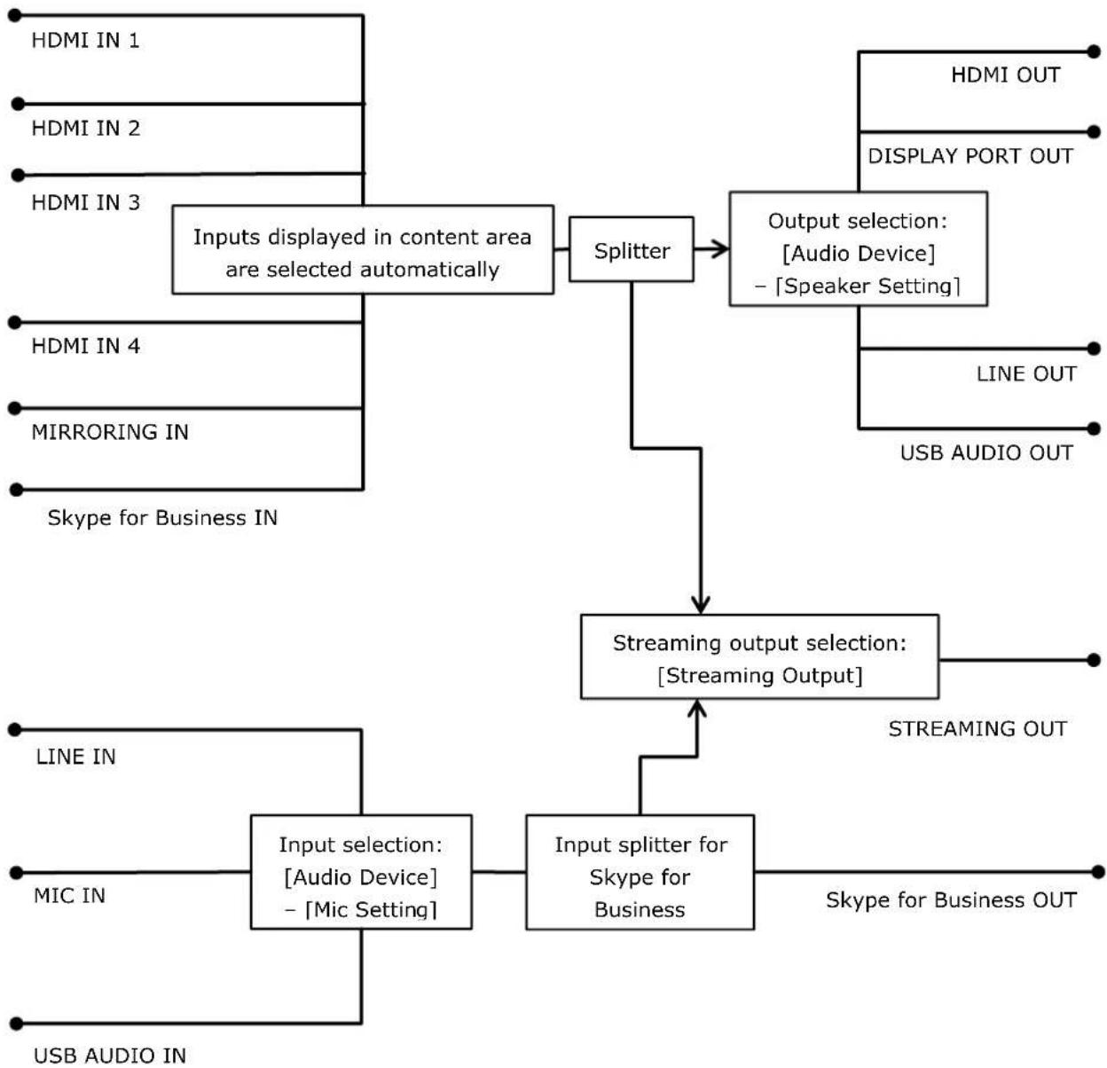
flowchart
graph TD
    A["Inputs displayed in content area are selected automatically"] --> B["Splitter"]
    B --> C["Output selection: [Audio Device"] -["Speaker Setting"]]
    C --> D["Streaming output selection: [Streaming Output"]]
    D --> E["Input splitter for Skype for Business"]
    E --> F["Output selection: [Audio Device"] -["Speaker Setting"]]
    F --> G["Output selection: [Audio Device"] -["Speaker Setting"]]
    G --> H["Output selection: [Audio Device"] -["Speaker Setting"]]
    H --> I["Output selection: [Audio Device"] -["Speaker Setting"]]
    I --> J["Output selection: [Audio Device"] -["Speaker Setting"]]
    J --> K["Output selection: [Audio Device"] -["Speaker Setting"]]
    K --> L["Output selection: [Audio Device"] -["Speaker Setting"]]
    L --> M["Output selection: [Audio Device"] -["Speaker Setting"]]
    M --> N["Output selection: [Audio Device"] -["Speaker Setting"]]
    N --> O["Output selection: [Audio Device"] -["Speaker Setting"]]
    O --> P["Output selection: [Audio Device"] -["Speaker Setting"]]
    P --> Q["Output selection: [Audio Device"] -["Speaker Setting"]]
    Q --> R["Output selection: [Audio Device"] -["Speaker Setting"]]
    R --> S["Output selection: [Audio Device"] -["Speaker Setting"]]
    S --> T["Output selection: [Audio Device"] -["Speaker Setting"]]
    T --> U["Output selection: [Audio Device"] -["Speaker Setting"]]
    U --> V["Output selection: [Audio Device"] -["Speaker Setting"]]
    V --> W["Output selection: [Audio Device"] -["Speaker Setting"]]
    W --> X["Output selection: [Audio Device"] -["Speaker Setting"]]
    X --> Y["Output selection: [Audio Device"] -["Speaker Setting"]]
    Y --> Z["Output selection: [Audio Device"] -["Speaker Setting"]]
    Z --> AA["Output selection: [Audio Device"] -["Speaker Setting"]]
    AA --> AB["Output selection: [Audio Device"] -["Speaker Setting"]]
    AB --> AC["Output selection: [Audio Device"] -["Speaker Setting"]]
    AC --> AD["Output selection: [Audio Device"] -["Speaker Setting"]]
    AD --> AE["Output selection: [Audio Device"] -["Speaker Setting"]]
    AE --> AF["Output selection: [Audio Device"] -["Speaker Setting"]]
    AF --> AG["Output selection: [Audio Device"] -["Speaker Setting"]]
    AG --> AH["Output selection: [Audio Device"] -["Speaker Setting"]]
    AH --> AI["Output selection: [Audio Device"] -["Speaker Setting"]]
    AI --> AJ["Output selection: [Audio Device"] -["Speaker Setting"]]
    AJ --> AK["Output selection: [Audio Device"] -["Speaker Setting"]]
    AK --> AL["Output selection: [Audio Device"] -["Speaker Setting"]]
    AL --> AM["Output selection: [Audio Device"] -["Speaker Setting"]]
    AM --> AN["Output selection: [Audio Device"] -["Speaker Setting"]]
    AN --> AO["Output selection: [Audio Device"] -["Speaker Setting"]]
    AO --> AP["Output selection: [Audio Device"] -["Speaker Setting"]]
    AP --> AQ["Output selection: [Audio Device"] -["Speaker Setting"]]
    AQ --> AR["Output selection: [Audio Device"] -["Speaker Setting"]]
    AR --> AS["Output selection: [Audio Device"] -["Speaker Setting"]]
    AS --> AT["Output selection: [Audio Device"] -["Speaker Setting"]]
    AT --> AU["Output selection: [Audio Device"] -["Speaker Setting"]]
    AU --> AV["Output selection: [Audio Device"] -["Speaker Setting"]]
    AV --> AW["Output selection: [Audio Device"] -["Speaker Setting"]]
    AW --> AX["Output selection: [Audio Device"] -["Speaker Setting"]]
    AX --> AY["Output selection: [Audio Device"] -["Speaker Setting"]]
    AY --> AZ["Output selection: [Audio Device"] -["Speaker Setting"]]
    AZ --> BA["Output selection: [Audio Device"] -["Speaker Setting"]]
    BA --> BB["Output selection: [Audio Device"] -["Speaker Setting"]]
    BB --> BC["Output selection: [Audio Device"] -["Speaker Setting"]]
    BC --> BD["Output selection: [Audio Device"] -["Speaker Setting"]]
    BD --> BE["Output selection: [Audio Device"] -["Speaker Setting"]]
    BE --> BF["Output selection: [Audio Device"] -["Speaker Setting"]]
    BF --> BG["Output selection: [Audio Device"] -["Speaker Setting"]]
    BG --> BH["Output selection: [Audio Device"] -["Speaker Setting"]]
    BH --> BI["Output selection: [Audio Device"] -["Speaker Setting"]]
    BI --> BJ["Output selection: [Audio Device"] -["Speaker Setting"]]
    BJ --> BK["Output selection: [Audio Device"] -["Speaker Setting"]]
    BK --> BL["Output selection: [Audio Device"] -["Speaker Setting"]]
    BL --> BM["Output selection: [Audio Device"] -["Speaker Setting"]]
    BM --> BN["Output selection: [Audio Device"] -["Speaker Setting"]]
    BN --> BO["Output selection: [Audio Device"] -["Speaker Setting"]]
    BO --> BP["Output selection: [Audio Device"] -["Speaker Setting"]]
    BP --> BQ["Output selection: [Audio Device"] -["Speaker Setting"]]
    BQ --> BR["Output selection: [Audio Device"] -["Speaker Setting"]]
    BR --> BS["Output selection: [Audio Device"] -["Speaker Setting"]]
    BS --> BT["Output selection: [Audio Device"] -["Speaker Setting"]]
    BT --> BU["Output selection: [Audio Device"] -["Speaker Setting"]]
    BU --> BV["Output selection: [Audio Device"] -["Speaker Setting"]]
    BV --> BW["Output selection: [Audio Device"] -["Speaker Setting"]]
    BW --> BX["Output selection: [Audio Device"] -["Speaker Setting"]]
    BX --> BY["Output selection: [Audio Device"] -["Speaker Setting"]]
    BY --> BZ["Output selection: [Audio Device"] -["Speaker Setting"]]
    BZ --> CA["Output selection: [Audio Device"] -["Speaker Setting"]]
    CA --> CB["Output selection: [Audio Device"] -["Speaker Setting"]]
    CB --> CC["Output selection: [Audio Device"] -["Speaker Setting"]]
    CC --> CD["Output selection: [Audio Device"] -["Speaker Setting"]]
    CD --> CE["Output selection: [Audio Device"] -["Speaker Setting"]]
    CE --> CF["Output selection: [Audio Device"] -["Speaker Setting"]]
    CF --> CG["Output selection: [Audio Device"] -["Speaker Setting"]]
    CG --> CH["Output selection: [Audio Device"] -["Speaker Setting"]]
    CH --> CI["Output selection: [Audio Device"] -["Speaker Setting"]]
    CI --> CJ["Output selection: [Audio Device"] -["Speaker Setting"]]
    CJ --> CK["Output selection: [Audio Device"] -["Speaker Setting"]]
    CK --> CL["Output selection: [Audio Device"] -["Speaker Setting"]]
    CL --> CM["Output selection: [Audio Device"] -["Speaker Setting"]]
    CM --> CN["Output selection: [Audio Device"] -["Speaker Setting"]]
    CN --> CO["Output selection: [Audio Device"] -["Speaker Setting"]]
    CO --> CP["Output selection: [Audio Device"] -["Speaker Setting"]]
    CP --> CQ["Output selection: (Line IN)"]
    CQ --> CR["MIC IN"]
    CR --> CS["USB AUDIO IN"]
Logically, the audio system is as depicted in the diagram above.
● The mix ratio of each input in the mixer function cannot be changed.
- Skype for Business has audio signal processing functions, such as echo canceling and noise canceling. These functions cannot be disabled.
- The audio sent to the remote party during Skype for Business integration is the stereo audio from MIC IN or other source encoded in mono. Stereo audio is not supported.
- Audio from HDMI IN/MIRRORING IN is not sent to the remote party during Skype for Business integration.
External microphone
An external microphone can be connected to the MIC-IN connector of the unit.
To use a microphone connected to the unit, select the connected microphone in [Setting] screen - [Audio Device] page - [Mic Setting].
Notes on Building a Network
IP address settings
To obtain an IP address, enable the DHCP server function on the router or other device, or set a fixed IP address. For details about configuration, refer to the Help Guide.
When connecting the main units and Pods for use, set fixed IP addresses for the main unit and Pods. The setting for the destination IP address for the Pod sharing function supports only fixed IP addresses.
The unit supports IPv4 only. IPv6 is not supported. Use in an IPv4 or IPv4/IPv6 dual stack environment.
The unit does not feature a DHCP server function or NTP server function. These must be prepared separately.
The unit is configured so that it does not respond to the ping command. To enable a ping response function to acknowledge communications, log in as the OS administrator and then enable that function. After checking communication, it is recommended to disable the function for security reasons. For details about configuration, refer to a Windows manual.
Checking the MAC address
To check the MAC address of the unit, display the [Administrator Menu] - [Setting] - [Network] screen.
Two LAN connectors
The use of the LAN 1 connector only is recommended.
If the LAN 2 connector is used at the same time, the protocol used by Vision Exchange must be transmitted and received by the correct NIC (see "List of Used Ports" (page 102)). To use LAN 1 and LAN 2 together, the network administrator must set the appropriate routing in the Windows settings. Failing to do so may cause unexpected trouble, such as problems with mirroring images.
Notes
- The LAN 1 and LAN 2 connectors have the same function. There is no function to restrict external access, such as by web access, to either connector.
- There is no mutual communication between LAN 1 and LAN 2 by factory default.
- Do not set LAN 1 and LAN 2 to the same subnet.
Wake On LAN
The main unit supports Wake On LAN (LAN 1 connector only).
For details about the Wake On LAN function on a Pod, refer to the manual supplied by each vendor.
Note
If the Wake On LAN function does not operate properly, it may operate correctly if you disable the power-saving settings, such as EEE (Energy Efficient Ethernet) or Green Ethernet on routers, network switches, and other devices.
Windows domain (Active Directory domain)
The main unit does not have a function for logging in to a Windows domain (Active Directory domain).
Pods can log in to a Windows domain if PC Software has been installed in Windows desktop application format.
Content protection and encryption on the network
The unit does not support the transmission of encrypted mirroring and streaming over an IP network. If content protection is required, encrypt the transmission using a VPN on a wired LAN network or encrypt the communication path using WPA2, for example, of a wireless LAN access point. For details, consult the system administrator.
Installing and Configuring Additional Input and Display Languages
The keyboard input language and display language can be changed by installing a Windows language pack and configuring the language in Vision Exchange in the [Administrator Menu].
- Default language: English
- Supported languages: English (en-us), Japanese (ja-jp), Chinese (zh-cn), French (fr-fr), German (de-de), Spanish (es-es)
About installing and configuring language packs
- French, German, and Spanish language packs are not installed on Vision Exchange version 1.0 main units. Install the required language packs and configure the language in the [Administrator Menu] as described in the procedure below.
- All language packs are already installed on version 1.1 or later main units, so only the language needs to be configured in the [Administrator Menu].
- On all versions of Pods, install the required language packs and configure the language in the [Administrator Menu] as described in the procedure below.
Windows language packs can be installed either online or offline.
Note
Connect to the Internet to install language packs online.
The connection described in "Internet utilization" (page 12) in the "Small-Scale Interactive Lecture" section describes an Internet connection.
The following describes the procedure for installing and configuring the Japanese language. For details about obtaining and then installing a language pack offline, visit the Microsoft website.
Installing and configuring a language pack
Main Unit and Pods
Preparation
- Log in as the OS administrator.
For details about logging in as the OS administrator, see "OS Administrator Login" (page 83).
-
Temporarily enable Windows Update if it is currently disabled. If it is already enabled, skip forward to "Installing a language pack."
-
Open [Control Panel] - [System and Security] - [Administrative Tools] - [Services].
-
Open [Properties] for the [Windows Update] service.
-
Change the startup type to "Manual," and press the [Start] button.
Installing a language pack
- Click [Settings] in the Windows start menu.
The [Settings] window opens.
-
Click [Time & language] - [Region & language].
-
Click [Add a language].
The available languages are displayed.
- Click the language you want to add and change to. In this case, click [Japanese].
"Japanese" is added to the languages, and "Searching Windows Update" is displayed.
- When searching finishes, "Language pack available" is displayed, then click the language.
A sub menu appears.
- Click [Options].
The [Language options] window appears.
- Click [Download] under [Download language pack].
The language pack is downloaded and installed, and then "Language pack installed" appears.
-
Click [] at the top left of the screen to return to the previous screen.
-
Set Windows Update back to disabled. To continue with Windows Update enabled, skip forward to "Configuring a language."
-
After language pack installation is completed, open [Properties] for the [Windows Update] service, press the [Stop] button, set the startup type to "Disabled," and press the [OK] button.
-
Reboot the system.
Note
If a language pack is uninstalled in the Windows settings, a mismatch with the keyboard language may occur. Do not use uninstalled languages for the language setting of Vision Exchange.
Configuring a language
-
After Vision Exchange launches, open the [Administrator Menu] from the [Home] screen.
-
Open the [Setting] screen.
-
Select the language to change on the [Language] page.
-
Press [OK].
The system restarts with the selected language.
Installing Skype for Business
Skype for Business 2015 Basic Client must be installed and configured in order to use the Skype for Business integration function. The basic procedure is given below. For details, visit the Microsoft website.
Notes
- If installation and configuration of an additional input/display language are required, do that first and then install Skype for Business. For details, see "Installing and Configuring Additional Input and Display Languages" (page 78).
- Select "English" as described in the following procedures when installing software.
- Skype for Business integration does not operate if Skype for Business 2015 Basic Client is not installed or any other version of Skype is installed. Also, all items relating to Skype for Business integration are not displayed in the user interface of the unit.
- Set the date and time on the unit before using the Skype for Business function. Sign-in may fail if the date and time are incorrect. For details about setting the date and time, refer to the Help Guide.
Downloading
Main Unit and Pods
Log in as an administrator and download the following six files.
Microsoft Lync Basic 2013 (64-bit)
- Launch a browser and access the Microsoft website.
https://www.microsoft.com/en-us/download/details.aspx?id=35450 - Select [English] in [Select Language], and click [Download].
lyncentry.exe is downloaded.
Service Pack 1 for Microsoft Office 2013 (KB2817430) 64-bit Edition
- Access the Microsoft website.
https://www.microsoft.com/en-us/download/details.aspx?id=42006 - Select [English] in [Select Language], and click [Download].
proplussp2013-kb2817430-fullfile-x64-en-us.exe is downloaded.
Update for Microsoft Office 2013 (KB3039700) 64-bit Edition
- Access the Microsoft website.
https://www.microsoft.com/en-us/download/details.aspx?id=47240 - Select [English] in [Select Language], and click [Download].
mso2013-kb3039700-fullfile-x64-glb.exe is downloaded.
Update for Skype for Business 2015 (KB2889853) 64-bit Edition
- Access the Microsoft website.
https://www.microsoft.com/en-us/download/details.aspx?id=46612
- Select [English] in [Select Language], and click [Download].
lynchelploc2013-kb2889853-fullfile-x64-glb.exe is downloaded.
Update for Microsoft Lync 2013 (KB2863908) 64-bit Edition
- Access the Microsoft website.
https://www.microsoft.com/en-us/download/details.aspx?id=42249
- Select [English] in [Select Language], and click [Download].
lyncloc2013-kb2863908-fullfile-x64-glb.exe is downloaded.
Skype for Business 2015 client updates (latest version as of May, 2019:
lync2013-kb4462207-fullfile-x64-glb.exe)
- Access the Microsoft website.
https://docs.microsoft.com/en-us/SkypeForBusiness/sfb-client-updates#skype-for-business-2015-client-updates - Click the link with the latest date in the "Skype for Business 2015 client updates" list.
- When the website appears, click "How to get and install the update" – "Method 3: Microsoft Download Center" – "Download security update xxxxxxx for the 64-bit version of Skype for Business 2015 (Lync 2013)."
- When the website appears, select [English] in [Select Language], and click [Download]. The update is downloaded.
Installing
Main Unit
Install the six downloaded files in the same order that they were downloaded.
- Click the "Maintenance.exe" icon on the desktop.
Command Prompt launches.
- Open an Explorer window, and drag & drop the file icon of the downloaded installer into the
Command Prompt window.
The file name appears in the Command Prompt window.
- Press the Enter key on the keyboard.
The file is executed in Command Prompt.
Install using the default settings.
Pod
Install the six downloaded files in the same order that they were downloaded.
Double-click the file icon for the downloaded installer to run the installer. Install using the default settings.
Checking the version
Main Unit and Pods
Check the Skype for Business 2015 Basic Client version.
- Log in as the OS administrator.
- Launch Skype for Business 2015 Basic Client from the start screen.
- The first time the software is launched, a dialog appears. Select [Use recommended setting] and click [Accept].
- Click [OK] in the dialog that appears.
Skype for Business 2015 Basic Client launches. - Click the ▼ arrow beside the gear icon in the Skype for Business 2015 Basic Client window, and select [Help] – [About Skype for Business].
- Check that the version displayed at the top of the window is "Lync 2013 (15.0.5023.1000)" or later.
If the version is too low, check the procedures carefully and download and install the software again.
Configuration
Main Unit and Pods
Change the settings so that Skype for Business 2015 Basic Client does not launch when logging in as the OS administrator.
- Log in as the OS administrator.
- Launch Skype for Business 2015 Basic Client from the start screen.
- The first time the software is launched, a dialog appears. Select [Use recommended setting] and click [Accept].
- Click [OK] in the dialog that appears.
Skype for Business 2015 Basic Client launches. - Click the ▼ arrow beside the gear icon in the Skype for Business 2015 Basic Client window, and select [Tools] – [Options].
- Select [Personal] in the list on the left side of the Options window.
- Clear the check mark from [Automatically start the app when I log on to Windows].
- Click [OK] at the bottom right of the window.
The configuration is now completed. The Skype for Business integration function is enabled when the system is rebooted.
OS Administrator Login
Vision Exchange is an application that runs under Windows OS, but which also hides the functions of Windows and other applications. To configure OS settings and perform system service and maintenance, you can use normal Windows operations by logging in to the OS as the OS administrator.
The procedure for logging in as the OS administrator is the same on the main unit and Pods.
- After Vision Exchange launches, open the [Administrator Menu] from the Home screen.
- Open the [Maintenance] screen.
- Press the [Logoff] button on the [Logoff] page.
The Windows login screen appears. - Log in using the OS administrator account.
OS administrator account
On the main unit
User name: sonyips
Default password: Peq-c100
On a Pod
User name and password that was used when the user or manufacturer installed the OS on the Pod.
Note
User name: CollaborationSystem cannot be used for logging in.
5. Configuration and Adjustments
For details about configuration and adjustment procedures, refer to the Help Guide. The Help Guide can be accessed online.
English: https://helpguide.sony.net/peq/c100/v1/h_en/index.html
Japanese: https://helpguide.sony.net/peq/c100/v1/h_ja/index.html
Chinese: https://helpguide.sony.net/peq/c100/v1/h_zh-cn/index.html
6. Before Handover to End User
Changing the Background Picture/Foreground Movie of the Home Screen
Main Unit and Pods
You can change the background picture and foreground movie displayed on the Home screen after Vision Exchange launches using the following procedure.
- Log in to the OS as administrator.
- The background picture and foreground movie are saved with the following file names.
Background picture:
C:\Sony\CollaborationSystem\Config\Contents Belgium.png
Foreground movie:
C:\Sony\CollaborationSystem\Config\Contents\Explanation.mp4
Recommended format for background picture
- File format: png
● Background color: #E6E6E6
● Resolution: 2000×1428
Note
The layout of the background picture and buttons varies depending on the display resolution. Show the background on the actual display to be used, and adjust the display.
Recommended format for foreground movie
● File format: mp4 (H.264/AAC)
● Resolution: 1280×720
● Frame rate: 30 fps
- Bit rate: 6 Mbps
● Duration: Approx. 2 minutes
● File size: 200 MB or smaller
Note
Audio is not played back.
Changing the Default Password
Main Unit
The following default password is set on the main unit.
Always change the default password to prevent misuse by a third party.
Checklist
| Password type Default | It password Check after changing | |
| OS administrator user (sonyips) | Peq-c100 | |
| BIOS | sonypsg | |
Redisplaying the EULA (End User License Agreement)
Main Unit and Pods
The Vision Exchange main unit and Pod PC Software display the main unit software, Pod software, or option software EULA (End User License Agreement) when first launched in order to prompt the user to accept the agreement before use.
Once the system integrator has installed the software and confirmed operation, use the following procedure to redisplay the EULA to obtain agreement from end users.
- Log in as the OS administrator.
- Delete the following file.
C:\Sony\CollaborationSystem\Config\EULA.dat - Reboot the OS.
- Check that the EULA is redisplayed, and exit the application.
7. Service and Maintenance
There are two types of service/maintenance tasks: operations using the [Administrator Menu] in Vision Exchange and operations after logging in to the OS as the OS administrator.
This guide describes the operations performed when logged in as the OS administrator. For details about logging in as the OS administrator, see "OS Administrator Login" (page 83). This section describes an overview of the procedures for maintaining the main unit and Pods using Windows 10.
For details, procedures, and operation of Windows Server on a Pod server, refer to the Windows Server manuals or visit the Microsoft website.
Software Update
Main Unit and Pods
You can update the software on the main unit/Pod using one of the following methods.
- Connect to the Internet, and update online
- Connect a USB flash drive, and update offline
For details about the procedures, refer to the Help Guide.
Entry of an SUP installation key is required to update commercial software containing new functionality or improved functionality.
If you have an active SUP subscription, obtain a SUP installation key from "Upgrade and License Management Suite" (at the URL below).
For details, refer to the Help Guide in "Upgrade and License Management Suite."
https://ulms.sony.net
If your SUP subscription has expired, a new SUP subscription must be purchased in order to update commercial software.
To purchase a SUP subscription, see "SUP (Software Upgrade Program)" (page 55). For details, contact your sales representative.
Notes
- To update online, connect to the Internet via a path with a solid, stable bandwidth. The connection described in "Internet utilization" (page 12) in the "Small-Scale Interactive Lecture" section describes an Internet connection.
- Do not turn off the power while updating. The update will be discontinued, and may cause a malfunction.
● Entry of a SUP installation key is not required for free software updates, such as bug fixes.
Security
Main Unit
Antivirus software
McAfee Embedded Control whitelisting type antivirus software is installed in the main unit for security.
If McAfee Embedded Control is disabled, security problems may occur, such as access by a third party, infection by virus, data leakage, and remote hijacking. Sony will not be liable for any damages of any kind resulting from such network security problems.
Windows Update and Windows Defender
Windows Update and Windows Defender operation is blocked by default for the following reasons.
- If Windows Update starts the update process while using Vision Exchange, the performance of the application will be adversely affected.
● Operation of the application may change as a result of using Windows Update. - If Windows Defender starts the scan process while using Vision Exchange, the performance of the application will be adversely affected.
If you are obliged to run Windows Update and/or Windows Defender as part of a security policy, use the following procedure.
Configure the active time and reboot time so that the update process or scan process cannot start while Vision Exchange is running.
Running Windows Update
- Log in as the OS administrator.
- Open [Control Panel] - [System and Security] - [Administrative Tools] - [Services].
- Open [Properties] for the [Windows Update] service.
- Change the startup type to "Manual," and click the [Start] button.
- Select [Settings] – [Update & Security] from the Windows menu to perform the update.
- After updating is completed, open [Properties] for the [Windows Update] service, press the [Stop] button, set the startup type to "Disabled," and press the [OK] button.
- Reboot the system.
Enabling Windows Defender
- Log in as the OS administrator.
- Select [Run...] from the Windows menu and run the "gpedit.msc" command to open the local group policy editor.
- Open [Computer Configuration] – [Administrative Templates] – [Windows Components] – [Windows Defender] – [Turn off Windows Defender] setting.
- Change the setting to [Not configured].
- Click the Settings icon in the Windows menu, select [Settings] - [Update & Security] - [Windows Defender] and press the [Open Windows Defender] button to open the dialog box.
- Click the [Turn on] button and configure settings as required.
Pod
Security and management issues are the responsibility of the customer.
Sony will not be liable for any damages of any kind resulting from network security problems, such as access by a third party, infection by virus, data leakage, and remote hijacking.
Backup/Restore
Main Unit and Pods
Backing up/restoring settings
You can back up and restore configured settings using the [Administrator Menu] of Vision Exchange.
Note
The followings in [Setting] of the [Administrator Menu] are not restored.
- [Audio Device]
• [Display]
• [Network] - User settings of [Timezone setting] and [Set time manually] for [Clock]
When restoring, the values of these settings are replaced by the settings of the OS.
These must be reconfigured after a restore.
Backing up configuration data
- Log in as the OS administrator.
- Save all files in the following folder to a USB flash drive or other external storage device. C:\Sony\CollaborationSystem\Config
Restoring configuration data
- Log in as the OS administrator.
- Copy the configuration data obtained by a backup to the following folder.
C:\Sony\CollaborationSystem\Config
- Reboot the system.
Resetting configuration data
- Log in as the OS administrator.
- Delete all files in the following folder.
C:\Sony\CollaborationSystem\Config
- Reboot the system.
Backing up/restoring license information
You can back up and restore licenses for installed option software.
Backing up license information
Note
License information is linked to the Unique Device ID of a device, and cannot be copied and activated on another device.
- Log in as the OS administrator.
- Run regedit.exe.
- Back up the following registry key data.
Key: [HKEY_LOCAL_MACHINE\SOFTWARE\Sony\CollaborationSystem]
Name: License
Restoring license information
- Log in as the OS administrator.
- Run regedit.exe.
- Copy the registry data obtained by a backup to the following registry.
Key: [HKEY_LOCAL_MACHINE\SOFTWARE\Sony\CollaborationSystem]
Name: License
Resetting license information
- Log in as the OS administrator.
- Run regedit.exe.
- Delete the following registry key data.
Key: [HKEY_LOCAL_MACHINE\SOFTWARE\Sony\CollaborationSystem]
Name: License
Remote Monitoring using SNMP
You can monitor the network management information of the system from third-party SNMP management software (SNMP manager) by configuring SNMP (Simple Network Management Protocol) in Windows.

flowchart
graph LR
    A["Main Unit or Pod (SNMP agent)"] -->|SNMP trap Notification of events such as errors and warnings| B["SNMP management software (SNMP manager)"]
For details of SNMP events for errors and warnings, see "SNMP Event ID List" (page 106) in the Appendix.
Notes
- For details about SNMP management software, refer to the manual for the software used.
- Vision Exchange only exports errors to an event log. The SNMP function uses Windows standard service.
Remote monitoring is the responsibility of the system administrator. Security problems may occur, such as access by a third party, infection by virus, data leakage, and remote hijacking, if security measures are not implemented or due to unforeseen circumstance due to communications specifications. Sony will not be liable for any damages of any kind resulting from such network security problems.
The basic procedure for installing and configuring SNMP is given below. For details, refer to a Windows manual and the manual for the SNMP management software that is used.
Main Unit and Pods
Log in as the OS administrator.
Installing
- Open [Control Panel] - [Programs and Features] - [Turn Windows features on or off].
- Place a check mark in [Simple Network Management Protocol (SNMP)], and click [OK]. SNMP is installed.
Configuring SNMP auto startup
- Open [Control Panel] – [System and Security] – [Administrative Tools] – [Services].
- Double-click the SNMP service in the [Services] window.
The [SNMP Service Properties] dialog box appears.
- Click the [General] tab. The [General] tab appears.
- Change the startup type to "Automatic."
This automatically starts the Microsoft SNMP agent when the system boots.
Configuring the sending of SNMP traps to SNMP management software
- Click the [Traps] tab.
The [Traps] tab appears.
- Enter the community name for the sending of trap messages by Vision Exchange in the [Community name] field, and click [Add to list].
The community name is added. - Click the [Add] button under [Trap destinations].
- Enter the host name or IP address of the device on which SNMP management software is installed in the [Host name, IP or IPX address] text box, and click the [Add] button.
- Click [Apply], then click [OK].
Configuring the error and warning events to monitor for sending SNMP traps
- Select [Run...] from the Windows menu and run the "eventwin" command to open the Event to Trap Translator.
- Set [Configuration type] to [Custom].
- The [Edit] button becomes enabled. Select the applicable source and event ID, and click [Add].
- After configuring the required events to monitor, click [Apply].
All events to be monitored are configured.
Configuring the Windows firewall
In the Windows firewall settings, allow communication on UDP ports 161 and 162 for use by SNMP.
Remote Rebooting
If a system error occurs, you can reboot the system remotely to clear the issue from a management PC or server.

flowchart
graph LR
    A["Main Unit or Pod"] <-->|Reboot command| B["Management server or PC"]
Notes
- If it is the OS that freezes, the above procedure cannot be used.
- Remote control usage is the responsibility of the system administrator. Security problems may occur, such as access by a third party, infection by virus, data leakage, and remote hijacking, if security measures are not implemented or due to unforeseen circumstance due to communications specifications. Sony will not be liable for any damages of any kind resulting from such network security problems.
The following four methods are available for rebooting.
- Using the Windows shutdown command
- Using the Windows Task Scheduler
● Using the Windows WinRM remote management function - Using the WMI command line utility (WMIC)
Using the Windows shutdown command
Main Unit and Pods
In the Windows firewall settings, allow communication on TCP port 445 for file and printer sharing (SMB inbound).
Vision Exchange does not use the SMB service, so do not enable the SMB service.
Management server or PC
Run the following command.
- Launch Command Prompt.
-
Run the following command in the Command Prompt window.
Example:
Specify username and password to log in to Vision Exchange with xx.xx.xx.xx IP address. net use \xx.xx.xx.xx /user:username (space) password -
Run the following command to remove the user name and password from the log. net use \43.xx.xx.xx /delete
-
Run the command to reboot.
shutdown /m xx.xx.xx.xx /r /f /c "Restart" -t 0
Using the Windows Task Scheduler
This method remotely executes a scheduled task created beforehand in Vision Exchange from a management server or PC using the Windows schtasks command.
Main Unit and Pods
-
In Task Scheduler, create a reboot schedule.
-
Launch Task Scheduler.
- Select [Task Scheduler (Local)] at the top left of the window, and click [Create Basic Task] on the right side of the window.
- Enter the required information in the Create Basic Task Wizard.
- Create a Basic Task: Enter an arbitrary name in [Name].
- Trigger: Select [One time].
● One time: Enter a past date and time in [Start].
● Action: Select [Start a program].
- Start a program: Enter the following:
[Add arguments]: /r /f /c "Restart" -t 0
- In the Windows firewall settings, allow communication in [Remote Scheduled Tasks Management (RPC)] and [Remote Scheduled Tasks Management (RPC-EPMAP)].
Management server or PC
Run the following command.
- Launch Command Prompt.
- Run the following command in the Command Prompt window.
Example:
Specify username and password for Vision Exchange with xx.xx.xx.xx IP address.
Specify the name of the task created in Vision Exchange in taskname.
schtasks /Run /S xx.xx.xx.xx /U username /P password /TN taskname
Using the Windows WinRM remote management function
This method remotely runs a Power Shell reboot script using the Windows WinRM remote management function from a management server or PC.
Main Unit and Pods
- In the Windows firewall settings, allow communication on TCP port 5985 for Windows Remote Management (HTTP inbound).
- Launch Power Shell as an administrator.
- Run the following command in the Power Shell window.
net start WinRM
Management server or PC
- Launch Power Shell as an administrator.
-
Run the following command in the Power Shell window.
net start WinRM
Run the following two commands in the Power Shell window.
Example:
Specify the Vision Exchange with xx.xx.xx.xx IP address.
Set-Item WSMan:\localhost\Client\TrustedHosts -Value xx.xx.xx.xx
Set-ExecutionPolicy RemoteSigned -
Create a Power Shell script file (.ps1 file name extension) with the following content.
(Enter everything on the line starting with "\$credential" on one line without line breaks)
Example:
For "ExecRS.ps1" file name:
Param(\$computer)
\(password = ConvertTo-SecureString password -asplaintext -force
\(credential = New-Object System.Management.Automation.PsCredential username,
\(password invoke-command -ComputerName computer -Credentialcredential
{shutdown /r /f /t 0}
- Run the file created in step 3 in the Power Shell window.
ExecRS.ps1 xx.xx.xx.xx
Using the WMI command line utility (WMIC)
This method remotely executes a reboot batch file created beforehand in Vision Exchange from a management server or PC using the Windows wmic command.
Main Unit and Pods
In the Windows firewall settings, allow communication for Windows Management Instrumentation (WMI inbound).
Management server or PC
1. Launch Command Prompt.
2. Run the following command in the Command Prompt window.
Example:
Specify username and password for Vision Exchange with xx.xx.xx.xx IP address.
(Enter on one line without line breaks)
wmic /NODE:xx.xx.xx.xx /user:username /password:password process call create
"shutdown /r /f /c \"Restart\" -t 0"
Note
If the "Invalid Global Switch" error message appears, surround username and password in double quote characters.
If an Error Occurs
Log collection
Use the following procedure to collect logs.
- Connect a USB flash drive with sufficient free space to the main unit or Pod.
- After Vision Exchange launches, open the [Administrator Menu] from the [Home] screen.
- Open the [Maintenance] screen.
- Press the [Log Export] button on the [Log Export] page.
The following files are saved on the USB flash drive.
- Application log
● Application configuration file - Windows system log
● Application crash dump file - Background picture and foreground movie content configured in "Changing the Background Picture/Foreground Movie of the Home Screen" (page 85).
Receiving remote support using TeamViewer
TeamViewer is a service that allows you to log in remotely over the Internet.
First, install TeamViewer. This will allow a Sony service representative to log in remotely, and you can receive services such as detailed analysis of defects.
For details about how to use TeamViewer, refer to the TeamViewer manuals.
Installing
- Log in as the OS administrator.
- Launch a browser, and access the TeamViewer download site from the following URL. https://www.teamviewer.com/
-
Click [Download QuickSupport] to download the application.
-
Click the "Maintenance.exe" icon on the desktop.
On the main unit: Click the "Maintenance.exe" icon on the desktop.
On a Pod: Click [Command Prompt] from the Windows menu.
- Move the downloaded application (TeamViewerQS.exe) to the specified folder.
Enter the following command in the Command Prompt window, and press the Enter key on the keyboard.
(Enter the following two lines on a single line with a space character at the start of the second line)
move C:\Users[management account name]\Downloads\TeamViewerQS.exe
C:\Sony\CollaborationSystem\Applications\VisionPresenter\x86
The installation is now completed.
-
Check that TeamViewerQS.exe was moved successfully.
-
Enter the following command in the Command Prompt window, and press the Enter key on the keyboard.
dir C:\Sony\CollaborationSystem\Applications\VisionPresenter\x86
The file was moved successfully if TeamViewerQS.exe is displayed.
If the file is not displayed, return to step 5.
- Reboot the system.
TeamViewer is enabled for use after rebooting.
-
After Vision Exchange launches, open the [Administrator Menu] from the [Home] screen.
-
Open the [Maintenance] screen.
The [TeamViewer] button is displayed.
- Press the [TeamViewer] button.
TeamViewer launches.
Restoring to factory default values
Main Unit
Performing the following operation will remove all settings, updates, installed device drivers and applications, such as Skype for Business, and restore the factory default settings.
Required devices
● Wired USB keyboard
Note
If you use a wireless keyboard, it may not work correctly when entering the BIOS password, and an Invalid Password error may occur.
- USB mouse
● HDMI display or DisplayPort display
-
Connect a wired USB keyboard, USB mouse, and display to the unit.
-
Press the power button on the unit to turn it on.
-
Immediately after powering on, repeatedly press the Delete key on the keyboard until the BIOS password screen appears.
-
Enter the password on the BIOS password entry screen, and press Enter on the keyboard. The BIOS screen appears.
The password to enter is a password set by the user. If the password has not been changed from the default setting, change the password as described in "Changing the Default Password" (page 86).
-
Change "Boot Option #1" in the [Boot] menu to "Acronis Loader."
-
Select "Save changes and reset" from the [Save & Exit] menu, and press Enter on the keyboard.
-
In the "Save configuration and reset?" message dialog, select [Yes], and press Enter on the keyboard.
The change in startup method in order to return to factory default status is completed.
Note
Do not select "Save changes and exit."
- The unit reboots. Repeatedly press the "0" (zero) key above the alphabetic keys on the keyboard until the password entry screen appears.
The unit boots using the startup method in order to return to factory default status.
Note
If the Home page of Vision Exchange appears without displaying the password entry screen, turn the unit off, and then follow the procedure again from step 2.
To turn the unit off, press ⏻ in the bottom right of the screen to display the [Shut down] dialog box, and press [OK].
-
Enter "sonypsg" on the password entry screen.
-
Read the terms on the License Agreement screen, and press the [OK] button.
Restoration to factory default status begins. This process takes approximately 20 minutes. The unit turns off automatically when the process is finished.
-
Press the power button on the unit to turn it on.
-
Press the "c" key on the keyboard when the following message appears.
The unit reboots.
Note
If you do not press the "c" key, the unit will automatically reboot after a set period has elapsed.
12-1. If this occurs, press the [Accept] button when the EULA screen is displayed after rebooting.
12-2. Press the [OK] button on the setup screen. The unit reboots.

- After booting, check that the Home screen of Vision Exchange is displayed, then turn the unit off.
To turn the unit off, press ⏻ in the bottom right of the screen to display the [Shut down] dialog box, and press [OK].
-
Press the power button on the unit to turn it on.
-
Repeat steps 2 to 4 to display the BIOS screen.
-
Check that "Boot Option #1" in the [Boot] menu is set to "Windows Boot Manager." If it isn't, reset it to "Windows Boot Manager."
-
Select "Save changes and reset" from the [Save & Exit] menu.
Note
Do not select "Save changes and exit."
This completes the setup of the normal startup method.
The unit reboots, and displays the Sony logo screen. Check that the message shown in step 12 is not displayed. If the message is not displayed, the normal startup method has been correctly configured.
If the message is displayed, follow the procedure again from step 13.
Pod
Refer to the Windows manual or computer manufacturer's manual, and follow the recovery procedure.
Resetting the Vision Exchange administrator password
Main Unit and Pods
If you forget the Vision Exchange administrator password required to display the [Administrator Menu] in Vision Exchange, contact your Sony sales or service representative.
Note
Sony maintains emergency passwords to respond to lost passwords.
Sony will not log in to your system using an emergency password without your express permission.
8. Appendix
Connector Layout and Signals of the Main Unit
Front panel

| No. | Connector name | Type | I/O | Specifications |
| 1 | Power switch | - | - | |
| 2 USB USB Type A I/O USB 2.0 compliant | ||||
Rear panel

| No. | Connector name | Type | I/O | Specifications |
| 1 | Security slot | - | - | Connection for anti-theft security lock cable |
| 2 | LAN RJ-45 I/O | 10/100 | 0/1000 BASE-T Ethernet | |
| 3 LINE-IN ø3 | .5 mm mini jack | I | Stereo inputImpedance: 64 kΩ, unbalancedReference voltage: 150 mV | |
| 4 LINE-OUT ø3 | .5 mm mini jack | O | Stereo outputImpedance: 100 Ω, unbalancedReference voltage: 110 mV | |
| 5 | MIC-IN 3.5 mm mini | jack | I | Stereo inputImpedance: 64 kΩ, unbalanced2.5 V plug-in powerReference voltage: 13.8 mV |
| 6 | HDMI IN 1 to 4 (HDMI IN 3 and 4 not available on the PEQ-C100) | HDMI Type A I | HDCP 1 | .4 compliantCEC not supportedResolution:1920×1080/60i/59.94i/50i/30p/29.97p/25p (8-bit)1280×720/60p/59.94p/50p (8-bit)Audio format:LPCM32 kHz, 16-bit, 2-ch44.1 kHz, 16/24-bit, 2-ch48 KHz, 16/24-bit, 2-ch |
| 7 | USB USB Type A I/O | USB 3.0 compliant | ||
| 8 | HDMI OUT | HDMI Type A | O | HDCP 1.4 compliantCEC not supported1920×1200/60p/59.94p/50p (8-bit)1920×1080/60p/59.94p/50p (8-bit)1280×720/60p/59.94p/50p (8-bit) |
| 9 | DISPLAY PORT | DisplayPort | O | DisplayPort 1.2 compatibleHDCP 1.4 compliant1920×1200/60p/59.94p/50p (8-bit)1920×1080/60p/59.94p/50p (8-bit)1280×720/60p/59.94p/50p (8-bit) |
| 10 | Power supply jack | - | - | 19.5 V DC power supplyConnect to the supplied AC adapter. |
List of Used Ports
The following table lists the ports commonly used by the main unit, Pods, and Vision Exchange App. It is not an exhaustive list of all ports, but only those used in a typical system.
Dynamic ports and services may also be used. Use port monitoring software to determine how to configure the firewall, NAT, and other settings.
| Port No. | Communication direction | Protocol | Application |
| TCP: 80 | Inbound/Outbound HTTP | Web API, Software update, File distribution | |
| UDP: 161 | Inbound/Outbound SNMP | SNMP polling | |
| UDP: 162 | Inbound/Outbound SNMP | SNMP SNMP traps | |
| TCP: 443 | Inbound HTTPS Web API, File distribution | ||
| TCP: 445 | Inbound/Outbound SMB Remote rebooting | ||
| TCP: 554 | Inbound RTSP Streaming output signaling | * Port number can be set on the [Setting] screen. | |
| TCP: 8080 | Inbound HTTP | Web API | |
| TCP: 8443 | Inbound HTTPS Web API | ||
| TCP: 8801, 8802 | Inbound/Outbound | - | For Zoom |
| UDP: 3478, 3479, 8801-8810 | Inbound/Outbound | - | For Zoom |
| UDP: 5353 | Inbound/Outbound multicast distribution | mDNS | Device auto search for Vision Exchange App |
| UDP: 49152-65535 | Inbound/Outbound | mDNS | Device auto search for Vision Exchange App* Auto search for unused ports with port number range of 49152 to 65535. |
| UDP: 49152-65535 | Inbound/Outbound | mDNS | |
| UDP: 10000-19000 | Inbound/Outbound | RTP, RTCP | Video and audio transmission for Pod sharing and Vision Exchange App mirroring* Auto search for unused ports with port number range of 10000 to 19000. |
| TCP:19443 | Inbound | HTTPS | Web API, File Distribution |
| TCP: 21000 | Inbound/Outbound | WebSocket | Signaling for Pod sharing |
| TCP: 22000 | Inbound WebSocket | Signaling for | Vision Exchange App mirroring |
- Ports not specifically described as for multicast communication above are for unicast communication.
- For ports used by Skype for Business integration, visit the following site.
https://technet.microsoft.com/library/gg398833.aspx - For ports used by TeamViewer remote support, refer to the TeamViewer manuals.
- Vision Exchange does not have a listening port.
List of Error Codes
If a system error occurs, the error code appears in a dialog box.
Check the displayed error code using the following table to resolve the issue.
| Code | Type | Error message | Solution |
| 1001 | Error | An unhandled exception caused rebooting. | An unhandled exception occurred. This message is displayed after rebooting, with a high probability of recovery from the error. However, if the message display persists, acquire logs to investigate the cause of the error.If the cause cannot be determined, contact your Sony support representative. |
| 1091 | Warn | Active Learning license is not activated. The connection will be lost in 3 minutes. | This is not an error. You can try the Pod sharing function for 3 minutes without having an Active Learning license. |
| 1092 | Warn | Active Learning license is not activated. The connection was lost. | This message appears after the trial period for the Pod sharing function has expired. |
| 1095 | Warn | Streaming Output license is not activated.The connection will be lost in 3 minutes. | This is not an error. You can try the streaming output function for 3 minutes without having a Streaming Output license. |
| 1096 | Warn | Streaming Output license is not activated. The connection was lost. | This message appears after the trial period for the streaming output function has expired. |
| 1002 | Info | The latest version ( \0\ ) was found. Please update Vision Exchange. | Execute a software update. |
| 1201 | Error | Network problems occurred. Check network setting and connectivity. | A problem occurred in the network interface. Check whether the network can be connected normally. |
| 1301 Info | Mirroring has exceeded the maximum number of connections. | Failed to connect for Vision Exchange App mirroring because the maximum number of connections set on the [Setting] screen has been reached.To connect, stop mirroring some other connected devices. | |
| 1401 | Info | Signed in (Skype for Business) | Normal operation. |
| 1402 | Warn | Sign-in failed (Skype for Business) | Mail address or password is incorrect, or not connected to the network. |
| 1403 | Info | Signed out (Skype for Business) | Normal operation. |
| 1404 | Info | Meeting has ended (Skype for Business) | Normal operation. |
| 1405 | Info | You cannot join the meeting because the microphone/speaker has not been set (Skype for Business) | To start video conferencing, both a microphone and speaker must be connected. |
| 1501 | Info | Incompatible Vision Exchange App has been connected. | This message is displayed when there is a connection from an old version of Vision Exchange App. |
| 1601 | Info | Snapshot limit (100) reached. Delete to continue. | The maximum number of snapshots is 100. |
| 1605 Error | Save | failed: Unable to save snapshot. There is not enough space available on the USB drive.Manage the space by removing items or use a different USB drive and retry. | Use a USB flash drive with sufficient free space. |
| 1702 | Warning | Sign-in failed (Zoom) | Check the sign-in information (account, password) and network connection. |
| 1710 | Warning | Zoom server authentication failed. | Check the SDK Key and SDK Secret of the Zoom server. |
| 8000 | Error | * Error from plug-in | Contact the provider of the plug-in. |
| 8001 | Warn | * Warning from plug-in | Contact the provider of the plug-in. |
| 8002 | Info | * Information from plug-in | Contact the provider of the plug-in. |
SNMP Event ID List
If a system error occurs, you can receive the event source and event ID of the error using SNMP.
Check the displayed event ID using the following table to resolve the issue as necessary.
Hardware related
| Event source | Event ID | Error description (location) | Solution |
| disk 2 to 154 SSD error | Reboot the system.If the error persists, contact Microsoft. | ||
| VisionPresenter 998 | Main unit HDMI capture box error | Reboot the system.If the error persists, reset to default settings.If the error still persists, acquire a log and contact Sony support. | |
| AVerMediaCaptureService 100 | Main unit HDMI capture box error | ||
| e1iexpress | 6 to 16713 | Network card error | Reboot the system.If the error persists, contact Microsoft. |
| usbehci 1 to 154 USB error | |||
| usbser | 2 to 154 U | USB error | |
| Microsoft-Windows-Audio | 0 to 49 | Microphone/speaker /audio warning |
For details about disk, e1iexpress, usbehci, usbser, Microsoft-Windows-Audio event IDs, refer to the Microsoft Knowledge Base site.
Vision Exchange software related
| Event source Event ID | Error description | (location), notification | Solution |
| VisionPresenter.exe | 1000 | 23-hour continuous use warning | Reboot the system when the continuous operation time exceeds the guaranteed limit. |
| 1001 | Vision Exchange version informationIssued after rebooting | - | |
| 1 to 99, 997 to 999 | Vision Exchange processing error | Reboot the system.If the error persists, reset to default settings.If the error still persists, acquire a log and contact Sony support. | |
| AVerMediaCaptureService.exe 100 to 199 | HDMI processing error | ||
| GroupStreamingService.exe 300 to 399 | Pod sharing processing error | ||
| MirroringService.exe | 400 to 499 | Mirroring processing error | |
| WebBrowserService.exe | 500 to 599 | Whiteboard or snapshot processing error | |
| InternetWebBrowserService.exe | 600 to 699 | External site display platform processing error | |
| LyncClientService.exe | 800 to 899 | Skype for Business integration processing error | |
| VisionPresenterUpdater.exe | 900 to 950 | Software update processing error | |
Troubleshooting
If the system does not operate properly, check the following items before concluding a failure has occurred.
| Symptom Cause Solution | ||
| Vision Exchange on a computer fails to start after installing Pod PC Software. | The version of Intel Graphics Driver on the computer on which Pod PC Software is installed is old.(Version lower than 21.20.16.4627) | (If the user has not changed the location when Pod PC Software is installed)Check that the “Intel Graphic Driver should be 21.20.16.4627” log is not in the VisionPresenter.log file in the following folder.C:\Users\username\AppData\Local\Sony\CollaborationSystemClient\LogsIf the log exists, update the Intel Graphics Driver to version 21.20.16.4627 or later.To update the version, check the documentation that came with the computer, the Microsoft website, the Intel website, or contact the computer manufacturer. |
| The computer on which Pod PC Software is installed does not meet the required specifications. | Use a Pod or Pod server that meets the specifications listed in “Required specifications” (page 58) in the “Required/Recommended Specifications of Items Available Separately” section. | |
| The main unit or Pod is not responding. | A system backup is in progress. | Press and hold the power button to turn off the device, then turn it on again.If the problem occurs frequently, make a record, including video, photos, logs, date and time of occurrence, and details of the reproduction procedure, and consult your service representative. |
| The video on the Home screen freezes when the unit is turned on 10 minutes after turning the unit off. | Video playback is hanging. | For Sony BRAVIA displays, set [Settings] > [Network] > [Home Network Setup] > [IP control] > [Simple IP control] to “ON” to avoid this problem.For other displays, reboot the system. |
| Pod cannot connect with the main unit. | See “When Pod cannot connect with the main unit” (page 116). | |
| User device cannot connect with the main unit or a Pod. | See “When the main unit or a Pod cannot connect with a user device” (page 117). | |
| HDCP content cannot be played on the main unit. | HDCP is disabled. On the [Setting] screen - [HDMI Input] page, place a check mark in [Enable HDCP]. | |
| Wireless LAN connection is slow.Wireless LAN connection frequently disconnects.Wireless LAN connection is unstable. | There is interference from other wireless devices. | Certain wireless channels may be congested or subject to interference.Refer to the manual of the access point and change the wireless LAN channel.If using a 2.4 GHz band wireless LAN channel, install away from microwave ovens, cordless telephones, and other devices that use the same frequency band.Or change to an available 5 GHz band wireless LAN channel. |
| Radio signal strength of the access point is weak. | Move the installation location of the access point.Move the access point to a location with fewer visible objects between it and user devices, or move it to a location closer to the user devices, then check the signal strength. | |
| Mirroring or Pod sharing image displays a green screen. | Image does not appear in content area of connected device. | Drag & drop the content from the thumbnail area or Pod sharing area to the content area of the connected device to force the display in the content area. |
| The IP address is the same address as another device. | Check that the IP address of the main unit, Pod, or user device causing this problem does not use the same address as other devices. Reconfigure the IP address if the IP address overlaps another device. | |
| Cannot detect main unit or Pods using Vision Exchange App auto search. | Device detection by the Vision Exchange App auto search function uses the mDNS protocol. In this protocol, the target devices to detect must exist on the same network.mDNS traffic may be blocked on Windows OS devices by the firewall. If devices cannot be detected using auto search, review the firewall settings. If the user device is running Windows, change the type of "Network Location" to "Private," and check that the Auto search function operates correctly.mDNS traffic is blocked if a network switch or access point connecting the user device to the main unit or a Pod has IGMP Snooping enabled. If this occurs, disable IGMP Snooping.You can also connect, without using auto search, by entering the IP address directly using Vision Exchange App. | |
| Software keyboard is not displayed. | The Windows software keyboard specifications changes after updating Windows 10 to version 1709. | Use the following procedure to check the version of the OS.1. Log in to the OS as an administrator.2. Select [Run...] from the [Start] menu.3. Enter "winver" and click [OK].4. Check the version in the displayed dialog.If the version is applicable, contact your service representative. Perform countermeasures to restore the keyboard. |
| The software keyboard was restored under Windows 10 version 1709, but the Windows registry values for software keyboards were reset after subsequently running Windows Update. | Perform the same procedure above. | |
| Part of the mirrored image is not displayed on Surface and other Windows devices. | In Vision Exchange App mirroring, image data for the desktop screen is obtained using a Windows API. On Surface and some other devices, this API does not operate correctly, such that part of the screen is not obtained. This problem may be resolved by running Windows Update and updating the OS and drivers. | |
| Whiteboard and annotation drawing is not smooth. | Touch panel setup error occurred or device failed. | If using a touch panel, check the touch panel settings. |
| See "Video frame rate and user interface response speed" (page 73) in the "Notes on Designing the Video System" section. | ||
| You cannot draw when you touch and hold the touch panel in a whiteboard or annotation using your finger and a square frame appears. | Depending on the touch panel model, the detection of finger touch may not be successful, and this kind of phenomenon may occur. | From the Windows menu, select [Settings] - [Ease of Access] - [Other options] - [Touch feedback], and set [Show visual feedback when I touch the screen] to off. |
| Control from Vision Exchange App or web browser cannot connect sometimes. | Windows Update is running. | Check if Windows Update is enabled.The performance may be adversely affected if Windows Update executes automatically while the main unit or Pods are running. Set Windows Update to execute at times when the main unit or Pods are not in use. |
| Drop in video frame rate on main unit or Pods. | On the main unit or a computer with Pod PC Software installed, the video frame rate may be reduced when using specific functions due to system limitations. | See "Video frame rate and user interface response speed" (page 73) in the "Notes on Designing the Video System" section. |
| Vision Exchange App mirroring does not operate correctly. | In Vision Exchange App mirroring, the image is encoded using hardware acceleration. Hardware acceleration may not be available, depending on the operating environment. In this case, it is automatically disabled.If hardware acceleration is enabled on the [Setting] screen of Vision Exchange App, disabling it may allow mirroring to function.Or if hardware acceleration is disabled on the [Setting] screen of Vision Exchange App, enabling it may allow mirroring to function. | |
| Noise is output during Vision Exchange App mirroring when using multiple networks. | The main unit has a multi network interface. When connecting to separate networks and Vision Exchange App is connected via a router, the RTCP packets for controlling the image quality may not be sent correctly from the main unit to Vision Exchange App. In this case, login as an administrator and change the routing table of the network interface to set the correct packet transmission path. | |
| Only one channel of stereo audio is streamed when using the streaming output function. | If the microphone input of a monaural microphone connected to the microphone input connector of the main unit is streamed, the audio from one side of the stereo audio is transmitted without sound.Use a stereo microphone or USB type microphone. | |
| Images appear and disappear when displaying images with a macOS device connected to the HDMI input of the main unit. | Try the following if symptoms such as sandstorm noise occurs.Update the macOS minor version to the latest version.Disconnect and reconnect the HDMI input connector. | |
| On the main unit, HDMI input image protected using HDCP is not displayed. | When HDCP is enabled, HDCP encryption processing is performed on the HDMI output and DisplayPort output. HDCP-encrypted HDMI input can be displayed only if HDCP processing is successful for all display devices. If HDCP-encrypted HDMI input cannot be displayed, a "Copy Protected Content" message is displayed.When devices are connected to the HDMI output and DisplayPort output that act as HDCP repeaters, HDCP-encrypted HDMI input cannot be displayed (the HDCP protection mechanism used does not support the use of HDCP repeater devices).Note that some display devices also have an HDCP repeater function. | |
| Microphone volume is low. | You can set the volume level of the microphone used for streaming output on the [Setting] screen. If the volume is still low when the level of the microphone is set to maximum, change the Microphone Boost setting. The Microphone Boost setting must be changed in Windows OS after logging in as an administrator. | |
| SRG-120DU image is not displayed correctly. | Use a USB 3.0 cable. However, the SRG-120DU image may freeze or suffer other symptoms depending on the quality of the USB 3.0 cable. In this case, try replacing the cable. | |
| SRG-120DU image freezes or refreshes slowly. | Skype for Business integration does not support 1920×1080 resolution. Set the output resolution to 1280×720/29.97 using the SYSTEM SELECT switch on the rear of the SRG-120DU.When finished, reboot the SRG-120DU and the main unit. | |
| Application response is slow when SRG-120DU is connected. | The SRG-120DU transmits an uncompressed image signal using a USB cable. Accordingly, the CPU performance can be significantly affected, even when the image is not being displayed. Set the output resolution to 1280×720/29.97 using the SYSTEM SELECT switch on the rear of the SRG-120DU.When finished, reboot the SRG-120DU and the main unit. | |
| SRG-120DU pan/tilt/zoom controls do not work. | The SRG-120DU USB control (UVC Control) must be enabled. Set DIP switch #2 on the rear of the SRG-120DU to ON.When finished, reboot the SRG-120DU and the main unit. | |
| Keyboard shortcuts for Windows functions do not work on the main unit. | On the main unit, keyboard shortcuts, such as the Windows button and Ctrl+Alt+Delete, are disabled during Vision Exchange screen display in order to hide Windows functions. | |
| Other applications cannot be launched during maintenance on the main unit. | McAfee Embedded Control whitelisting type antivirus software is installed in the main unit. By factory default, only those applications that are registered in the whitelist can be launched.To install other applications used for maintenance, use the following procedure.1. Log in to the OS as an administrator.2. Run Maintenance.exe on the desktop.3. Command Prompt appears.4. Execute commands in Command Prompt to run installers and copy files. Maintenance.exe has McAfee Embedded Control update permission. Programs installed using Maintenance.exe are automatically added to the whitelist. | |
| Cannot sign In to Skype for Business. | The clock on the unit is not set to the correct time. | Set the date and time on the unit.The inability to sign in when the clock is not set to the correct time is a Skype for Business specification. |
| Failed to connect to remote party using Skype for Business. | A microphone or speaker is not connected. | Connect a microphone and speaker.The inability to sign in when a microphone and speaker are not connected is a Skype for Business specification. |
| When connecting a display, part of the image protrudes beyond the boundary of the screen and is not displayed. | For details about display issues, refer to the manual for the display used.Use the following procedure to change the screen magnification setting.1. Log in to the OS as an administrator.2. Right-click on the desktop, and select [Intel® Graphics Settings].3. Click the [Display] icon.4. Select [Maintain Aspect Ratio] or [Maintain Display Scaling] under [Scaling].When [Maintain Aspect Ratio] is selected, the screen is displayed at maximum size while retaining the aspect ratio of the image.When [Maintain Display Scaling] is selected, the display magnification function is used.5. Click [Apply].If a confirmation message appears, follow the instructions in the message.6. Reboot the system. | |
| Software update failed. | The Windows system protection becomes disabled after updating Windows 10.A restore point was created before updating Vision Exchange, but when system protection is disabled, creation of a restore point fails and the update fails. | Enable Windows system protection before updating the Vision Exchange software.Use the following procedure.Log in to the OS as an administrator.Open [Control Panel] > [System and Security] > [System].Click [System protection].Select the drives on which to enable system restore in the [Protection] column, and select [Create].In the displayed [System protection for] screen, select [Turn on system protection], then select [OK].Return to the [System Properties] screen, and select the [OK] button. |
| Drawing using a pen device or touch panel is not smooth. | Insufficient CPU or GPU performance. | Try changing the [Enable GPU Rendering] setting on the [Performance] page of the [Setting] screen. |
| Initial drawing on a whiteboard after startup using a pen device is not smooth. | Insufficient CPU or GPU performance. | Try changing the [Enable GPU Rendering] setting on the [Performance] page of the [Setting] screen. |
| After exiting Vision Exchange, the shutdown screen remains displayed and the OS does not shut down. | OS shutdown permission has not been granted to the Vision Exchange startup account. | To use Vision Exchange in Windows desktop application mode, grant OS shutdown permission to the account used to start Vision Exchange.To shut down without granting permission from the shutdown screen, display the taskbar using an OS shortcut key, and sign-out of the account from there. |
When Pod cannot connect with the main unit

flowchart
graph TD
    A["Start troubleshooting"] --> B{Are LED indicators of LAN connector of main unit, Pods, and network switch lit?}
    B -->|Not lit| C["Disconnect/connect or replace LAN cable. Replace/reconfigure network switch"]
    B -->|Lit| D{Are the IP addresses displayed in the information area of the main unit and Pods correct?}
    C -->|Does not improve| E{Are the IP addresses displayed in the information area of the main unit and Pods correct?}
    C -->|Does not improve| F{Are the IP addresses displayed in the information area of the main unit and Pods correct?}
    F -->|Correct| G["Enable configured static IP address and check there are no overlapping addresses, or reissue IP addresses as required."]
    F -->|Not displayed or incorrect| H{Replace Pod and main unit with PCs, connect to network, and check PCs can talk to each other.}
    G -->|Does not improve| I{Replace Pod and main unit with PCs, connect to network, and check PCs can talk to each other.}
    H -->|Does not improve| I
    I -->|Cannot talk Can talk| J["Check with network device vendor."]
    I --> K["Contact service representative."]
When the main unit or a Pod cannot connect with a user device

flowchart
graph TD
    A["Start troubleshooting"] --> B["Check that access point is turned on."]
    B --> C{Does not improve}
    C -->|Yes| D["Check LAN cable connection between user device and network switch."]
    C -->|No| E["Does not improve"]
    E --> F["Enable configured static IP address, or check DHCP server function and reissue IP address."]
    F --> G["Does not improve"]
    G --> H["Check with network device vendor."]
    H --> I["Does not improve"]
    I --> J["Contact service representative."]
    D --> K["Improves"]
    K --> L["Check that access point settings (wireless LAN channel, security) are enabled."]
    L --> M["Does not improve"]
    M --> N["Check wireless LAN function of user device is enabled and Airplane mode is off."]
    N --> O["Improves"]
    O --> P["Check that SSID and passcode entered on user device are correct."]
    P --> Q["Does not improve"]
    Q --> R["End"]
FAQ (Frequently Asked Questions)
Access the following website to find frequently asked questions about Vision Exchange (English).
https://pro.sony/en_GB/solutions/active-learning/solutions-active-learning-vision-exchange-faqs
To display the page in another language, click [Change country, region or language] at the bottom of the page and select the desired country and language combination.
9. Notice to Users
Note the following important points when reading this document.
- Software specifications and related documentation are subject to change without prior notice.
- Duplication and distribution of the software and related documentation, or any part thereof, for any purpose whatsoever, is strictly prohibited without the permission of the copyright holder.
- Sony assumes no responsibility under any circumstances for damage, financial loss, or claims from any third-party resulting from the use of this software.
Product names and brand names in this document are used for identification purposes only, and are registered trademarks or trademarks of their respective owners.

- Vision Exchange™
- Table of Contents
- Configuration and Adjustments 84
- Before Handover to End User....85
- Service and Maintenance 87
- Appendix ...... 100
- Notice to Users.... 119
- Introduction
- System Configuration
- License trial
- Configuration Examples for Various Use Cases
- Small-Scale Interactive Lecture
- Basic configuration
- Extended configuration
- Internet utilization
- LAN
- Maximum number of simultaneous mirroring user devices
- Network bandwidth
- Types of mirroring
- Mirroring from a user device
- Maximum number of content display mirrored images
- Mirroring throughput
- Throughput when mirroring from a user device to the main unit/Pod
- Content display mirroring
- Thumbnail display mirroring
- Required network bandwidth calculation equations
- Number of user devices is less than or equal to the number of displays connected to the main unit/Pods
- Active Learning
- Proposed application
- Basic configuration of proposed application
- Configuration with instructor and participants on separate networks
- Extended configuration of multiple Pods
- Pod sharing throughput
- Maximum number of content display Pod sharing images from a Pod to the main unit
- Maximum number of content display Pod sharing images from the main unit to a Pod
- Thumbnail display Pod sharing
- Network bandwidth diagram for active learning
- Legend
- Pod sharing throughput between main unit and Pods
- When displaying in the content area
- When displaying in the Pod sharing area
- Network bandwidth that the wireless LAN access point must maintain
- Calculation equation
- Throughput of devices connected to a Pod
- Network bandwidth that must be maintained between Pod and layer 2 switch Calculation equation
- Calculation equation of throughput from Pods to main unit
- Calculation equation of throughput from main unit to Pods
- Network bandwidth that must be maintained between main unit and layer 2 switch Calculation equation
- Large-Scale Interactive Lecture
- Note
- Typical simultaneous connection of 20 devices
- Configuration
- Maximum number of simultaneous user devices for Personal Note Taker function
- Personal Note Taker function throughput
- Skype for Business Integration
- Notes
- Connection and control
- Video and audio
- Screen sharing
- Installing an SSL certificate
- Zoom Integration
- Streaming Output
- Connection and control without using RTSP
- Connection and control using RTSP
- Audio streaming
- Audio
- Plug-in Integration
- Required Network Bandwidth for Comprehensive System
- Small-scale 3-Pod configuration
- Network bandwidth that must be maintained between each Pod and layer 2 switch
- Network bandwidth that must be maintained between main unit and layer 2 switch
- Medium-scale 6-Pod configuration
- Large-scale 10-Pod configuration
- Network bandwidth that must be maintained between Pod server and layer 2 switch
- Installation and Setup
- Supplied Items and Optional Items
- Supplied items
- SUP (Software Upgrade Program)
- Option software and licenses
- About license trials
- Required/Recommended Specifications of Items Available Separately
- Pod
- Required specifications
- Full collaboration function support on computer for basic collaboration
- Installing Pod PC Software
- Pod server
- HDMI capture box
- HDMI 1.3 compatible
- User device
- Wireless LAN network and access points
- Recommended specifications
- Access point products
- Frequency band
- Preparation Before Installation
- Installing Pod software
- Vision Exchange dedicated mode
- Windows desktop application mode
- Registering in SUP and obtaining installation keys for a main unit/Pod
- On the main unit
- On a Pod
- Registering option software and obtaining an installation key
- Installing Third-Party Software
- Third-party device drivers and applications
- Installation/Usage Precautions
- Main Unit
- About rack mounting
- Hole locations on bottom of unit
- Usage precautions
- Main display, second display, touch panel
- Assigning the main display and second display
- Touch panel display connection (USB connection)
- Third-party device driver installation
- Notes on Designing the Video System
- Deinterlacing
- Video frame rate and user interface response speed
- Notes on Designing the Audio System
- External microphone
- Notes on Building a Network
- IP address settings
- Checking the MAC address
- Two LAN connectors
- Wake On LAN
- Windows domain (Active Directory domain)
- Content protection and encryption on the network
- Installing and Configuring Additional Input and Display Languages
- About installing and configuring language packs
- Installing and configuring a language pack
- Main Unit and Pods
- Preparation
- Installing a language pack
- Configuring a language
- Installing Skype for Business
- Downloading
- Microsoft Lync Basic 2013 (64-bit)
- Service Pack 1 for Microsoft Office 2013 (KB2817430) 64-bit Edition
- Update for Microsoft Office 2013 (KB3039700) 64-bit Edition
- Update for Skype for Business 2015 (KB2889853) 64-bit Edition
- Update for Microsoft Lync 2013 (KB2863908) 64-bit Edition
- Skype for Business 2015 client updates (latest version as of May, 2019:
- lync2013-kb4462207-fullfile-x64-glb.exe)
- Installing
- Checking the version
- OS Administrator Login
- OS administrator account
- Configuration and Adjustments
- Before Handover to End User
- Changing the Background Picture/Foreground Movie of the Home Screen
- Recommended format for background picture
- Recommended format for foreground movie
- Changing the Default Password
- Redisplaying the EULA (End User License Agreement)
- Service and Maintenance
- Software Update
- Security
- Antivirus software
- Windows Update and Windows Defender
- Running Windows Update
- Enabling Windows Defender
- Backup/Restore
- Backing up/restoring settings
- Backing up configuration data
- Restoring configuration data
- Resetting configuration data
- Backing up/restoring license information
- Backing up license information
- Restoring license information
- Resetting license information
- Remote Monitoring using SNMP
- Configuring SNMP auto startup
- Configuring the sending of SNMP traps to SNMP management software
- Configuring the error and warning events to monitor for sending SNMP traps
- Configuring the Windows firewall
- Remote Rebooting
- Using the Windows shutdown command
- Management server or PC
- Using the Windows Task Scheduler
- Using the Windows WinRM remote management function
- Using the WMI command line utility (WMIC)
- If an Error Occurs
- Log collection
- Receiving remote support using TeamViewer
- Restoring to factory default values
- Required devices
- Resetting the Vision Exchange administrator password
- Appendix
- Connector Layout and Signals of the Main Unit
- List of Used Ports
- List of Error Codes
- SNMP Event ID List
- Troubleshooting
- When the main unit or a Pod cannot connect with a user device
- FAQ (Frequently Asked Questions)
- Notice to Users
Brand : SONY
Model : PEQ-C130
Category : Wireless Radio