
FSCRIBE - Network accessory Panduit - Free user manual and instructions
Find the device manual for free FSCRIBE Panduit in PDF.

| Product Type | Carbide Scribe for Fiber Optic Cleaving |
| Brand | Panduit |
| Model | FSCRIBE |
| Material | Carbide blade with plastic handle |
| Application | Cleaving bare optical fiber for termination (900µm tight-buffered and 1.6mm-2.0mm jacketed cables) |
| Length | Approximately 4.5 in (114 mm) |
| Weight | Approximately 0.5 oz (14 g) |
| Color | Black handle with metallic blade |
| Blade Type | Carbide |
| Compatible Fiber Types | Singlemode and multimode |
| Cleaving Method | Manual scoring and pulling |
| Included Accessories | None (standalone tool) |
| Part of Kit | Often included in Panduit fiber termination kits |
| Care Instructions | Clean blade with dry lint-free wipe after each use |
| Safety Warnings | Wear safety glasses; avoid laser light; dispose of fiber scraps on sticky tabs |
| Storage | Store in a dry, clean place |
| Repairability | Not user-serviceable; replace if blade dulls |
| Warranty | Standard Panduit product warranty |
| Country of Origin | Not specified |
Frequently Asked Questions - FSCRIBE Panduit
User questions about FSCRIBE Panduit
0 question about this device. Answer the ones you know or ask your own.
Ask a new question about this device
Download the instructions for your Network accessory in PDF format for free! Find your manual FSCRIBE - Panduit and take your electronic device back in hand. On this page are published all the documents necessary for the use of your device. FSCRIBE by Panduit.
USER MANUAL FSCRIBE Panduit
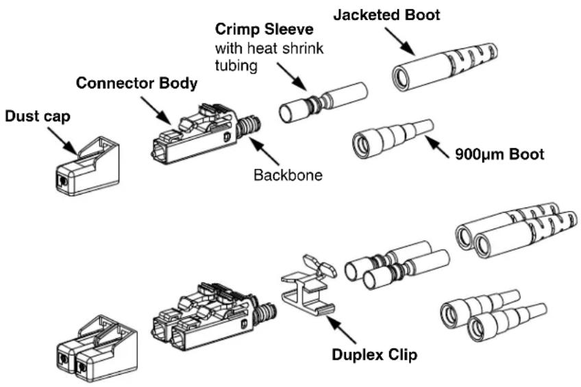
READ ALL INSTRUCTIONS COMPLETELY BEFORE PROCEEDING COMPONENT IDENTIFICATION
CONNECTOR ASSEMBLY


ITEMS REQUIRED FOR TERMINATION
| ITEM PART NUMBER DESCRIPTION | ||
| 1 | CST-115 | Fiber Cable Jacket Stripper |
| 2 FALC | Alcohol Bottle (empty) | |
| 3 | FBFSP | Fiber Buffer Stripper |
| 4 FLPT | LC Crimp Tool | |
| 5 | FSCRIBE | Carbide Scribe |
| 6 | FGLS | Safety Glasses |
| 7 FLCPK | LC Polishing Puck (1.25mm Ferrule) | |
| 8FJPMR | Primer | |
| 9FJPXY | Anaerobic Adhesive | |
| 10 | FHSCT (or) | Heat Shrink Curing Tool (110VAC / 60Hz for 1.6mm/2.0mm installation) |
| FHSCT-W | Heat Shrink Curing Tool (230VAC / 50Hz for 1.6mm/2.0mm installation) | |
| 11 | FKS | Aramid Yarn Shears |
| 12 FPP5-L | 5μm Polishing Film (Alu minum Oxide) | |
| 13 | FPF1-V | 1μm Diamond Polishing Film |
| 14 | FLCPAD | 85 Durometer Polishing Pad |
| 15 FSCDVR | Screwdriver | |
| 16 FSCOPE | 200x Microscope | |
| 17 | FLCASCP | 1.25mm Adapter for FSCOPE |
| 18 | FSTY | Safety Stickers for fiber scraps |
| 19 | FSWB-C | Cleaning Swabs |
| 20 | FSYR-X | Syringes with needle tips |
| 21 FTWZR | Tweezers | |
| 22 FWP-C | Cloth Wipes | |
| 23PFX-0 | Indelible Ink Marking Pen | |
| 24 FLOUPEX10 | Eye Loupe 10X Power | |
| 25 | -- | Isopropyl Alcohol (Reagent Grade, 90% minimum concentration; not available from Panduit) |
| 26 | FLCFPLF-X | .05μm Lapping Film (For singlemode terminations only) |
| 27 | FWBTL | Distilled Water Bottle (empty) |
| -- | -- | Distilled Water (not available from Panduit) |
| OPTIONAL | PN335* | LC Connector Stripping Template |
* denotes stripping template revision letter.
TABLE OF CONTENTS Page(s)
Safety Precautions 2....
900μm Tight-Buffered Fiber Termination 3-6
1.6mm - 2.0mm Jacketed Cable Termination 7-11....
SAFETY PRECAUTIONS
1. SAFETY GLASSES
WARNING: IT IS STRONGLY RECOMMENDED THAT SAFETY GLASSES BE WORN WHEN HANDLING BARE OPTICAL FIBER. THE BARE FIBER IS VERY SHARP AND CAN EASILY DAMAGE THE EYE.
2. ISOPROPYL ALCOHOL
WARNING: ISOPROPYL ALCOHOL IS FLAMMABLE. CONTACT WITH THE ALCOHOL CAN CAUSE IRRITATION TO THE EYES. IN CASE OF CONTACT WITH THE EYES, FLUSH WITH WATER FOR AT LEAST 15 MINUTES. ALWAYS USE ISOPROPYL ALCOHOL WITH PROPER LEVELS OF VENTILATION. IN CASE OF INGESTION, CONSULT A PHYSICIAN IMMEDIATELY.
3. RECOMMENDED ADHESIVE AND PRIMER
WARNING: THE RECOMMENDED ADHESIVE (PANDUIT PART# FJPXY) MAY CONTAIN MALEIC ACID AND METHACRYLIC ESTER. IN CASE OF EYE CONTACT, FLUSH WITH WATER FOR 15 MINUTES AND GET MEDICAL ATTENTION. WASH SKIN AFTER CONTACT. REQUEST M.S.D.S. FOR FURTHER SAFEGUARDS. CHECK "USED BY" DATE ON BOTTLE TO ENSURE BEST PERFORMANCE.
WARNING: THE RECOMMENDED PRIMER (PANDUIT PART# FJPMR) MAY CONTAIN ACETONE. THE PRIMER IS HARMFUL IF INHALED OR SWALLOWED. IN CASE OF CONTACT WITH EYES OR SKIN, FLUSH WITH WATER. GET MEDICAL ATTENTION IN CASE OF INGESTION OR CONTACT WITH EYES. DO NOT INDUCE VOMITING. CHECK "USED BY" DATE ON BOTTLE TO ENSURE BEST PERFORMANCE.
4. DISPOSAL OF BARE FIBERS
WARNING: PICK UP AND DISCARD ALL PIECES OF BARE FIBER WITH STICKY TABS. DO NOT LET CUT PIECES OF FIBER STICK TO CLOTHING OR DROP IN THE WORK AREA WHERE THEY ARE HARD TO SEE AND CAN CAUSE INJURY.
5. LASER LIGHT PROTECTION
WARNING: LASER LIGHT IS INVISIBLE. THE INVISIBLE LIGHT IS POWERFUL ENOUGH TO DAMAGE YOUR EYES. SERIOUS DAMAGE TO THE RETINA OF THE EYE IS POSSIBLE. NEVER LOOK INTO THE END OF A FIBER WHICH MAY HAVE A LASER COUPLED TO IT. SHOULD ACCIDENTAL EYE EXPOSURE TO LASER LIGHT BE SUSPECTED, ARRANGE FOR AN EYE EXAMINATION IMMEDIATELY.
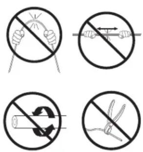
6. CABLE HANDLING
WARNING: FIBER OPTIC CABLE CAN BE DAMAGED BY EXCESSIVE PULLING, TWISTING, CRUSHING OR BENDING STRESSES. CONSULT THE APPROPRIATE SPECIFICATION SHEETS AS PROVIDED BY YOUR CABLE VENDOR. ANY DAMAGE MAY DECREASE OPTICAL PERFORMANCE.


900μm Tight-Buffered Fiber Termination
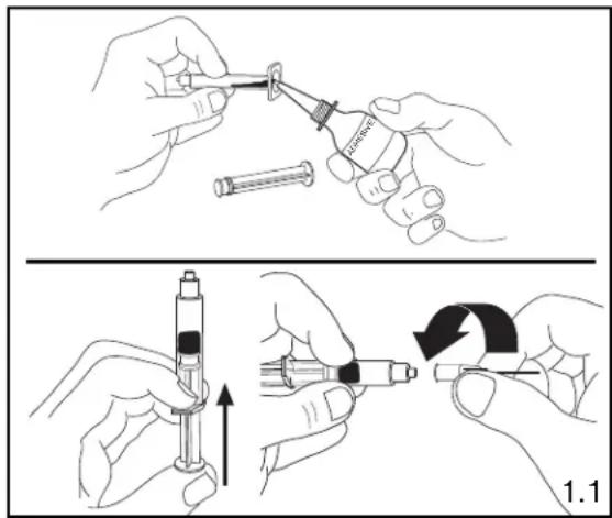
1. PREPARING ADHESIVE AND PRIMER
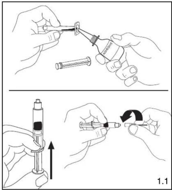
1.1 Remove the plunger from a syringe. Squeeze about 0.5ml of FJPXY Anaerobic Adhesive into the back of the syringe barrel. Insert the plunger. Point opening upward, and squeeze any air out of the barrel. Attach needle to syringe. Adhesive that is stored in a syringe may start to harden within 24 hours.
2. STRIPPING 900μm TIGHT-BUFFERED FIBER
2.1 Insert the fiber end through the small end of the 900 m boot. Slide the boot back out of the way.
2.2 Following the stripping dimensions, use the marking pen to place a mark .53" (13.5mm) from the end of the buffer.
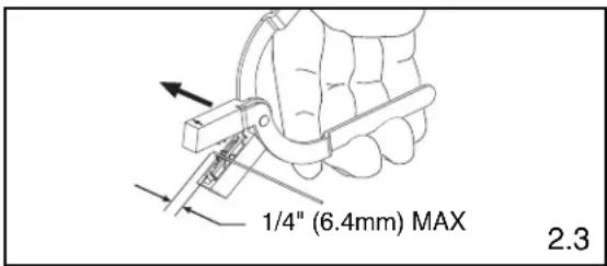
2.3 With the fiber buffer stripper provided, strip the buffer.
BUFFER STRIPPING GUIDELINES:
- Panduit recommends that you remove no more than 1/4" (6.4mm) of buffer at a time to avoid breaking the fiber. Refer to cable manufacturer's buffer stripping guidelines for specific recommendations.
- Hold the buffer stripper such that the arrow on the tool points in the direction of buffer removal.
- Noting the location of the tool's blades, position the fiber in the tool's V-notches. Squeeze the handles firmly, and pull tool in the direction of the arrow on the tool.
- Clean the buffer stripper blades after each strip by holding the handles open, pulling the casings back away from the blades, and letting them snap back against the blades.

natural_image
Diagram of a probe with a pointed tip and arrow indicating direction (no text or symbols)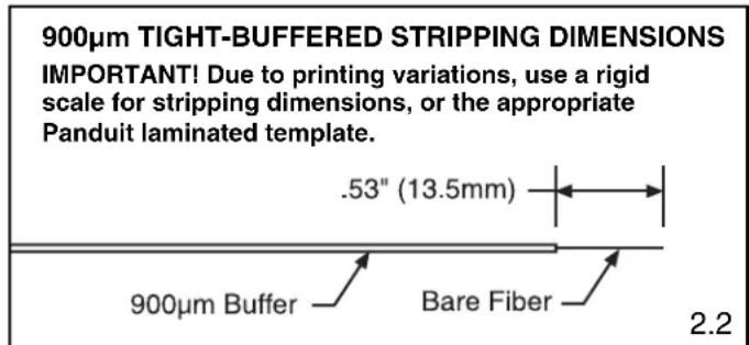
3. ATTACHING FERRULE TO 900μm TIGHT-BUFFERED FIBER
Instructions intended for anaerobic adhesive only.
3.1 Clean the bare fiber using an alcohol (90% minimum concentration) soaked lint-free wipe. The fibers should be free of all coating and residue. Insert fiber without adhesive or primer into ferrule assembly to ensure a proper fit and to remove any debris which may be blocking the ferrule hole. Remove fiber, clean fiber again, and proceed to the next step.

natural_image
Line drawing showing two hands performing a manual manipulation or cleaning procedure, with no visible text or symbols.3.2 Apply primer onto the bare fiber with the brush from the primer bottle, and onto the first 1/8" (3.2 mm) of the buffer next to the exposed fiber. Set fiber aside such that it will not collect debris while completing the next three steps.
3.3 Insert the needle of the adhesive filled syringe into the rear of the connector assembly until the needle bottoms against the rear of the ferrule.
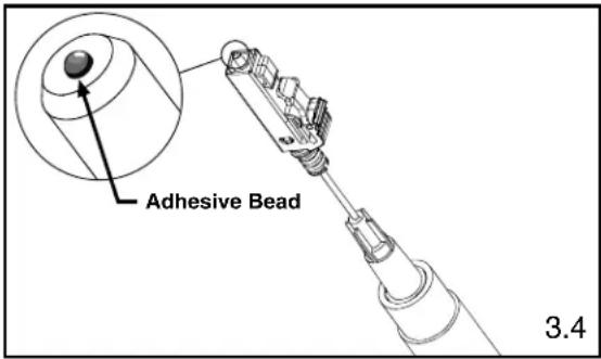
3.4 While pressing the needle firmly against the rear of the ferrule, gently apply pressure on the plunger until a small bead of adhesive forms on the front tip of the ferrule. Wait 3 seconds before removing the needle from the ferrule assembly.
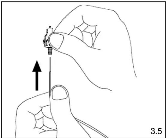
3.5 Carefully but quickly insert the bare fiber through the ferrule in a smooth forward motion. The fiber is fully inserted when the buffer bottoms against the rear of the ferrule. The adhesive will begin to set within seconds.
Note: If adhesive oozes out the back of the assembly, you have injected too much. It is critical to the function of the connector that you wipe away all excess adhesive.
3.6 Allow one minute for the adhesive to harden before cleaving.
3.7 Clean the needle using a dry lint-free wipe. The needle should be free of any excess adhesive before preparing the next connector.
natural_image
Illustration of a hand holding a screwdriver with an upward arrow indicating motion (no text or symbols)4. CLEAVING 900μm TIGHT-BUFFERED FIBER
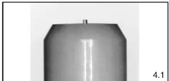
4.1 Using a carbide scribe to cleave, gently make one small score mark across the bare fiber just above the endface of the ferrule. Pull the fiber away from the ferrule and discard it on one of the sticky tabs provided. A short stub of fiber will protrude from the tip of the ferrule when viewed through the FLOUPEX10 Eye Loupe.
4.2 Clean the carbide blade and fingers using a dry lint-free wipe. This will prevent contamination of the connector during polishing and final assembly.
natural_image
Metallic cylindrical object with a small protrusion and label '4.1' (no other text or symbols)

natural_image
Line drawing of a hand holding a curved object with an arrow pointing to it, labeled '4.1' (no text or symbols on the diagram itself)5. POLISHING 900μm TIGHT-BUFFERED FIBER
Carefully read this entire section before proceeding.
POLISHING GUIDELINES
- Keep the puck flat against the polishing film.
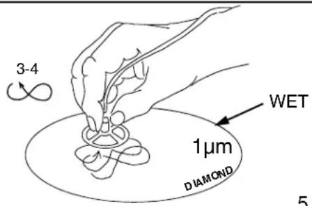
• Figure eights should be about 3" tall and 1.5" wide. - Always polish on a clean area of the 1 m diamond polishing film, with figure eights traversing the film as shown in Figure 5.4.
• One sheet of 5μm (micron) polishing film will polish 2-4 ferrules.
• One sheet of 1μm diamond polishing film will polish 100 ferrules. - One sheet of .05μm lapping film will polish approximately 18-20 ferrules.
- Clean the polishing puck and pad with a clean wipe moistened with alcohol after each step.
• DO NOT OVERPOLISH.
5.1 Hold a piece of 5μm Aluminum Oxide polishing film in the air and gently rub cleaved fiber stub against the film. Using a circular motion, continue rubbing until the end of the fiber is even with the end of the ferrule or adhesive bead. An indication of this is when the stub no longer leaves white traces on the film.
Note: Make sure to hold film so that your fingers are supporting the edges only and are not positioned directly behind fiber.
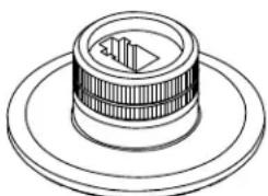
5.2 Thoroughly clean polishing puck and 85 durometer polishing pad using an alcohol soaked wipe. Place a sheet of 1μm diamond polishing film on the pad. Wet film by placing a quarter-sized amount of distilled water in the center of the pad.
5.3 Carefully insert connector into the polishing puck until the connector latches. Insure that the ferrule is protruding from the hole in the underside of the puck. It may be necessary to unlatch and reinsert the connector if the ferrule does not slide through initially.
5.4 Place the puck in the center of the distilled water on the pad. Keeping the puck flat against the film and pad, apply even pressure and polish by making figure eight motions. Continue for 3-4 figure eights.
5.5 Turn the puck over and inspect for any remaining adhesive, indicated by a dark color at the center of the ferrule. Repeat step 5.4 for 1-2 figure eights if adhesive is still present, then reinspect.
5.6 Clean the ferrule tip and puck with an alcohol soaked lint-free wipe. Clean the 1 m diamond polishing film using an alcohol soaked wipe after every 5 connectors.
5.7 Inspect the fiber endface using a microscope. If scratches remain, polish for an additional 1-2 figure eights on the 1 m diamond film and reinspect.
WARNING: NEVER LOOK INTO THE END OF A FIBER WHICH MAY HAVE A LASER COUPLED TO IT.
Note: Each time a mating takes place, clean the ferrule endface thoroughly with an alcohol soaked lint-free wipe.
5.8 For singlemode only: Place a sheet of the .05μm lapping film on the pad. Apply several drops of distilled water onto the center of the film.

natural_image
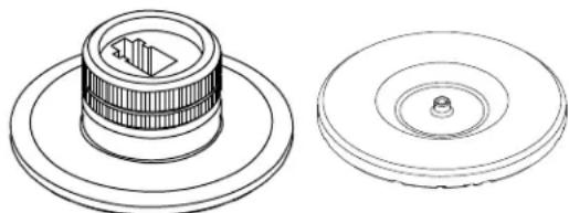
Technical line drawing of a mechanical component with concentric rings and a central slot (no text or symbols)
Design prior to Design after July, July, 2018 2018
Polishing Puck with LC Adapter
5.2
5.4
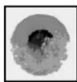
Ferrule Tip After 1μm Diamond Polish
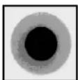
A
B

C
5.5
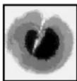
A = Ideal. No blemishes on core or cladding.
B = Good. Cladding is chipped, but core is not.
C = Poor. Scratch across core. Try repolishing or else reterminate.
D = Unacceptable. Fiber has shattered.
Reterminate.
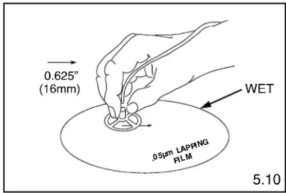
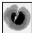
5.9 For singlemode only: Place the puck in the center of the distilled water on the film and pad. Keeping the puck flat against the film and pad, apply even pressure and ONE TIME ONLY drag the puck in a straight line 0.625" (16mm).
CAUTION: Do not exceed 0.625" (16mm) to avoid fiber undercut
5.10 For singlemode only: Wipe the ferrule tip, pad and puck with a dry wipe.
5.11 For singlemode only: Clean the ferrule with a distilled water soaked wipe. Do not use alcohol to clean after using the .05μm lapping film.
5.12 Place a dust cap over the ferrule assembly.
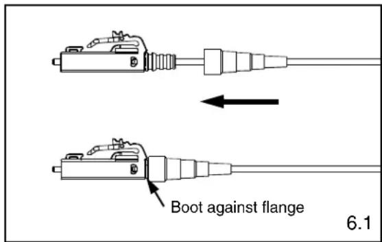
6. ASSEMBLING CONNECTOR AND BOOT
6.1 Push the boot forward onto the grooved area of the backbone until it is against the flange.
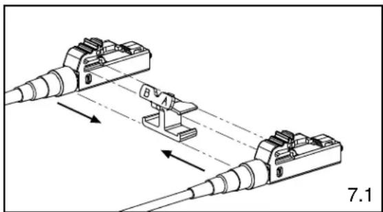
7. ATTACHING DUPLEX CLIP
7.1 With a connector held as shown (latch on top, ferrule facing away), insert the connector into one side of the duplex clip as shown (clip held with the 'A->B' polarity marking upright and facing forward). The upper tab of the clip should slide into the pocket underneath the latch of the connector, and the lower tab should slide under the connector housing and "snap", locking it into place.
7.2 Repeat this procedure for the other connector, completing the duplexing step.
Note: When making cable assemblies, be sure to follow the correct 'A->B' polarity cross-over between connectors.
natural_image
Technical diagram of two electrical connectors with labeled components and directional arrows (no text or symbols)
natural_image
Technical line drawing of a multi-pin electrical connector with labeled terminals A and B, no text or symbols present1.6mm - 2.0mm Jacketed Cable Termination
1. PREPARING ADHESIVE AND PRIMER
1.1 Remove the plunger from a syringe. Squeeze about 0.5ml of FJPXY Anaerobic Adhesive into the back of the syringe barrel. Insert the plunger. Point opening upward, and squeeze any air out of the barrel. Attach needle to syringe. Adhesive that is stored in a syringe may start to harden within 24 hours.
2. STRIPPING 1.6mm - 2.0mm JACKETED CABLE
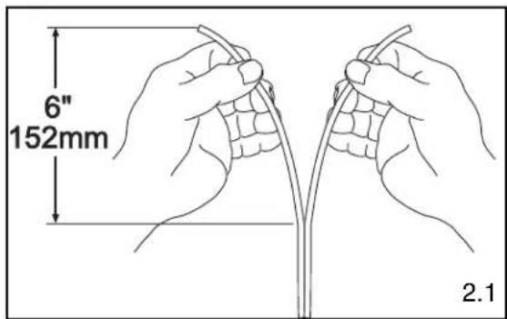
2.1 If using duplex cable, split the two cables approximately 6" (152mm) or as needed.
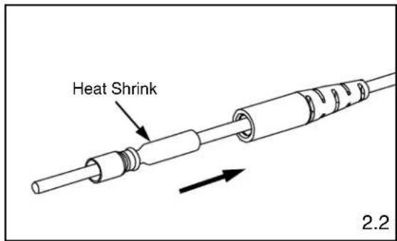
2.2 Insert cable through the small end of the jacketed boot first, then through the heat shrink side of the crimp sleeve. Slide both back out of the way.
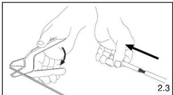
2.3 Following the stripping dimensions, use the marking pen to mark each cable 1.14" (29mm) and 1.46" (37mm) from the end.
2.4 Strip off the cable at the aramid yarn cut mark. To reduce wear on the jacket stripper blades, do not slide the blades along the aramid yarn. Instead, use the tool to cut through the jacket, then pull off the jacket by hand. For 1.6mm - 2.0mm jacketed fiber, use the first hole (marked ".8MM" or #20AWG) from the tip of the jacket stripper.
2.5 Cut aramid yarn flush with the end of the jacket.
2.6 Strip off the cable at the jacket strip mark. Mark the buffer .93" (23.5mm) from the new jacket edge.

natural_image
Illustration of two hands using a tool to apply a curved tool to a piece of material, with no text or symbols present.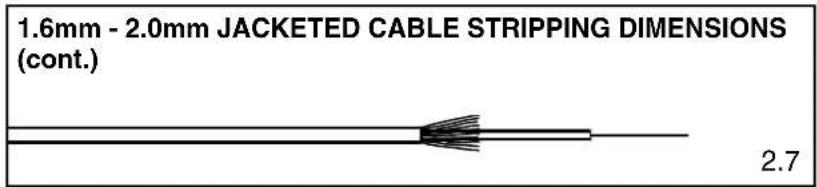
2.7 Using the provided buffer stripper tool, carefully remove the buffer exposing the bare fiber.

BUFFER STRIPPING GUIDELINES:
- Panduit recommends that you remove no more than 1/4" (6.4mm) of buffer at a time to avoid breaking the fiber. Refer to cable manufacturer's buffer stripping guidelines for specific recommendations.
- Hold the buffer stripper such that the arrow on the tool points in the direction of buffer removal.
- Noting the location of the tool's blades, position the fiber in the tool's V-notches. Squeeze the handles firmly, and pull tool in the direction of the arrow on the tool.
- Clean the buffer stripper blades after each strip by holding the handles open, pulling the casings back away from the blades, and letting them snap back against the blades.
3. ATTACHING FERRULE TO 1.6mm - 2.0mm JACKETED CABLE
Instructions intended for anaerobic adhesive only.
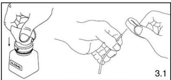
3.1 Clean the bare fiber using an alcohol (90% minimum concentration) soaked lint-free wipe. The fibers should be free of all coating and residue. Insert fiber without adhesive or primer into ferrule assembly to ensure a proper fit and to remove any debris which may be blocking the ferrule hole. Remove fiber, clean fiber again, and proceed to the next step.
3.2 Apply primer onto the bare fiber with the brush from the primer bottle, and onto the first 1/8" (3.2 mm) of the buffer next to the exposed fiber. Set fiber aside such that it will not collect debris while completing the next three steps.
3.3 Insert the needle of the adhesive filled syringe into the rear of the connector assembly until it bottoms against the ferrule.
3.4 While pressing the needle firmly against the rear of the ferrule, gently apply pressure on the plunger until a small bead of adhesive forms on the front tip of the ferrule. Wait 3 seconds before removing the needle from the ferrule assembly.
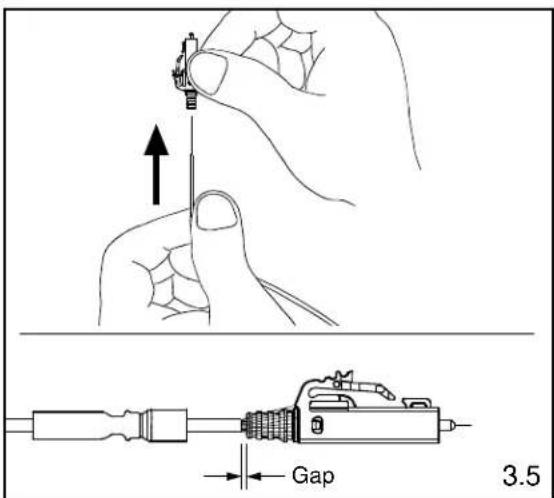
3.5 In a smooth motion, carefully insert fiber into the connector assembly and through the ferrule. The fiber is fully inserted when the buffer bottoms against the ferrule. There will be a slight gap between the cable jacket and the backbone. Do NOT force the jacket up against the backbone. The adhesive will begin to set within seconds.
Note: If adhesive oozes out the back of the assembly, you have injected too much. It is critical to the function of the connector that you wipe away all excess adhesive.
3.6 Allow one minute for the adhesive to harden before cleaving.
3.7 Clean the needle using a dry lint-free wipe. The needle should be free of any excess adhesive before preparing the next connector.
natural_image
Line drawing showing two hands holding a small bottle labeled 'BLOO' and a wire being held, with no text or symbols present.
4. CRIMPING 1.6mm - 2.0mm JACKETED CABLE
Note: Be careful not to break the bare fiber protruding from the ferrule during this step.
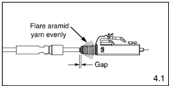
4.1 Flare the aramid yarn evenly around the perimeter of the grooved area of the backbone of the ferrule assembly. Use tweezers for best results. There will be a slight gap between the cable jacket and the backbone.
4.2 Slide the crimp sleeve over the backbone, trapping the aramid yarn between the crimp sleeve and the grooved area of the backbone.
4.3 Align the front edge of the crimp sleeve with the front edge of the crimp die pocket B.
Note: The front edge of the crimp die pocket is the side with the ribs.
4.4 Making sure the crimp sleeve is seated against the backbone, crimp the crimp sleeve.

natural_image
Technical line drawing of a mechanical component with no visible text or symbols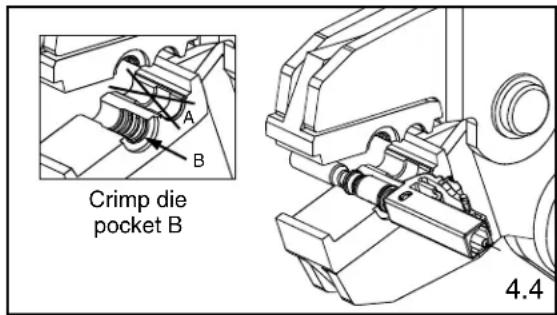
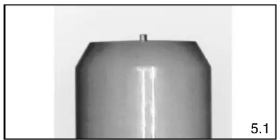
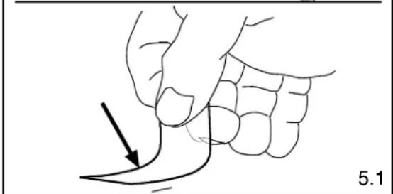
5.1 Using a carbide scribe to cleave, gently make one small score mark across the bare fiber just above the endface of the ferrule. Pull the fiber away from the ferrule and discard it on one of the sticky tabs provided. A short stub of fiber will protrude from the tip of the ferrule when viewed through the FLOUPEX10 Eye Loupe.
5.2 Clean the carbide blade and fingers using a dry lint-free wipe. This will prevent contamination of the connector during polishing and final assembly.
natural_image
Close-up of a metallic cylindrical object with a flat top and a small protrusion, labeled '5.1' in the corner (no other text or symbols)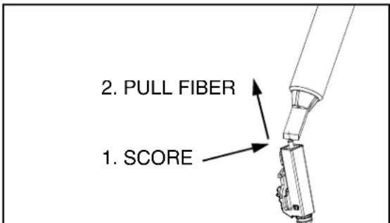
natural_image
Line drawing of a hand holding a curved object with an arrow pointing to it, labeled '5.1' (no text or symbols on the diagram itself)6. POLISHING 1.6mm - 2.0mm JACKETED CABLE
Carefully read this entire section before proceeding.
POLISHING GUIDELINES
- Keep the puck flat against the polishing film.
• Figure eights should be about 3" tall and 1.5" wide. - Always polish on a clean area of the 1 m diamond polishing film, with figure eights traversing the film as shown in Figure 6.4.
• One sheet of 5μm (micron) polishing film will polish 2-4 ferrules.
• One sheet of 1μm diamond polishing film will polish 100 ferrules. - One sheet of .05μm lapping film will polish approximately 18-20 ferrules.
- Clean the polishing puck and pad with a clean wipe moistened with alcohol after each step.
• DO NOT OVERPOLISH.
6.1 Hold a piece of 5μm Aluminum Oxide polishing film in the air and gently rub cleaved fiber stub against the film. Using a circular motion, continue rubbing until the end of the fiber is even with the end of the ferrule or adhesive bead. An indication of this is when the stub no longer leaves white traces on the film. Note: Make sure to hold film so that your fingers are supporting the edges only and are not positioned directly behind fiber.
6.2 Thoroughly clean polishing puck and 85 durometer polishing pad using an alcohol soaked wipe. Place a sheet of 1μm diamond polishing film on the pad. Wet film by placing a quarter-sized amount of distilled water in the center of the pad.
6.3 Carefully insert connector into the polishing puck until the connector latches. Insure that the ferrule is protruding from the hole in the underside of the puck. It may be necessary to unlatch and reinsert the connector if the ferrule does not slide through initially.
6.4 Place the puck in the center of the distilled water on the pad. Keeping the puck flat against the film and pad, apply even pressure and polish by making figure eight motions. Continue for 3-4 figure eights.
6.5 Turn the puck over and inspect for any remaining adhesive, indicated by a dark color at the center of the ferrule. Repeat step 6.4 for 1-2 figure eights if adhesive is still present, then reinspect.
6.6 Clean the ferrule tip and puck with an alcohol soaked lint-free wipe. Clean the 1 m diamond polishing film using an alcohol soaked wipe after every 5 connectors.
6.7 Inspect the fiber endface using a microscope. If scratches remain, polish for an additional 1-2 figure eights on the 1 m diamond film and reinspect.
WARNING: NEVER LOOK INTO THE END OF A FIBER WHICH MAY HAVE A LASER COUPLED TO IT.
Note: Each time a mating takes place, clean the ferrule endface thoroughly with an alcohol soaked lint-free wipe.
6.8 For singlemode only: Place a sheet of the .05μm lapping film on the pad. Apply several drops of distilled water onto the center of the film.

natural_image
Technical line drawing of a mechanical component with two views: top shows a cylindrical component with internal features, bottom shows a circular housing with a central hole (no text or symbols)Design prior to Design after July, July, 2018 2018
Polishing Puck with LC Adapter
6.2

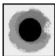
Ferrule Tip After 1μm Diamond Polish

A

B
C
6.5
A = Ideal. No blemishes on core or cladding.
B = Good. Cladding is chipped, but core is not.
C = Poor. Scratch across core. Try repolishing or else reterminate.
D = Unacceptable. Fiber has shattered.
Reterminate.
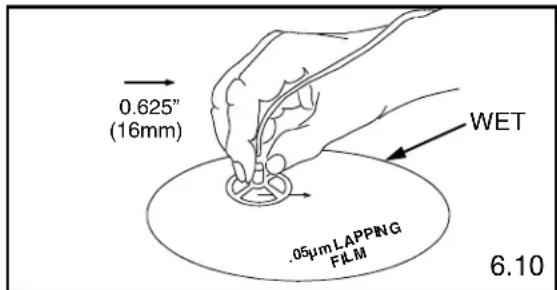
6.9 For singlemode only: Place the puck in the center of the distilled water on the film and pad. Keeping the puck flat against the film and pad, apply even pressure and ONE TIME ONLY drag the puck in a straight line 0.625" (16mm).
CAUTION: Do not exceed 0.625" (16mm) to avoid fiber undercut
6.10 For singlemode only: Wipe the ferrule tip, pad and puck with a dry wipe.
6.11 For singlemode only: Clean the ferrule with a distilled water soaked wipe. Do not use alcohol to clean after using the .05μm lapping film.
6.12 Place a dust cap over the ferrule assembly.
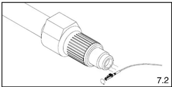
7. CURING HEAT SHRINK TUBING
7.1 Turn the heat adjustment knob so the white line is centered in the notch.
7.2 Turn heat shrink curing tool "on". (The temperature of the hot air stream at the nozzle should be 220^ F - 240^ F)
7.3 Hold onto the connector.
7.4 Bring the heat shrink tubing into the hot air stream. Hold the heat shrink tubing about 1/2" away from the nozzle. Rotate the connector for 20-30 seconds so that the heat shrink tubing is completely cured onto the jacket.
7.5 Remove the connector from the hot air stream.
7.6 Turn heat shrink curing tool "off".
8. ASSEMBLING CONNECTOR AND BOOT
8.1 Slide the boot over the crimp sleeve and onto the backbone. Push the boot over the flange towards the shoulder. The boot should snap in place onto the flange.
9. ATTACHING DUPLEX CLIP
9.1 With a connector held as shown (latch on top, ferrule facing away), insert the connector into one side of the duplex clip as shown (clip held with the 'A->B' polarity marking upright and facing forward). The upper tab of the clip should slide into the pocket underneath the latch of the connector, and the lower tab should slide under the connector housing and "snap", locking it into place.
9.2 Repeat this procedure for the other connector, completing the duplexing step.
Note: When making cable assemblies, be sure to follow the correct ‘A->B’ polarity cross-over between connectors.
For Instructions in Local Languages
and Technical Support:
www.panduit.com/resources/install_maintain.asp

www.panduit.com
natural_image
Technical illustration of a mechanical component with a wire and connector, labeled 7.2 (no text or symbols on the diagram itself)
natural_image
Line drawing of a USB connector with a cable, no text or symbols present

natural_image
Diagram of two connected electrical connectors with directional arrows indicating connection points (no text or symbols)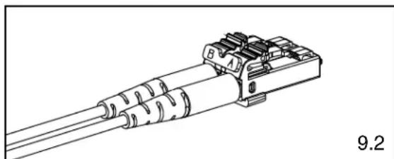
natural_image
Technical line drawing of a mechanical connector with threaded ends and mounting bracket (no text or symbols)E-mail:


- READ ALL INSTRUCTIONS COMPLETELY BEFORE PROCEEDING COMPONENT IDENTIFICATION
- TABLE OF CONTENTS Page(s)
- SAFETY PRECAUTIONS
- SAFETY GLASSES
- ISOPROPYL ALCOHOL
- RECOMMENDED ADHESIVE AND PRIMER
- DISPOSAL OF BARE FIBERS
- LASER LIGHT PROTECTION
- CABLE HANDLING
- 900μm Tight-Buffered Fiber Termination
- PREPARING ADHESIVE AND PRIMER
- STRIPPING 900μm TIGHT-BUFFERED FIBER
- BUFFER STRIPPING GUIDELINES:
- ATTACHING FERRULE TO 900μm TIGHT-BUFFERED FIBER
- CLEAVING 900μm TIGHT-BUFFERED FIBER
- POLISHING 900μm TIGHT-BUFFERED FIBER
- POLISHING GUIDELINES
- Ferrule Tip After 1μm Diamond Polish
- ASSEMBLING CONNECTOR AND BOOT
- ATTACHING DUPLEX CLIP
- 1.6mm - 2.0mm Jacketed Cable Termination
- STRIPPING 1.6mm - 2.0mm JACKETED CABLE
- ATTACHING FERRULE TO 1.6mm - 2.0mm JACKETED CABLE
- CRIMPING 1.6mm - 2.0mm JACKETED CABLE
- POLISHING 1.6mm - 2.0mm JACKETED CABLE
- WARNING: NEVER LOOK INTO THE END OF A FIBER WHICH MAY HAVE A LASER COUPLED TO IT.
- CURING HEAT SHRINK TUBING
- ASSEMBLING CONNECTOR AND BOOT
- ATTACHING DUPLEX CLIP
Brand : Panduit
Model : FSCRIBE
Category : Network accessory