ATW-1701P1 - Wireless Microphone Audio-Technica - Free user manual and instructions
Find the device manual for free ATW-1701P1 Audio-Technica in PDF.


| Product Type | Digital Wireless Microphone System (Camera-Mount) |
| Model Number | ATW-1701P1 |
| Brand | Audio-Technica |
| Receiver Model | ATW-R1700 |
| Transmitter Models | ATW-T1001 (UniPak body-pack) or ATW-T1002 (handheld) |
| Operating Frequency | 2.4 GHz ISM band (2400-2483.5 MHz) |
| Diversity System | Frequency, Time, and Space Diversity |
| Audio Sampling | 24-bit / 48 kHz |
| Dynamic Range | >109 dB (A-weighted) |
| Total Harmonic Distortion | <0.05% typical |
| Operating Range | 30 m (100 ft) radius, 60 m (200 ft) diameter typical (open environment) |
| Max Simultaneous Channels | 8 (without frequency coordination) |
| Receiver Dimensions | 27.8 mm D x 56.0 mm W x 91.4 mm H (1.09" x 2.20" x 3.60") |
| Receiver Weight | 105 g (3.7 oz) |
| Receiver Battery | 3.7V Li-ion rechargeable, 5.5 Wh, 1460 mAh |
| Receiver Battery Life | 12 hours (depending on conditions) |
| Receiver Charging Time | 4 hours 30 minutes |
| Transmitter Battery | 2 x AA alkaline (not included) |
| Transmitter Battery Life | >7 hours (alkaline) |
| Transmitter RF Power | 10 mW |
| Audio Output | 3.5 mm TRS balanced or unbalanced (dual mono) |
| Headphone Output | 3.5 mm mono/stereo, 70 mW + 70 mW (32Ω) |
| Included Accessories | AC adapter, USB cable, 3.5 mm stereo cable, camera shoe mount |
| Cleaning | Clean with a dry cloth only; do not use liquids |
| Safety | Do not expose to rain or moisture; no user-serviceable parts inside |
Frequently Asked Questions - ATW-1701P1 Audio-Technica
User questions about ATW-1701P1 Audio-Technica
0 question about this device. Answer the ones you know or ask your own.
Ask a new question about this device
Download the instructions for your Wireless Microphone in PDF format for free! Find your manual ATW-1701P1 - Audio-Technica and take your electronic device back in hand. On this page are published all the documents necessary for the use of your device. ATW-1701P1 by Audio-Technica.
USER MANUAL ATW-1701P1 Audio-Technica
System 10 Portable Camera-Mount Wireless
Digital Wireless System
Installation and Operation
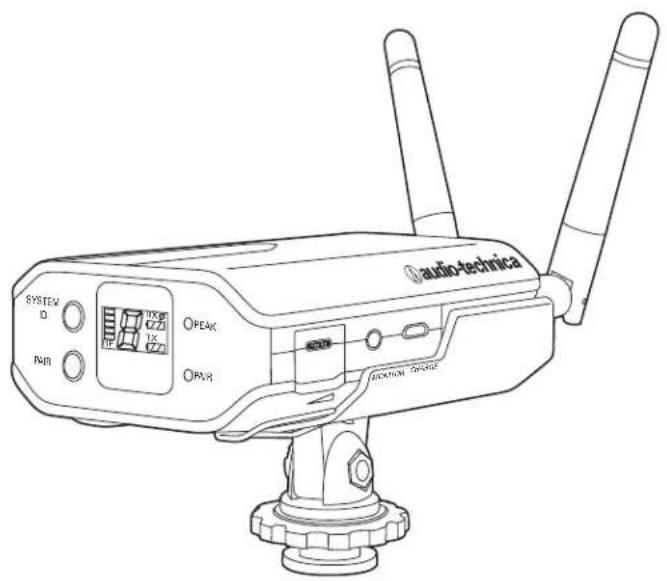
ATW-1701
UniPak® Transmitter System
ATW-1702
Handheld Microphone System
System 10 Portable Camera-Mount Wireless Installation and Operation

RISK OF ELECTRIC SHOCK

WARNING: TO REDUCE THE RISK OF FIRE OR ELECTRIC SHOCK, DO NOT REMOVE SCREWS. NO USER-SERVICEABLE PARTS INSIDE. REFER SERVICING TO QUALIFIED SERVICE PERSONNEL.
WARNING: TO REDUCE THE RISK OF FIRE OR ELECTRIC SHOCK, DO NOT EXPOSE THE APPLIANCE TO RAIN OR MOISTURE.
CERTIFICATION: THIS DEVICE COMPLIES WITH PART 15 OF THE FCC RULES. THIS DEVICE COMPLIES WITH INDUSTRY CANADA LICENSE-EXEMPT RSS STANDARDISI. OPERATION IS SUBJECT TO THE FOLLOWING TWO CONDITIONS: (1) THIS DEVICE MAY NOT CAUSE HARMFUL INTERFERENCE, AND (2) THIS DEVICE MUST ACCEPT ANY INTERFERENCE RECEIVED, INCLUDING INTERFERENCE THAT MAY CAUSE UNDESired OPERATION.
WARNING: Changes or modifications not expressly approved in writing by Audio-Technica may void the user's authority to operate this equipment.
RF Exposure Statement: This transmitter must not be co-located or operated in conjunction with any other antenna or transmitter.
The ATW-R1 700 complies with FCC/C radiation exposure limits set forth for an uncontrolled environment and meets the FCC radio frequency (RF) Exposure Guidelines and RSS-102 of the IC radio frequency (RF) Exposure rules. This equipment has very low levels of RF energy that it deemed to comply without maximum permissive exposure evaluation. (MPE). But it is desirable that it should be installed and operated keeping the radiator at least 20cm or more away from person's body.
The available scientific evidence does not show that any health problems are associated with using low power wireless devices. There is no proof, however, that these low power wireless devices are absolutely safe. Low power Wireless devices emit low levels of radio frequency energy (RFI in the microwave range while being used. Whereas high levels of RF can produce health effects (by heating tissue), exposure of low-level RF that does not produce heating effects cause no known adverse health effects. Many studies of low-level RF exposures have not found any biological effects. Some studies have suggested that some biological effects might occur but such findings have not been confirmed by additional research. ATW-T1001, ATW-T1002 has been tested and found to comply with FCC/IC radiation exposure limits set fourth for an uncontrolled environment and meets the FCC radio frequency (RFI) Exposure Guidelines and RSS-102 of the IC radio frequency (RFI) Exposure rules.
Note: This equipment has been tested and found to comply with the limits for a Class B digital device, pursuant to part 15 of the FCC Rules. These limits are designed to provide reasonable protection against harmful interference in a residential installation. This equipment generates, uses and can radiate radio frequency energy and, if not installed and used in accordance with the instructions, may cause harmful interference to radio communications. However, there is no guarantee that interference will not occur in a particular installation. If this equipment does cause harmful interference to radio or television reception, which can be determined by turning the equipment off and on, the user is encouraged to try to correct the interference by one or more of the following measures:
- Reorient or relocate the receiving antenna.
- Increase the separation between the equipment and receiver.
- Connect the equipment into an outlet on a circuit different from that to which the receiver is connected.
- Consult the dealer or an experienced radio/TV technician for help.
CAUTION! Electrical shock can result from removal of the receiver cover. Refer servicing to qualified service personnel. No user/serviceable parts inside. Do not expose to rain or moisture. The circuits inside the receiver and transmitter have been precisely adjusted for optimum performance and compliance with federal regulations. Do not attempt to open the receiver or transmitter. To do so will void the warranty, and may cause improper operation.
Danger of explosion if battery is replaced incorrectly. If battery dies, send receiver to Audio-Technica or other qualified service center so battery can be replaced with same or equivalent type. Likewise, send damaged, inoperable receivers to Audio-Technica or other qualified service center for recycling—do not throw away receiver as its battery contains toxic materials.
Notice to individuals with implanted cardiac pacemakers or AICD devices: Any source of RF (radio frequency) energy may interfere with normal functioning of the implanted device. All
wireless microphones have low-power transmitters (less than 0.05 watts output) which are unlikely to cause difficulty, especially if they are at least a few inches away. However, since a "body-pack" mic transmitter typically is placed against the body, we suggest attaching it at the belt, rather than in a shirt pocket where it may be immediately adjacent to the medical device. Note also that any medical-device disruption will cease when the RF transmitting source is turned off. Please contact your physician or medical-device provider if you have any questions, or experience any problems with the use of this or any other RF equipment.
Important Safety Instructions
-
Read these instructions.
-
Keep these instructions.
-
Heed all warnings.
-
Follow all instructions
-
Do not use this apparatus near water.
-
Clean only with a dry cloth.
-
Install in accordance with the manufacturer's instructions.
-
Do not install near any heat sources such as radiators, heat registers, stoves, or other apparatus (including amplifiers) that produce heat.
-
Unplug this apparatus during lightning storms or when unused for long periods of time.
-
Refer all servicing to qualified service personnel. Servicing is required when the apparatus has been damaged in any way, such as power-supply cord or plug is damaged, liquid has been spilled or objects have fallen into the apparatus, the apparatus has been exposed to rain or moisture, does not operate normally, or has been dropped.
CAUTION on handling receiver battery
- Battery packs may explode or release toxic materials. Risk of fire or burns. Do not open, crush, modify, disassemble, heat above 140°F (60°C) or incinerate.
- Battery must be replaced and recycled by qualified service personnel. Do not attempt to replace battery on your own.
- If the battery leaks and the liquid contacts your skin or clothing, immediately flush with clean water.
- If the battery leaks and the liquid contacts your eyes, immediately wash thoroughly with clean water and seek medical assistance.
• Do no short circuit; may cause burns or catch fire. - Charge battery only with the supplied AC adapter and USB cable.
Thank you for choosing an Audio-Technica professional wireless system. You have joined thousands of other satisfied customers who have chosen our products because of their quality, performance and reliability. This wireless microphone system is the successful result of years of design and manufacturing experience.
Audio-Technica's System 10 Portable Camera-Mount is a digital wireless system designed to provide rock-solid performance along with easy setup and clear, natural sound quality. Featuring a compact design, System 10 Portable Camera-Mount is available in handheld, lavalier and body-pack configurations. Operating in the 2.4 GHz range, far from TV and DTV interference, System 10 Portable Camera-Mount offers extremely easy operation and instantaneous channel selection. Up to eight channels may be used together without any frequency coordination problems or group selection issues.
System 10 wireless ensures clear communications by providing three levels of diversity assurance: frequency, time, and space. Frequency Diversity sends the signal on two dynamically allocated frequencies for interference-free communication. Time Diversity sends the signal in multiple time slots to maximize immunity to multipath interference. Finally, Space Diversity uses two antennas on each transmitter and receiver to maximize signal integrity.
Each System 10 professional digital wireless system includes a receiver and camera shoe mount, and either a body-pack transmitter or a handheld microphone/transmitter.
Because System 10 packaging is designed to hold all versions of the system, some compartments in the carton may be intentionally left empty.
The ATW-R1700 receiver includes a switching power supply that automatically adapts to changes in mains voltage.
The versatile ATW-T1001 UniPal® body-pack transmitter has both a high-impedance input for instruments, and a low-impedance input with bias connection for use with dynamic and electret condenser microphones. The ATW-T1002 handheld transmitter features a unidirectional dynamic microphone element.
Both the body-pack and handheld transmitters use internal AA batteries and have Power/Mute switches and input Trim (level) adjustments.
Receiver Installation
Location
For best operation the receiver should be at least 3' (1 m) above the ground and at least 3' (1 m) away from a wall or metal surface to minimize reflections. Keep the receiver antennas away from noise sources such as other digital wireless equipment, microwave ovens, as well as away from large metal objects. Keep System 10 receiver 30' (9 m) away from wireless access points. In multi-channel systems, position receivers at least 3' (1 m) apart and keep operating transmitters at least 6' (2 m) from the receivers to help assure maximum RF performance.
Output Connection
The ATW-R1700 has a single audio output jack that accepts the 3.5 mm ( ^1/_8 ) cable included in the package.
Use the Audio Output Selector Switch to choose between a balanced and an unbalanced dual mono signal.
The 3.5 mm (1/8") Headphone Monitor output works with mono or stereo headphones (the output sends a dual mono audio signal to stereo headphones). Use the Headphone Level Control to adjust the volume.
Power Connection
NOTE: Use only the supplied AC adapter and power cord to power or charge receiver. To use AC power, connect the power cord's USB A-type male port to the AC adapter and connect the Micro-USB B port to the USB Power Input on the side of the receiver. Next, plug the adapter into a standard 120 Volt 60 Hz or 230 volt 50 Hz (depending on global location) AC power outlet. The AC adapter and USB cable also charges the receiver's internal battery. Charge battery in an environment with moderate temperature (41°F - 95°F). The system will not charge in temperatures below 32°F or above 104°F in order to prevent potential damage to battery. For safety and to conserve energy, unplug the AC adapter from the AC outlet when the system is not in use. Store receiver in a cool place.
Antennas
For best reception, position the removable antennas in the shape of a "V" so that both tilt 45°.
ATW-R1700 Receiver Controls and Functions
Figure A — Front Panel Controls and Functions
- Removable Antennas: Position the antennas as shown.
- Power/Battery Indicator: Glows green when receiver is on and battery is charged. Flashes green when battery needs to be charged. Glows red when battery is charging.
- Power Switch: Press and hold to turn receiver on or off.
Figure B — Rear Panel Controls and Functions
- System ID Select Switch: Press to cycle through System ID numbers. (System ID is the identical number assigned to a paired receiver and transmitter.)
- Pairing Switch: Press to initiate pairing
- LCD System Display contains:
a. RF Signal Level Indicator: shows strength of the RF signal received from the transmitter
b. The System ID Display: shows the System ID number
c. The Receiver Battery Gauge RX: shows the capacity of the receiver's internal battery/charging status
d. The Transmitter Battery Gauge TX: shows the capacity of the transmitter's batteries
- AF Peak Indicator: Only lights when audio distortion is present at maximum modulation. Attenuator does not affect the indicator.
- Pairing Indicator: Flashes green in pair mode. Glows green when transmitter is paired.
Figure C — Right Side Controls and Functions
- Headphone Level Control: This control is used to adjust the volume of the signal sent to the headphones. Roll control to the right to increase the volume.
- Headphone Monitor: Accepts 3.5 mm ( 18 ) connector. Plug in either a mono or stereo headphone to monitor receiver signal.
- Power Input: Connect the AC Power Supply adapter included in the system to charge/operate the receiver.
Figure D— Left Side Controls and Functions
- Audio Output Selector Switch: Move right for balanced output or left for unbalanced (dual mono) output.
- Audio Output Attenuator Switch: Default is 0 dB. Move one stop left to reduce the audio output by 10 dB or two stops left to reduce output by 20 dB.
- Audio Output Jack: TRS balanced or unbalanced (dual mono)
3.5 mm ( ^1/_8 ) jack. Can be connected to the input of a camera or mixer.
Figure E— Camera Shoe Mount
Camera Shoe Mount allows receiver to be attached to a camera or tripod. Slide mount onto receiver from the rear so mount engages the grooves on the sides of the receiver and slips under the clip on the bottom. Slide until rear of mount is flush with rear of receiver. The mount bracket
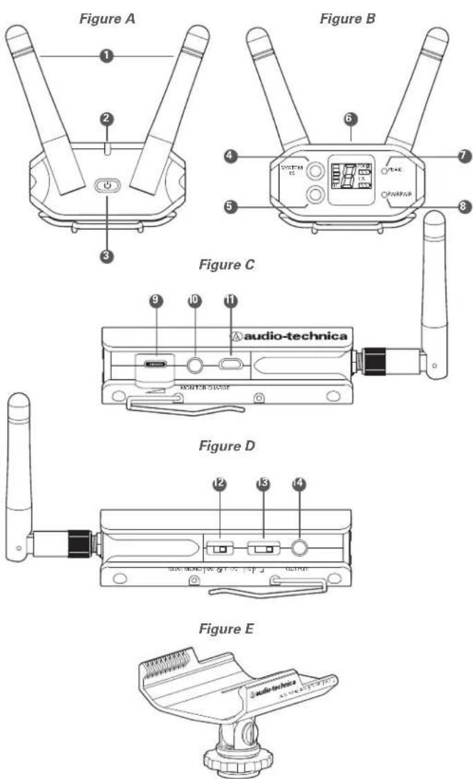
connects to the hot shoe of most DSLR cameras: slide into shoe and tighten nut to secure. The bracket's 14 " socket also allows it to be attached to a tripod, shoulder rig or other device with a 14 " screw.
ATW-T1002 Transmitter Setup Controls and Functions
Battery Selection and Installation
Two alkaline AA batteries are recommended. When inserting the battery, observe correct polarity as marked inside the battery compartment.
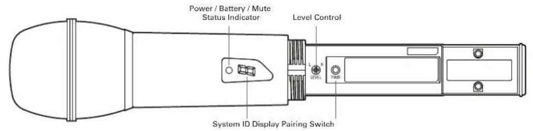
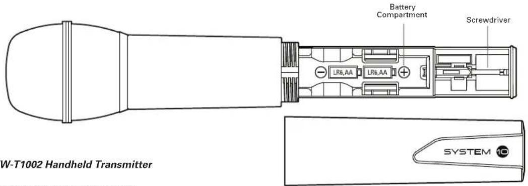
Figure F — ATW-T1002 Handheld Transmitter
Handheld Transmitter Battery Installation
- While holding the upper part of the transmitter body just below the ball-screen, unscrew the lower body cover and slide it off to expose the battery compartment (Fig. F).
- Carefully insert two fresh AA alkaline batteries, observing polarity markings.
- Screw the body back together. Do not overtighten.
Handheld Transmitter Battery Condition Indicator
After the batteries are installed, press and hold the Power/Mute switch on the bottom of the handheld transmitter until the indicator LED turns green. If the indicator LED does not light up when the Power/Mute switch is pressed, the batteries are installed incorrectly or they are dead. The indicator LED will flash to show low-battery condition.
Handheld Transmitter Mute Function
With the transmitter on, a slight touch of the power switch will toggle between muted and unmuted operation. Red indicator LED shows muted operation. Green indicator LED shows unmuted operation.
Handheld Transmitter Mute Lock Function
Transmitter must be off to activate mute lock. Press and hold the Pairing Switch and then press and hold the Power/Mute button until transmitter powers on. Note: There is no dot next to the System ID when mute lock is activated.
Transmitter must be off to deactivate mute lock. Press and hold the Pairing Switch and then press and hold the Power/Mute button until transmitter powers on. When deactivated, a dot will display next to the System ID.

natural_image
Abstract geometric symbol with concentric circles and a triangle inside (no text or labels)Power/Mute Switch
Handheld Transmitter Pairing Switch
Used to complete pairing sequence. See page 6.
Handheld Transmitter Level Control
Used to set microphone level. See page 6.
Handheld Transmitter Screwdriver
Used to adjust Level Control. See page 6.
Handheld Transmitter System ID Display
Shows System ID. See page 6. Note: System ID is an identical number assigned to a paired receiver and transmitter for identification purposes. When Power is applied, the System ID Display on the transmitter glows bright and then turns off to conserve battery life. To turn the System ID Display back on, mute and unmute the transmitter.
System 10 Portable Camera-Mount Wireless Installation and Operation
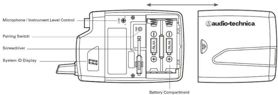
Figure G - ATW-T1001 UniPak Transmitter
UniPak ^® Transmitter Battery Installation
- Slide off the battery cover.
- Carefully insert two fresh AA alkaline batteries, observing polarity markings.
- Replace the battery cover (Fig. G).
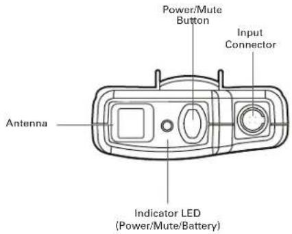
UniPak ^® Transmitter Power/Mute/Battery Indicator
After the battery is installed, press and hold the Power/Mute button until the indicator LED turns green (Fig. H). If the indicator LED does not light up when the power button is pressed, the batteries are installed incorrectly or they are dead. The indicator LED will flash to show low-battery condition.
UniPak ^® Transmitter Mute Function
With the transmitter on, a slight touch of the Power/Mute button will toggle between muted and unmuted operation. Red indicator LED shows muted operation. Green indicator LED shows unmuted operation.
UniPak ^® Transmitter Mute Lock Function
Transmitter must be off to activate mute lock. Press and hold the Pairing Switch and then press and hold the Power/Mute button until transmitter powers on. Note: There is no dot next to the System ID when mute lock is activated.
Transmitter must be off to deactivate mute lock. Press and hold the Pairing Switch and then press and hold the Power/Mute button until transmitter powers on. When deactivated, a dot will display next to the System ID.
UniPak ^® Transmitter Input Connection
Connect an audio input device (microphone or guitar cable) to the audio input connector on the top of the transmitter. A number of Audio-Technica professional microphones and cables are available separately, pre-terminated with a UniPak® input connector (see www.audio-technica.com).
UniPak ^® Transmitter Antenna
The UniPak ^® transmitter includes a permanently-attached antenna. If the received signal is marginal, experiment with different transmitter positions on your body or instrument; or try repositioning the receiver. Do not attempt to remove, replace or change the length of the transmitting antenna.
UniPak ^® Transmitter Pairing Switch
Used to complete pairing sequence. See page 6.
UniPak® Transmitter Microphone/Instrument Level Control
Used to set microphone/instrument level. See page 6.
Figure H — UniPak ^® Transmitter
UniPak® Transmitter Screwdriver
Used to adjust Level Control. See page 6.
UniPak ^® Transmitter System ID Display
Shows System ID. See page 6. Note: System ID is an identical number assigned to a paired receiver and transmitter for identification purposes. When power is applied, the System ID Display on the transmitter glows bright and then turns off to conserve battery life. To turn the System ID Display back on, mute and unmute the transmitter.
System Operation
Turn down the headphone volume control and the camera/mixer level before starting up the wireless system. Do not switch on the transmitter yet.
Receiver on...
Press and hold receiver power button to turn receiver on. Power/Battery indicator will glow green and the blue System ID number on the front panel will illuminate.
If the Power/Battery indicator flashes green, the receiver's battery needs to be charged. You can charge the battery with the supplied AC adapter and USB cable, following the instructions under Power Connection on page 3. The LCD RX Battery Gauge will blink during charging and a lightning bolt symbol will appear to the right of "RX." The Power/Battery indicator will glow red while the battery is charging and turn green when charging is complete. Audio-Technica recommends fully charging the internal battery before using the receiver for the first time. Average charge time takes 4 hours 30 minutes. To help maintain the battery, it is best to operate the receiver (at least occasionally) without the AC power supply and recharge when needed. Also, avoid storing a fully charged receiver for a long period of time.
Transmitter on...
When the transmitter is switched on, the receiver's green pair indicator will light, and two indicators light on the transmitter: the transmitter Power / Battery / Mute status indicator will glow green; and the transmitter blue System ID display will illuminate. The blue System ID display on the transmitter and receiver turns off after 30 seconds to conserve battery power; the transmitter Power / Battery / Mute status indicator will remain illuminated, indicating transmitter status.
To re-illuminate System ID display, press the Power / Mute switch.
Note: this will alter the transmitter mute status. A slight touch of the power switch toggles between muted and unmuted operation.
The transmitter's Power / Battery / Mute status indicator glows red when transmitter is muted, or green to indicate unmuted status. In a low-battery situation, the Power / Battery / Mute status indicator begins to blink.
The transmitters have a soft-touch power switch. When the switch is set to "Mute" (red indicator LED), the transmitter produces RF with no audio signal. When the switch is "On" (green indicator LED) the transmitter produces both RF and audio. Excessive audio input to the transmitter will cause the receiver's red AF Peak indicator to light.
Receiver Attenuator
Typically, the receiver Audio Output Attenuator switch should be set at 0dB, and the overall gain should be adjusted from the camera. If a camera lacks that capability or if sensitivity is too high, use the Audio Output Attenuator switch to reduce the gain until the signal does not distort.
Input Level Adjustment
Input trimmer controls in the transmitters enable you to maximize performance for a particular microphone or guitar sensitivity, or to adjust for different acoustic input levels.
Adjusting Input Level — UniPak ^® Transmitter
Slide the battery cover off the transmitter and remove the screwdriver from its clip. Using the screwdriver, gently turn the "VOL" (Volume – Microphone/Instrument Level) all the way up (clockwise, toward "H"). Check for excessive gain by speaking / singing into the microphone at typically loud levels while watching the receiver's
Peak Indicator. If the Peak indicator does light, turn the "VOL" control slightly counterclockwise until the Peak indicator no longer lights with maximum audio input to the transmitter.
Adjusting Input Level — Handheld Transmitter
Unscrew the lower body cover and slide it off, exposing the screwdriver and "LEVEL" (Gain Trimmer) control (Fig. C). Remove the screwdriver from its clip. Gently turn the "LEVEL" control to its full clockwise position (toward the side marked "H"), the factory setting. Check for excessive gain by speaking/singing into the microphone at typically loud levels while watching the receiver's AF Peak indicator. If the AF Peak indicator does light, turn the "LEVEL" control slightly counterclockwise until the AF Peak indicator no longer lights with maximum audio input to the mic/transmitter.
Return the screwdriver to its clip and close and secure the lower body. No further transmitter gain adjustments should be needed, as long as the acoustic input does not change significantly.
CAUTION! The small trimmer controls are delicate; use only the supplied screwdriver. Do not force the trimmers beyond their normal 190^ range of rotation.
Return the screwdriver to its storage clip when not in use.
Setting System ID Number & Pairing your Transmitter and Receiver
Your system has been preconfigured at the factory to operate with no other pairing setup required; it will work out of the box. That is, your receiver and transmitter are already a digital pair, and they have been assigned the same System ID number.
The pairing instructions outlined below will help you if you find it necessary to change system ID numbers in multiple-system configurations, or pair a new transmitter to an existing receiver.
NOTE: System ID is an identical number assigned to a paired receiver and transmitter for identification purposes. The System ID number is not related to transmitting frequency. Due to the dynamic nature of System 10 automatic frequency selection, the actual transmitting frequencies may change during power-up or performance. These frequency changes are seamless and imperceptible to the ear.
Pairing Receiver with Transmitters
Note: Up to eight transmitters may be paired with the receiver.
-
Turn the receiver and first transmitter on.
-
Press the System ID button on the receiver to choose an ID number from 1 to 8. The receiver's display will show your new ID and begin to blink.
-
Within 15 seconds, press and hold the Pair button on the receiver for about one second. The Pair light will begin to blink green. The receiver is now in Pair Mode.
Note: If the receiver Pair button is not pressed within 15 seconds, the system ID number will revert to its previous setting.
-
Open the transmitter and press and hold its Pair button within 30 seconds of entering Pair Mode. The transmitter display will now show the System ID number you have chosen on the receiver. The receiver's Pair light will glow steady, indicating you have successfully paired your system.
-
To pair an additional transmitter, you must switch off first transmitter by pressing and holding its Power/Mute button. Turn the second transmitter on and follow instructions 2-4 above, making sure to assign a different System ID number to the new transmitter.
-
Repeat for each additional transmitter. Remember to switch off all transmitters already paired before adding a new one and to use a unique ID number for each transmitter.
Note: With all transmitters turned off, the receiver's System ID Display will cycle through all currently paired ID numbers. Turn on a transmitter to activate its pairing with the receiver. The receiver recognizes only one transmitter at a time. That transmitter must be turned off before the receiver will recognize another paired transmitter. *If that transmitter is turned off out of range, the receiver will not recognize another paired transmitter until the receiver is reset by disconnecting the power supply.
Clearing Individual ID Pairings
- Press the receiver's System ID button to select the ID number you wish to clear. The number will begin to blink.
- Press and hold the Pair and then ID button for about three seconds, until the display shows a blinking "o." This indicates that your selected ID number has been cleared.
- Release the Pair and ID buttons and, after a few seconds, the display will stop blinking and return to normal operation.
- Repeat to clear additional ID pairings.
Clearing All ID Pairings
- Press and hold the receiver's Pair and then ID button for about three seconds, until the display shows a blinking "o."
- Release the Pair and ID buttons. Then, within three seconds, press and hold the Pair and ID buttons again, until the display shows a blinking "A." This indicates that all your paired ID numbers have been cleared.
- After blinking three seconds, the "A" will change to "-" to indicate that there are no paired transmitters.
Ten Tips to Obtain the Best Results
- Use only fresh alkaline or fully charged replaceable batteries for the transmitter.
-
Position the receiver so that it has the fewest possible obstructions between it and the normal location of the transmitter. Line-of-sight is best.
-
The transmitter and the receiver should be as close together as conveniently possible, but not less than 6' (2 m).
- While System 10 has been designed to conveniently mount on cameras, please keep other wireless devices (including wireless systems and routers) away from System 10 receivers. For best performance, some routers and Wi-Fi-based wireless systems may need to be up to 30 feet away from System 10 receivers.
- The receiver antennas should be kept away from any metal.
- Use the transmitter level control to optimize performance for your sound source.
- If the receiver output is set too low, the overall signal-to-noise ratio of the system may be reduced. Conversely, if the Attenuator of the receiver is set too high, it may over-drive the input of the camera/mixer, causing distortion. Adjust the output level of the receiver so the highest sound pressure level going into the camera/mixer causes no input overload, and yet permits the camera/mixer level controls to operate in their "normal" range (not set too high or too low). This provides the optimum signal-to-noise for the entire system.
- Turn the transmitter off when not in use. Remove the battery if the transmitter is not to be used for a period of time.
- Unplug the receiver from the AC outlet when the system is not in use.
System Operating Frequencies
Automatic Frequency Selection
System 10 wireless systems operate in automatically selected frequencies in the 2.4 GHz range, far from TV and DTV interference. Up to eight channels may be used together without any frequency coordination problems or group selection issues. Every time a receiver/transmitter pair is powered on, it automatically selects clear frequencies. Due to the dynamic nature of System 10 automatic frequency selection, these transmitting frequencies may change during power-up or performance if interference is encountered. These frequency changes occur at both the receiver and transmitter; they are seamless and imperceptible to the ear.
System Frequencies
For future reference, please record your system information here (the serial number appear on each transmitter, and on the bottom of each receiver):
Receiver
Model ATW-R1700 Serial Number
Transmitter
Model ATW-T100 Serial Number 1 or 2
Specifications
OVERALL SYSTEM
| Operating Frequencies 2.4 GHz ISM band (2400 to 2483.5 MHz) | |
| Dynamic Range >109 dB (A-weighted), typical | |
| Total Harmonic Distortion <0.05% typical | |
| Operating Range 30 m (100') radius, 60 m (200') diameter typical | |
| Open range environment with no interfering signals | |
| Operating Temperature Range very low temperatures | 0°C to +40°C (32°F to 104°F)Battery performance may be reduced at |
| Frequency Response | 20 Hz to 20 kHzDepending on microphone type |
| Audio Sampling | 24 bit / 48 kHz |
RECEIVER
| Receiving System | Diversity (frequency/time/space) |
| Maximum Output Level mono, unbalanced: 0 dBV | 3.5 mm ( ^1/_8 ), TRS balanced: +6 dBV Dual |
| Monitor Output Level | 3.5 mm ( ^1/_8 ); 70 mW +70 mW (32Ω) |
| Power Supply switched mode USB-type external power supply | 100-240V AC (50/60 Hz) to 5V DC 0.5A |
| Internal Battery | 3.7V rechargeable Li-ion battery |
| Battery Rating | 5.5 Wh1,460 mAh |
| Battery Life | 12 hoursDepending on environmental conditions |
| Battery Charging Time 4 hours 30 minutesDepending on environmental conditions | |
| Charging Temperature Range | 5°C to +35°C (41°F to 95°F) |
| Dimensions27.8 mm (1.09") D | 56.0 mm (2.20") W x 91.4 mm (3.60") H x |
| Net Weight | 105 grams (3.7 oz) |
| Accessories Included adapter (USB-type); USB cable; AT83493.5 mm ( ^1/_8 ) stereo cable | |
UNIPAK® TRANSMITTER
| RF Output Power | 10 mW |
| Spurious Emissions | Following federal and national regulations |
| Input Connection | Four-pin Locking ConnectorPin 1: GND, Pin 2: INST INPUT,Pin 3: MIC INPUT, Pin 4: DC BIAS +9V |
| Batteries (not included) | Two 1.5V AA |
| Battery Life | >7 hours (alkaline) |
| Depending on battery type and use pattern | |
| Dimensions | 70.2 mm (2.76") W x 107.0 mm (4.21") H x |
| 24.9 mm (0.98") D | |
| Net Weight (without batteries) | 100 grams (3.5 oz) |
HANDHELD TRANSMITTER
| RF Output Power | 10 mW |
| Spurious Emissions | Following federal and national regulations |
| Element | Dynamic |
| Polar Pattern | Hypercardioid |
| Batteries (not included) | Two 1.5V AA |
| Battery Life | >7 hours (alkaline) |
| Depending on battery type and use pattern | |
| Dimensions | 254.8 mm (10.03") long. |
| 50.0 mm (1.97") diameter | |
| Net Weight (without batteries) | 280 grams (9.9 oz) |
| Accessory Included | AT8456a Quiet-Flex ^TM stand clamp |
* In the interest of standards development, A.T.U.S. offers full details on its test methods to other industry professionals on request.
To reduce the environmental impact of a multi-language printed document, product information is available online at www.audio-technica.com in a selection of languages.
- System 10 Portable Camera-Mount Wireless
- System 10 Portable Camera-Mount Wireless Installation and Operation
- RISK OF ELECTRIC SHOCK
- Important Safety Instructions
- CAUTION on handling receiver battery
- Receiver Installation
- Location
- Output Connection
- Power Connection
- Antennas
- ATW-R1700 Receiver Controls and Functions
- Figure A — Front Panel Controls and Functions
- Figure B — Rear Panel Controls and Functions
- Figure C — Right Side Controls and Functions
- Figure D— Left Side Controls and Functions
- Figure E— Camera Shoe Mount
- ATW-T1002 Transmitter Setup Controls and Functions
- Battery Selection and Installation
- Handheld Transmitter Battery Installation
- Handheld Transmitter Battery Condition Indicator
- Handheld Transmitter Mute Function
- Handheld Transmitter Mute Lock Function
- Handheld Transmitter Pairing Switch
- Handheld Transmitter Level Control
- Handheld Transmitter Screwdriver
- Handheld Transmitter System ID Display
- UniPak ® Transmitter Battery Installation
- UniPak ® Transmitter Power/Mute/Battery Indicator
- UniPak ® Transmitter Mute Function
- UniPak ® Transmitter Mute Lock Function
- UniPak ® Transmitter Input Connection
- UniPak ® Transmitter Antenna
- UniPak ® Transmitter Pairing Switch
- UniPak® Transmitter Microphone/Instrument Level Control
- UniPak® Transmitter Screwdriver
- UniPak ® Transmitter System ID Display
- System Operation
- Receiver on...
- Transmitter on...
- Receiver Attenuator
- Input Level Adjustment
- Adjusting Input Level — UniPak ® Transmitter
- Adjusting Input Level — Handheld Transmitter
- Setting System ID Number & Pairing your Transmitter and Receiver
- Pairing Receiver with Transmitters
- Clearing Individual ID Pairings
- Clearing All ID Pairings
- Ten Tips to Obtain the Best Results
- System Operating Frequencies
- Automatic Frequency Selection
- System Frequencies
- Receiver
- Transmitter
- Specifications
Brand : Audio-Technica
Model : ATW-1701P1
Category : Wireless Microphone